My own board (50mm x 30mm)
-
@gloob To burn a boatloader with Arduino IDE, you will need a second Arduino or working atmega328 onto which you can load a sketch.
I have an older Arduino board (the one I bought when I first started exploring this new hobby), and I use the setup as described in this article: http://www.gammon.com.au/bootloader@GertSanders said:
@alexsh1 I completely switched off the BoD in my fuse settings, this saves the battery even more. I found that the processor kept working down to around 1,64V. Even my NRF24 worked to that low level, because the last message I received in my Domoticz from that node gave a battery voltage of 1.64V
Anyway, since I monitor all battery levels via a script in Domoticz, there is no need for BoD.Yes, I noticed that you have atmega328pO4M8i.bootloader.extended_fuses=0x07 which is as you said switches off all BoD levels.
Thanks for an interesting info regarding the voltage. This is a very good news. I guess you are getting a notification in Domoticz if a battery level goes down to 1.64V?
I'am going to setup a programmer on mega 2560 tonight, but meantime ordered one of the programming shields to streamline the process - http://www.boardstuff.co.uk/
-
@alexsh1 I actually set up a notification on each Voltage sensor within Domoticz, so that I get a prowl message when the voltage drops below 2V. This then gives me some time to replace the batteries. The 1.64V was when I intentionally let a sensornode die out, just to see what would happen. I never let the voltage drop that low now. All my nodes now have batteries that should last at least 9-12 months (depends on the sensor and it's activities).
-
@GertSanders
Thanks for your help. I was now able to burn the bootloader and will start testing the board tomorrow when I have a valid 3,3V source to power the radio.
Can I power the radio from an FTDI programmer if the programmer is set to 3,3V power? If yes, how to set the two jumpers? -
@gloob if you power via a 3V3 FTDI interface, then you only need to close jumper 1 to connect the Vcc corcuit with the 3V3 circuit.
-
@GertSanders
Thanks for your support. I have now the serial gateway sketch running and output of the arduino seems good:0;0;3;0;9;gateway started, id=0, parent=0, distance=0 0;0;3;0;14;Gateway startup complete.I will now order some Si7021 sensors and continue my testing.
Can I use the following sensors:
Si7021 Industrial High Precision Humidity Sensor I2C Interface for Arduino
-
@gloob I'm using the same sensors for Temperature and Humidity. The pinout of these boards is what I based my pinout on my red board on. (3V3, GND, SCL, SDA). I'm using now 5 of these.
-
Ok, after a few long days I managed to burn the bootloader. For those who are struggling with the same problem please note the following:
- Use Nick Gammon's website and optiboot bootloader (512kb only). I had a standard ATmegaBOOT_168_atmega328_pro_8MHz_hex (Lilypad 8 MHz loader) and could not make it work with 3.3.v.
- Important: the 2048kb bootloader's (Lilypad 8MHz) address is 0x7800. For the optiboot (512Kb) you need to change it for 0x7E00. Now everything works fine - I just need now to change fuses to make sure the voltage can go down below 2V.
@GertSanders I wonder what sketches do you use with this board? it is nice to have Si7021 (it is pin-for-pin for your board) for temp and humidity.
-
@alexsh1 I make my own sketches, the one for my board with SI7021 is used most in my house. I also have a repeater, a GSM node, a sleeper node which wakes up when switches are tripped (basis for upcoming door sensor node). I work with the development version of the library (1.6.0-beta) of Mysensors
I added my Temp/Hum sketch as inspiration: TEMPNODESI7021.ino
-
Interesting
@GertSanders GSM node? is it a standalone or you have it hooked up to this node?
I have a GSM node connected to a couple of SSRs to control water heating - sadly this is not connected to MySensors -
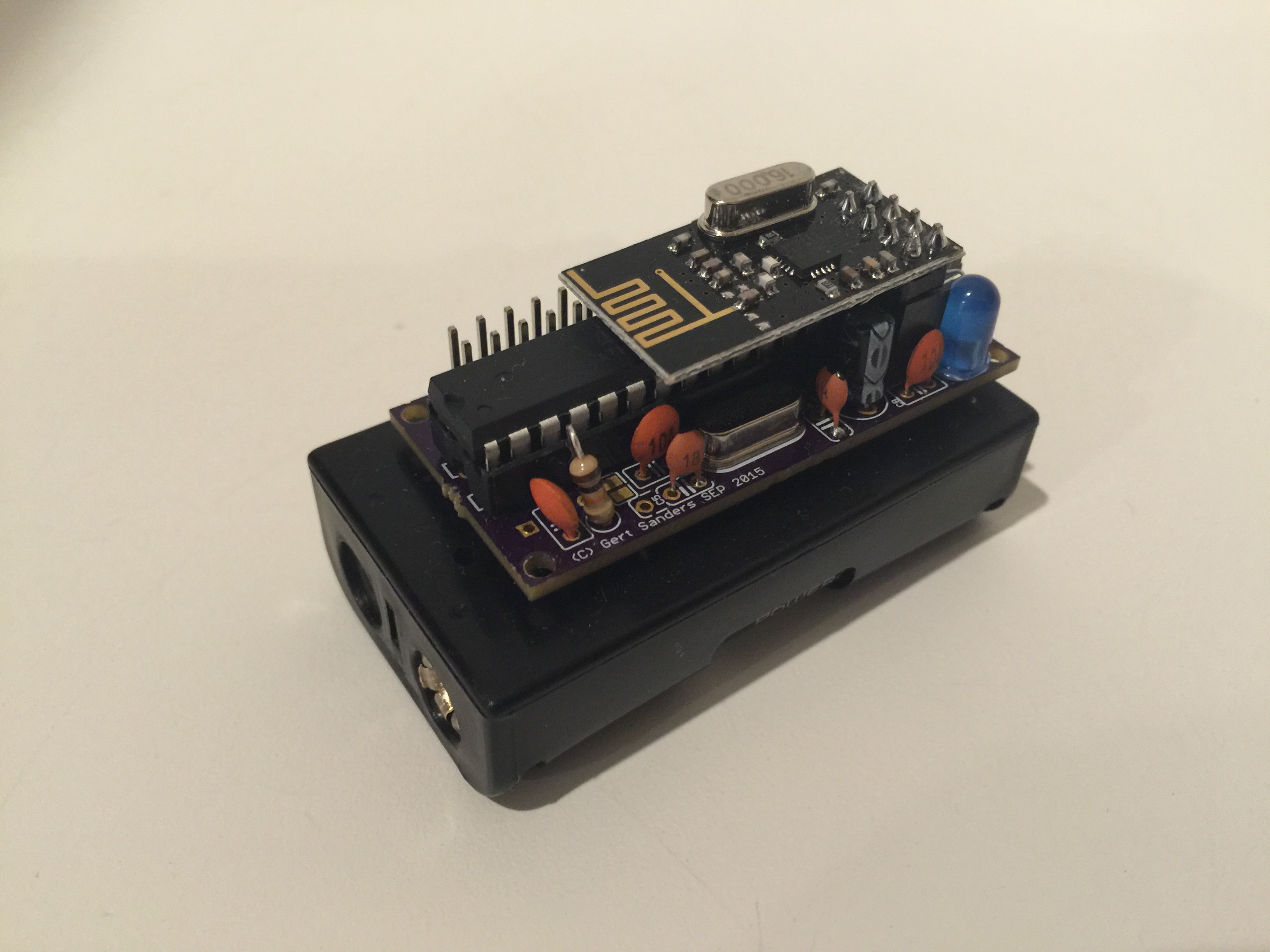
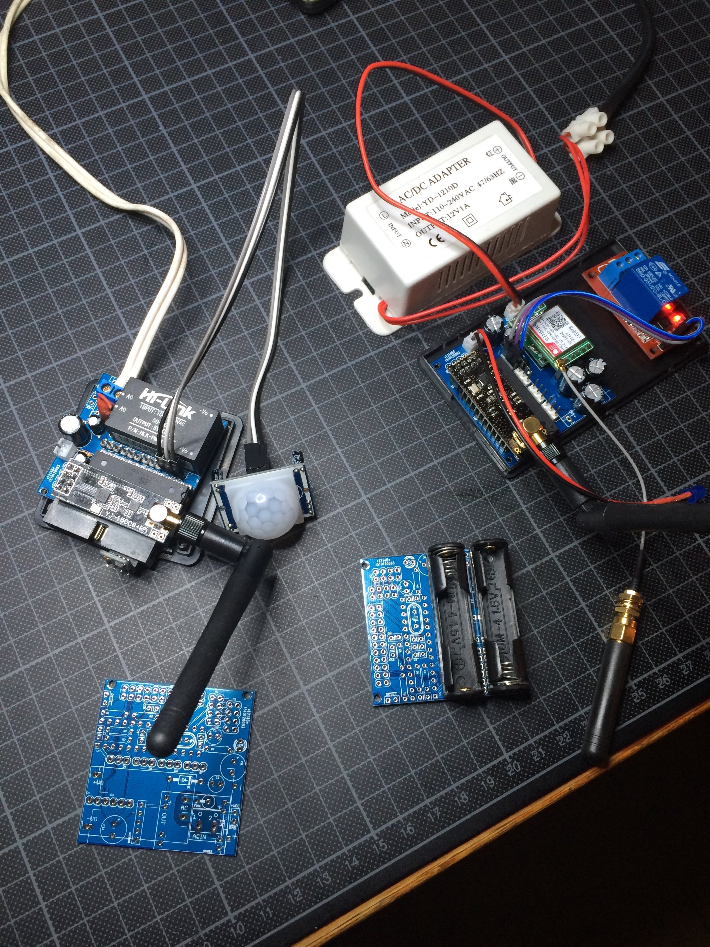
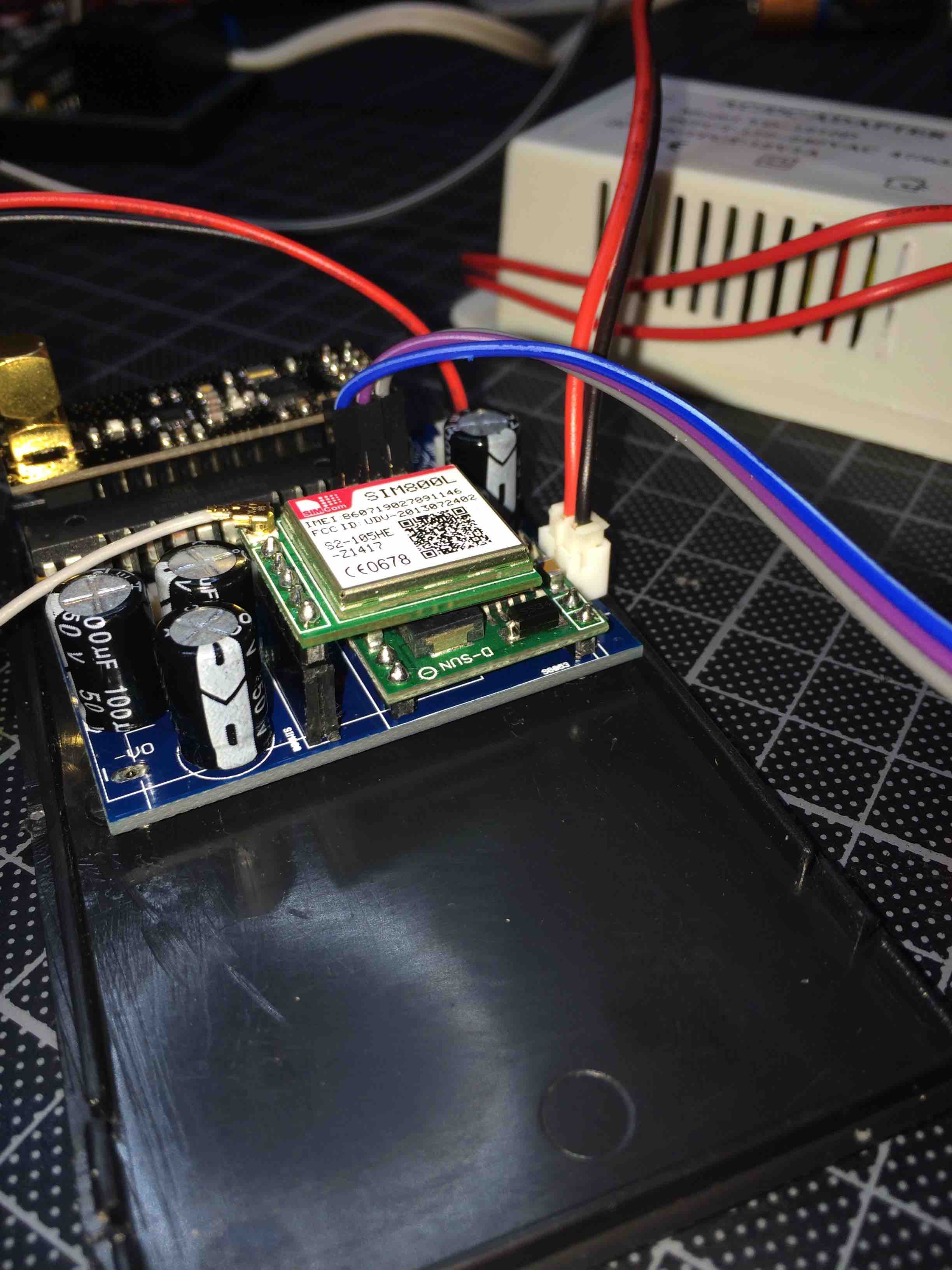
@alexsh1 It is based on my AC capable board, is a normal atmega328p board, but with a SIM800L mounted on it. This module allows me to send and receive SMS's, and I use one of the digital output pins to control a waterpump. I have a second AC based board ready which will be my MySensors SMS gateway. This means it will be able to receive V_TEXT and send that to the default GSM number as a SMS. It should be possible to receive SMS and send that as V_TEXT to other nodes, but so far I have not started the design of the second sketch yet.
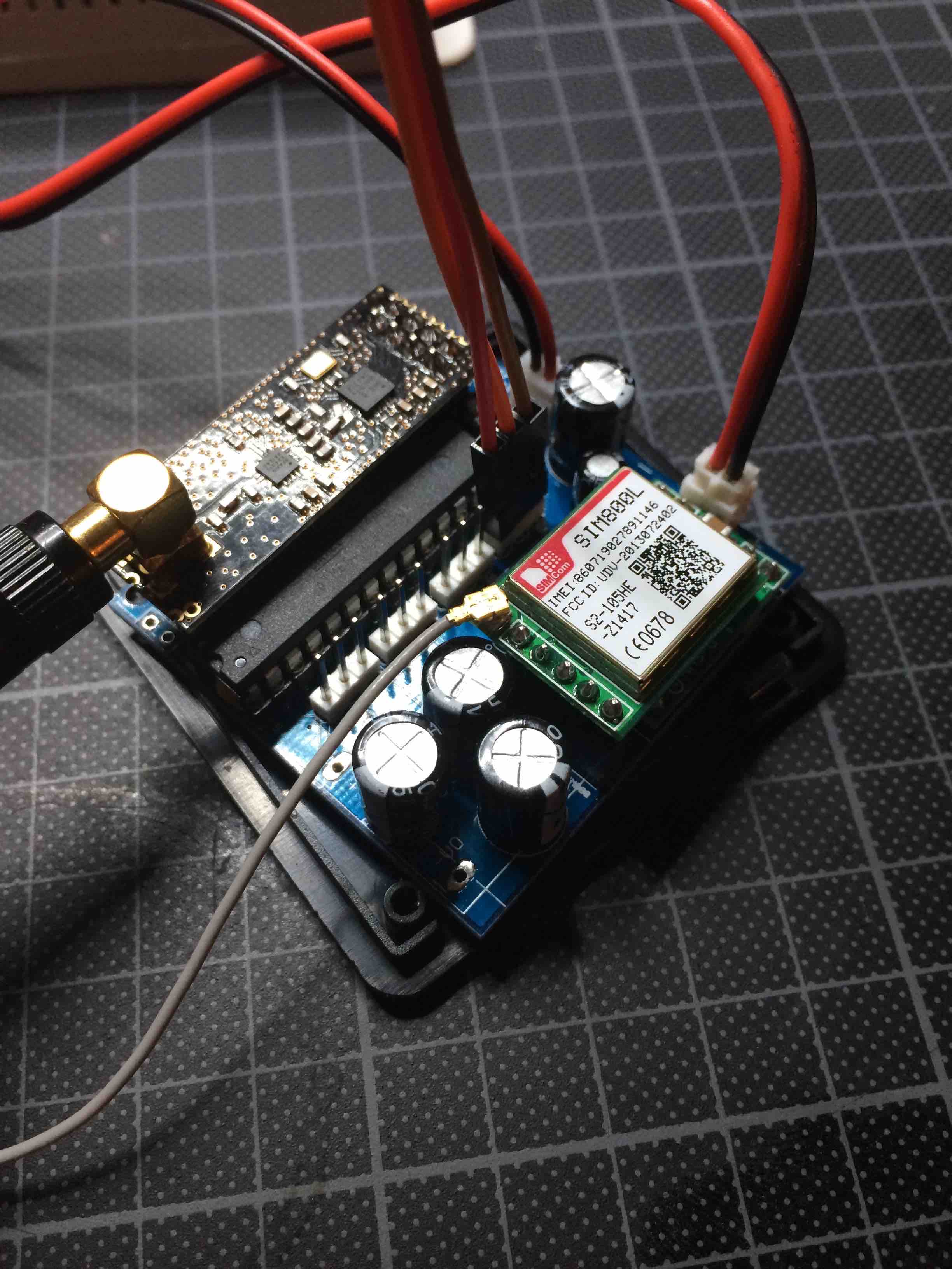
You see it here also (top right) with the relay module and the white AC-DC converter connected.
Side view:
-
@alexsh1 It is based on my AC capable board, is a normal atmega328p board, but with a SIM800L mounted on it. This module allows me to send and receive SMS's, and I use one of the digital output pins to control a waterpump. I have a second AC based board ready which will be my MySensors SMS gateway. This means it will be able to receive V_TEXT and send that to the default GSM number as a SMS. It should be possible to receive SMS and send that as V_TEXT to other nodes, but so far I have not started the design of the second sketch yet.
You see it here also (top right) with the relay module and the white AC-DC converter connected.
Side view:
@GertSanders said:
@alexsh1 It is based on my AC capable board, is a normal atmega328p board, but with a SIM800L mounted on it. This module allows me to send and receive SMS's, and I use one of the digital output pins to control a waterpump. I have a second AC based board ready which will be my MySensors SMS gateway. This means it will be able to receive V_TEXT and send that to the default GSM number as a SMS. It should be possible to receive SMS and send that as V_TEXT to other nodes, but so far I have not started the design of the second sketch yet.
I only have 1-2 high current (3kWh at 240V resistive load) devices at home and I am already controlling them as well my internet router (remote reboot if no internet) via SMS. At this stage I need a larger property to expand my home automation lol :satisfied: :satisfied: :satisfied:
-
@GertSanders
Do you have a source or shop for the AAA battery holder with solder pins? I did only find some for AA batteries.@gloob said:
@GertSanders
Do you have a source or shop for the AAA battery holder with solder pins? I did only find some for AA batteries.Would you mind me asking why you'd need AAA batteries? Much less capacity and the holder is not much smaller. I have been using Eneloop AA rechargable lithium batteries (http://www.ebay.co.uk/itm/4pcs-1-5V-AA-2200mWh-Lithium-li-ion-Rechargeble-Battery-4-PORTS-AA-charger-/272027421169?hash=item3f561909f1:g:r9AAAOSwMTZWSFHz) and they are holding up really well. The advantage is that they hold 1.5V almost until they are discharged unlike NiMh
-
@gloob I got my AAA holders from Aliexpress.
-
-
Indeed, those :+1:
-
@gloob Not yet, some of mine have been running for 2months with a voltage drop of less then 1%