What radio to use? NRF24L01+, RFM69, RFM73 ?
-
@fets said:
s so you need to adapt level
I just got my rfm69hw´s and connected it to an arduino nano for a couple of seconds before i realized that I needed to adapt the level. Is it possible that it survived this mistake?
I have nov connected a IIC I2C Interface Level Conversion Module 5-3v
I connected NSS,Mosi,SCK and GND to the "B" side and connected the arduino nano to the "A" side. Is this correct? -
@Cliff-Karlsson seems correct.
Personnaly I use 3 * 2 resistors (10k and 4.7k) for NS, MOSI and SCK rfm69hw inputs.
Don't forget to change MyTransportRF69 contructor to use high power RFM69 ;) -
@fets said:
H version stands for High power.
C version is pin compatible with RFM12.
RFM69 uses SPI so the connections are :Arduino RFM69
10 <-------------------> NSS
11 <-------------------> MOSI
12 <-------------------> MISO
13 <-------------------> SCK
DI00 <-------------------> 2
GND <-------------------> GND
3.3V
ANA : antennaNSS, MOSI and SCK are inputs so you need to adapt level if you use 5V arduino
I have connected a RFM69HW to my arduino nano+rpi gateway and have connected a RFM69W+Mini Pro 3.3V to a soil sensor but nothing shows up in Domoticz. Do I have to do anything else? Do I need a external antenna? The two RFM's is only like 1m apart.
-
Do I need to alter the code for the gateway or the sensor-sketches?
-
@fets said:
H version stands for High power.
C version is pin compatible with RFM12.
RFM69 uses SPI so the connections are :Arduino RFM69
10 <-------------------> NSS
11 <-------------------> MOSI
12 <-------------------> MISO
13 <-------------------> SCK
DI00 <-------------------> 2
GND <-------------------> GND
3.3V
ANA : antennaNSS, MOSI and SCK are inputs so you need to adapt level if you use 5V arduino
I have connected a RFM69HW to my arduino nano+rpi gateway and have connected a RFM69W+Mini Pro 3.3V to a soil sensor but nothing shows up in Domoticz. Do I have to do anything else? Do I need a external antenna? The two RFM's is only like 1m apart.
@Cliff-Karlsson said:
Do I need a external antenna? The two RFM's is only like 1m apart.I never tested without antenna. I used simple wire the length dependinf of your frequency?
Did you look at your arduino serial outpout ?
If there is nothing, it may that because RFM69 init failed -
Yes you should put an antenna on. It doesn't have a PCB trace antenna. A simple piece of wire, typically cut to 1/4 wavelength, will work fine.
-
Ok, I have some thin insulated copper wire, will that work? And how long wire will I need for the 868mhz frequency?
But just to be clear, do I need to alter the gateway or the sensor sketches in some way to have it use the rfm radio?
-
Thanks, sorry for repeating the question but do I need to alter the code on gateway or sensors?
-
You only need to create a MyTransportRFM69 instead of MyTransportNRF24. This is the constructor : MyTransportRFM69 (RFM69_FREQUENCY, RFM69_NETWORKID, RF69_SPI_CS, RF69_IRQ_PIN, isRFM69HW, RF69_IRQ_NUM);
if you use a RFM99H, you have to set the 5th parameter (isRFMHW) to true. -
Sorry for being semi-retarded, but is this done in the gateway sketch? Sensor
-sketch or both? Is there any documentation on this part as I am a complete beginner. -
both, here is the documentation
-
@Cliff-Karlsson You have to change the following setting in Myconfig.h for you radio
/**********************************
*  RFM69 Driver Defaults
***********************************/
// Default network id. Use the same for all nodes that will talk to each other
#define RFM69_NETWORKID     100

// Default frequency to use. This must match the hardware version of the RFM69 radio (uncomment one):
 #define RFM69_FREQUENCY   RF69_433MHZ
//#define RFM69_FREQUENCY   RF69_868MHZ
//#define FREQUENCY     RF69_915MHZ

// Enable this for encryption of packets
//#define RFM69_ENABLE_ENCRYPTION
#define RFM69_ENCRYPTKEY  "sampleEncryptKey"
Then in MySensor.h you change the following:
ifndef MySensor_h #define MySensor_h #include "Version.h" // Auto generated by bot #include "MyConfig.h" #include "MyHw.h" #include "MyTransport.h" //#include "MyTransportNRF24.h" #include "MyTransportRFM69.h" #include "MyParser.h" #ifdef MY_SIGNING_FEATURE #include "MySigning.h" #include "MySigningNone.h" #endif #include "MyMessage.h" #ifdef MY_OTA_FIRMWARE_FEATURE #include "utility/SPIFlash.h" #endif #include <stddef.h> #include <stdarg.h>``` // look for this lines and changes this class MySensor { public: /** * Constructor * * Creates a new instance of Sensor class. * */ //MySensor(MyTransport &radio =*new MyTransportNRF24(), MyHw &hw=*new MyHwDriver() MySensor(MyTransport &radio =*new MyTransportRFM69(), MyHw &hw=*new MyHwDriver() -
@fets said:
MyTransportRFM69 (RFM69_FREQUENCY, RFM69_NETWORKID, RF69_SPI_CS, RF69_IRQ_PIN, isRFM69HW, RF69_IRQ_NUM);
Hmm. I can't get it to work. This is what I have done:
In Myconfig.H:Everything was already set up like the example only 868Mhz was uncommented and that is the same as I got.
Mysensors.h:
Commented #include "MyTransportNRF24.h" as in the example.
Added "#include "MyTransportRFM69.h" as it was not present.Under class Mysensor,
Commented "MySensor(MyTransport &radio =*new MyTransportNRF24(), MyHw &hw=*new MyHwDriver()"
Added "MySensor(MyTransport &radio =*new MyTransportRFM69(), MyHw &hw=*new MyHwDriver()"In the Serial Gateway sketch:
Commented the line "#include <MyTransportNRF24.h>"
Commented the line "MyTransportNRF24 transport(RF24_CE_PIN, RF24_CS_PIN, RF24_PA_LEVEL_GW);"
Added the line "MyTransportRFM69 (RFM69_FREQUENCY, RFM69_NETWORKID, RF69_SPI_CS, RF69_IRQ_PIN, isRFM69HW=true, RF69_IRQ_NUM);When trying to upload to my nano I get an error:
'transport' was not declared in this scope.
And this line is highlighted: MySensor gw(transport, hw /, signer/); -
@fets said:
MyTransportRFM69 (RFM69_FREQUENCY, RFM69_NETWORKID, RF69_SPI_CS, RF69_IRQ_PIN, isRFM69HW, RF69_IRQ_NUM);
Hmm. I can't get it to work. This is what I have done:
In Myconfig.H:Everything was already set up like the example only 868Mhz was uncommented and that is the same as I got.
Mysensors.h:
Commented #include "MyTransportNRF24.h" as in the example.
Added "#include "MyTransportRFM69.h" as it was not present.Under class Mysensor,
Commented "MySensor(MyTransport &radio =*new MyTransportNRF24(), MyHw &hw=*new MyHwDriver()"
Added "MySensor(MyTransport &radio =*new MyTransportRFM69(), MyHw &hw=*new MyHwDriver()"In the Serial Gateway sketch:
Commented the line "#include <MyTransportNRF24.h>"
Commented the line "MyTransportNRF24 transport(RF24_CE_PIN, RF24_CS_PIN, RF24_PA_LEVEL_GW);"
Added the line "MyTransportRFM69 (RFM69_FREQUENCY, RFM69_NETWORKID, RF69_SPI_CS, RF69_IRQ_PIN, isRFM69HW=true, RF69_IRQ_NUM);When trying to upload to my nano I get an error:
'transport' was not declared in this scope.
And this line is highlighted: MySensor gw(transport, hw /, signer/);@Cliff-Karlsson, sorry for my late answer.
you made a mistake on the line added in the serialgateway, it should be :
MyTransportRFM69 transport (RFM69_FREQUENCY, RFM69_NETWORKID, RF69_SPI_CS, RF69_IRQ_PIN, true, RF69_IRQ_NUM) ; -
Has anyone used the Raspberry Pi Gateway implementation with an Rf69? Does it work? On which pin does one connect the interrupt pin ?
-
@fets said:
Personnaly I use 3 * 2 resistors (10k and 4.7k) for NS, MOSI and SCK rfm69hw inputs.
Ok, I am continuing with my neverending story :) I have gotten the sketches to complie and I have used a 8.6cm wire as antenna for both of them. But I still does not se any sensors in domoticz. I might have destroyed my radios as I might have accidently used 5 volts on them for a short while. I am trying to use some new radios this time.
First question: I have a RFM69HW on my gateway and a RFM69W on my sensor (both 868Mhz) They are compatible as I understand only that the H is more powerful?
Second question: If I am using a Nano I can just cut a cable in two and solder a 10k and a 4.7k in series in between them before connecting the NS, MOSI and SCK ? When checking online voltage divider calculators online and specify 5V in and 10k + 4,7k resistors it says that voltage out is 1.599v
First question: I have a RFM69HW on my gateway and a RFM69W on my sensor (both 868Mhz) They are compatible as I understand only that the H is more powerful?
Assuming they are of the same frequency, then basically yes, though there is one small difference in the code to account for the RFM69HW having a PA, which MUST be turned on for it to transmit.
-
@fets said:
Personnaly I use 3 * 2 resistors (10k and 4.7k) for NS, MOSI and SCK rfm69hw inputs.
Ok, I am continuing with my neverending story :) I have gotten the sketches to complie and I have used a 8.6cm wire as antenna for both of them. But I still does not se any sensors in domoticz. I might have destroyed my radios as I might have accidently used 5 volts on them for a short while. I am trying to use some new radios this time.
First question: I have a RFM69HW on my gateway and a RFM69W on my sensor (both 868Mhz) They are compatible as I understand only that the H is more powerful?
Second question: If I am using a Nano I can just cut a cable in two and solder a 10k and a 4.7k in series in between them before connecting the NS, MOSI and SCK ? When checking online voltage divider calculators online and specify 5V in and 10k + 4,7k resistors it says that voltage out is 1.599v
@Cliff-Karlsson,
question 2 : I think you misplaced the connection to RFM69 :
Here is how to connect arduino and RFM69.
Is it what you did ? (I bet you switched 4.7k ans 10k )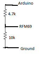
-
I am still having some problems with getting any data from the RFM69.
Do I need to define some pins to like in the NRF24L01 section in the Myconfig.h ?
I have not defined any pins anywhere for the RFM69 or do I not need to do that?/********************************** * NRF24L01 Driver Defaults ***********************************/ #define RF24_CE_PIN 9 #define RF24_CS_PIN 10 #define RF24_PA_LEVEL RF24_PA_MAX #define RF24_PA_LEVEL_GW RF24_PA_LOW // RF channel for the sensor net, 0-127 #define RF24_CHANNEL 76 //RF24_250KBPS for 250kbs, RF24_1MBPS for 1Mbps, or RF24_2MBPS for 2Mbps #define RF24_DATARATE RF24_250KBPS // This is also act as base value for sensor nodeId addresses. Change this (or channel) if you have more than one sensor network. #define RF24_BASE_RADIO_ID ((uint64_t)0xA8A8E1FC00LL) // Enable SOFTSPI for NRF24L01 when using the W5100 Ethernet module //#define SOFTSPI #ifdef SOFTSPI // Define the soft SPI pins used for NRF radio const uint8_t SOFT_SPI_MISO_PIN = 16; const uint8_t SOFT_SPI_MOSI_PIN = 15; const uint8_t SOFT_SPI_SCK_PIN = 14; #endif /********************************** * RFM69 Driver Defaults ***********************************/ // Default network id. Use the same for all nodes that will talk to each other #define RFM69_NETWORKID 100 // Default frequency to use. This must match the hardware version of the RFM69 radio (uncomment one): // #define RFM69_FREQUENCY RF69_433MHZ #define RFM69_FREQUENCY RF69_868MHZ //#define FREQUENCY RF69_915MHZ // Enable this for encryption of packets //#define RFM69_ENABLE_ENCRYPTION #define RFM69_ENCRYPTKEY "sampleEncryptKey" //exactly the same 16 characters/bytes on all nodes!```
Hello! It looks like you're interested in this conversation, but you don't have an account yet.
Getting fed up of having to scroll through the same posts each visit? When you register for an account, you'll always come back to exactly where you were before, and choose to be notified of new replies (either via email, or push notification). You'll also be able to save bookmarks and upvote posts to show your appreciation to other community members.
With your input, this post could be even better 💗
Register Login