Test of Step-Up-Modules (sparkfun, Pololu & china-module) / any other?
-
oki.
but for more low power you need to not use the watchdog. and it is used in gw.sleep.
others tips too are to set unused pins in output mode, and set them = 0 if I remember right. because it consumes too. look at gammon power savings tuto, you will learn interesting things..for your china module, I can't see on pictures what is the reference of the booster ic...then looking at datasheet would tell more.
-
what can i save without the watchdog?
gw.sleep doesnt work without watchdog, i think? what can be a workaround?i found a blog, where someone tested the powersavings by setting the pins to outputmode. This is <1uA. not a big deal...
-
Running Gammon's "Sketch J" drops you down to 150nA, and it doesn't set unused pins to anything.
-
yes of course setting pins mode is the last optimizations. Like Neverdie said, you should try Sketch J.
but you can do all what you want, if your power supply is not good, you will never get <uA.. -
To reach <50uA is the target. I dont need to get nA.
The difference between 100uA and 50uA is the change intervall of the batteries. every year or nearly every 2 years :D
I will take a look at "Sketch J"....sound interesting... -
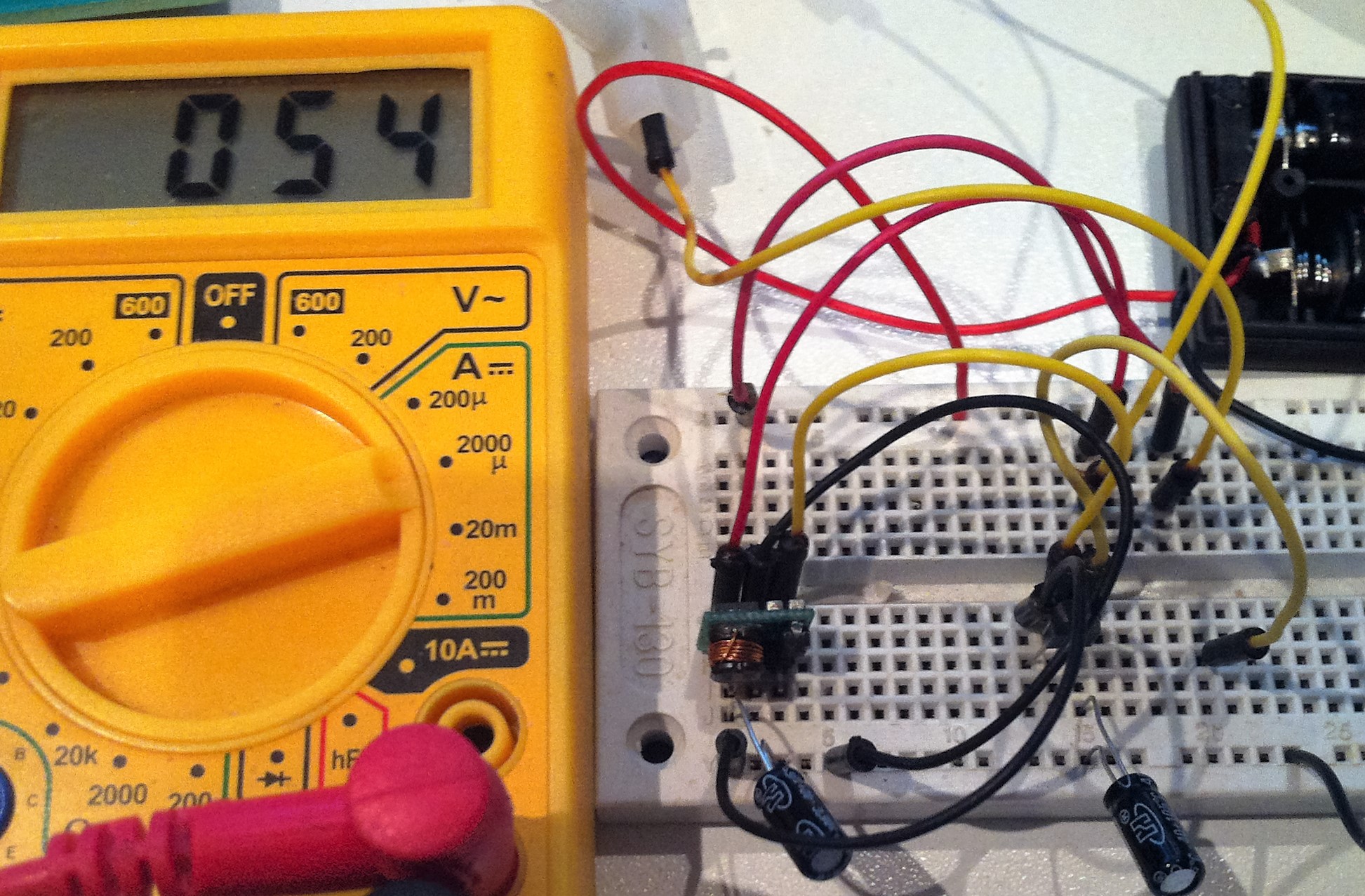
Just took the time to shoot a pic of my Step-Up consumption, including a Voltage regulator MCP1702-3.3
As you can see, it's consuming 54uA with nothing connected.
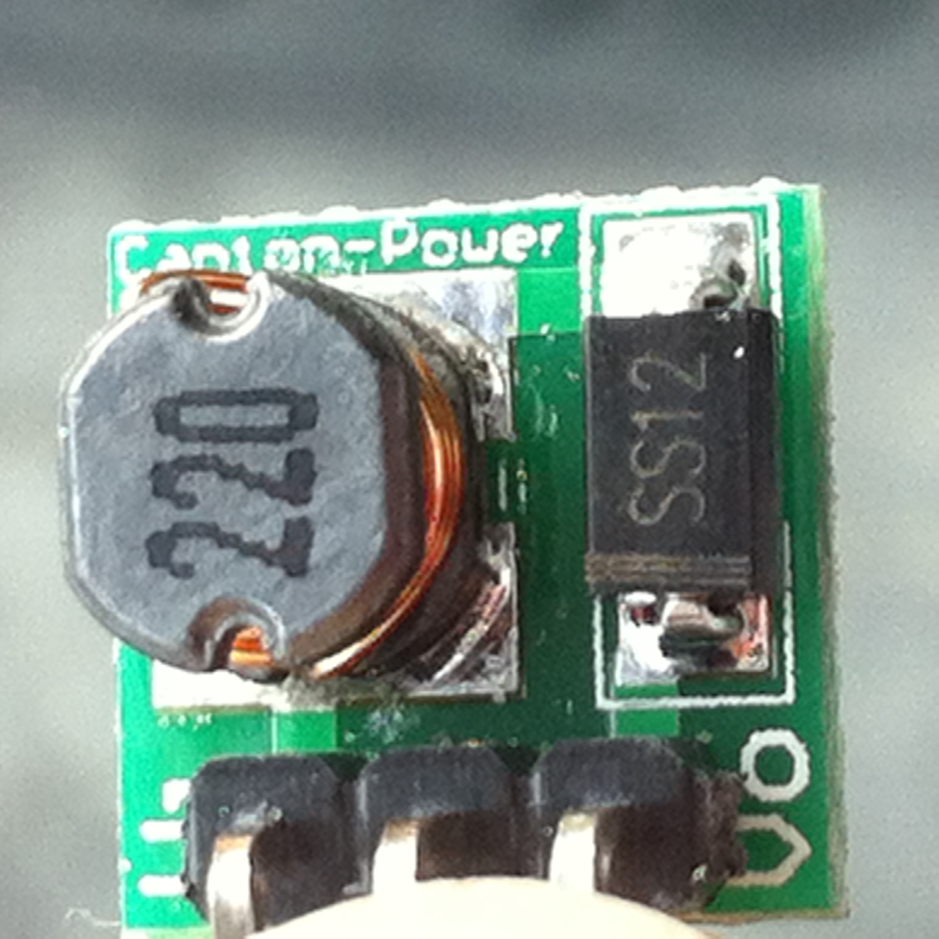
Step-Up module: link
The capacitors are really important, one on the input of the step-up module, the other on the output of the MCP1702-3.3, both are 22uF. Without them, consumption is 2.20mA
-
Reading this thread again makes me remember another observation I did when was trying to get my mini PIR sensor up and running.
I was measuring load current and switched between the old "big" china step-up and the now more common smaller sized one. Identical load. The sleep current was a lot more for the newer smaller one. Could have been those 240uA, not sure but I remember it was the double or something. I was really confused since the two boards look to be populated with the same componets. I didn't look into this further cause I could bearly make the PIR stable on boost supply in any way.
Edit. Power Led disabled, of course.
-
On my custom node PCB, I will use MCP16251 chip to boost supply to 3.3V.
http://ww1.microchip.com/downloads/en/DeviceDoc/25173A.pdfBy docs, If I use it from one AA battery (1.5V), the efficiency is ~80%, consumes ~14uA. I think it is not bad.
-
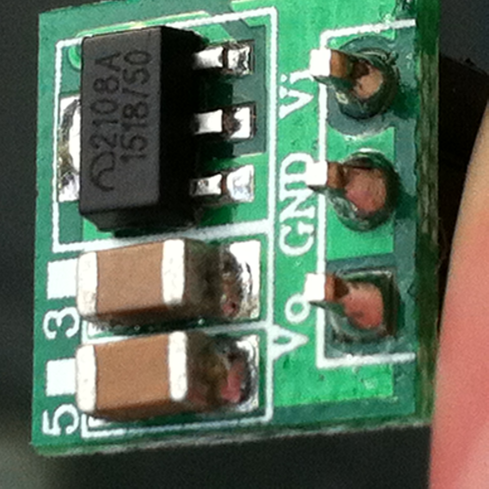
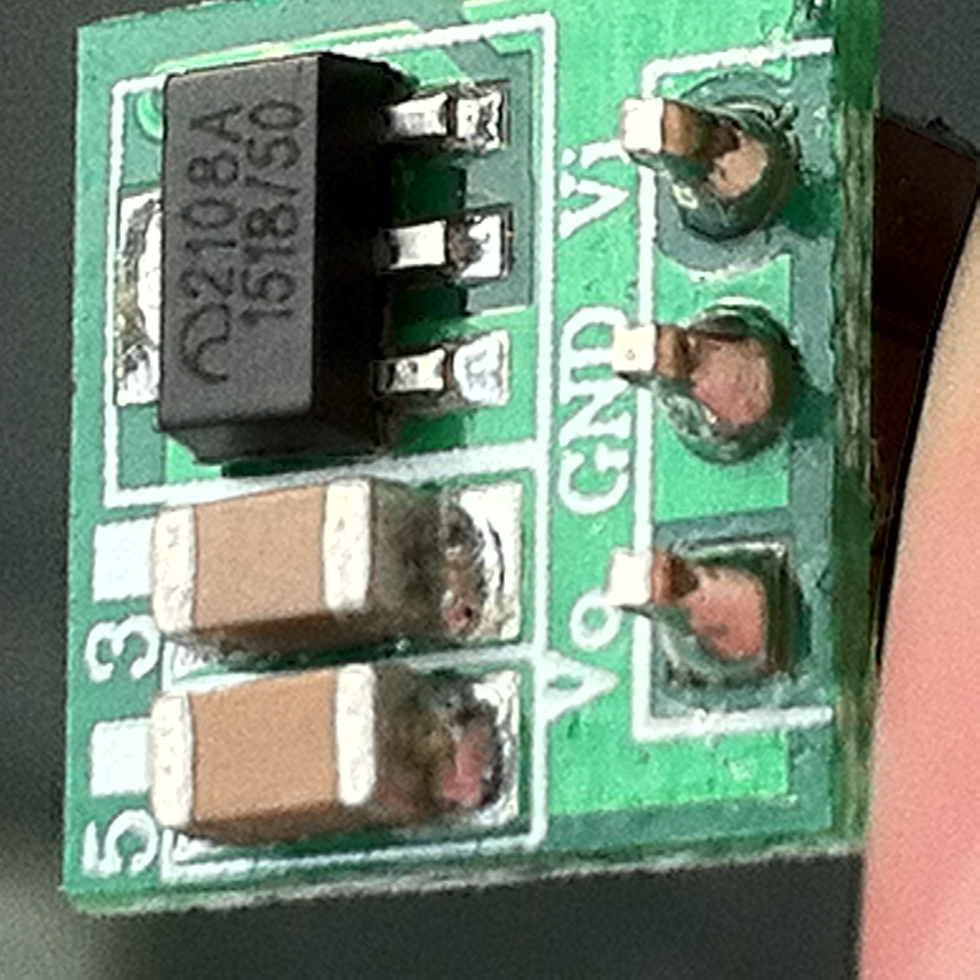
@ericvdb great observation. But this board is not an MCP1702, because MCP1702 is a voltage regulator IC
-
Just took the time to shoot a pic of my Step-Up consumption, including a Voltage regulator MCP1702-3.3
As you can see, it's consuming 54uA with nothing connected.
Step-Up module: link
The capacitors are really important, one on the input of the step-up module, the other on the output of the MCP1702-3.3, both are 22uF. Without them, consumption is 2.20mA
-
Hi.
maybe it could help some people to "evaluate theoretical" quiescent current...
if I remember right (I am not in front of my stuff), we can calculate the theoretical power consumption at Input like this:
I_input = (Vout * I_circuit)/(Vbat * Eff)
where
I_input = power consumption at Input
Vout = booster voltage output
I_circuit = power consumption of the circuit
Vbat = battery voltage
Eff = booster efficiency for Vout and VbatNow, if we take MCP1651, and says we have:
- a circuit which consumes 50uA (including booster quiescent current, sensors, leakage and a well designed circuit...)
- a MCP16251 booster with 3.3V output on a single 1.5V cell. Efficiency won't be the same during the whole life. And it is not an ultra high efficiency booster or it it would be named like "ultra high" (when they can, they do advertisement ;) ). This is why we can only see the efficiency at 1mA. But what is efficiency under very light loads (<100uA)? It should need to be tested. no matter, we assume it is like on datasheet.
So here we have Eff=85% at VIN=1.5V and Eff=80% at 0.9V (near end of life)
Some maths gives us:
I_input = (Vout * I_circuit)/(Vbat * Eff)
I_input = (3.3V * 50uA)/(1.5V * 0.85)
I_input= 129uA
So it should use approximatively 129uA at Input/batt.Another maths, if batt is at the end of life:
I_input = (3.3V * 50uA)/(0.9V * 0.80)
I_input= 229uASo here we can see that quiescent current of booster is not always the biggest problem.
I hope it can help in your choice. And I hope to have not done a mistake lol!
-
This guy has actually tested the mcp16251 and posted his findings on YouTube https://m.youtube.com/watch?v=O5o6JUjz6Yc
Hello! It looks like you're interested in this conversation, but you don't have an account yet.
Getting fed up of having to scroll through the same posts each visit? When you register for an account, you'll always come back to exactly where you were before, and choose to be notified of new replies (either via email, or push notification). You'll also be able to save bookmarks and upvote posts to show your appreciation to other community members.
With your input, this post could be even better 💗
Register Login