Multisensor node using Ceech board
-
@ceech I have the same problem with the LTC4079 board:
Running a simplified sketch gives the following:
Vcc = 3.39V
Charge current = 2.26mA
Solar cell voltage = 5.40V
Battery voltage = 4.11V
CHRG = 502


Vcc = 3.42V
Charge current = 0.25mA
Solar cell voltage = 5.41V
Battery voltage = 4.11V
CHRG = 500

Vcc = 3.35V
Charge current = 0.00mA
Solar cell voltage = 5.24V
Battery voltage = 4.11V
CHRG = 498

Vcc = 3.33V
Charge current = 0.00mA
Solar cell voltage = 5.19V
Battery voltage = 4.08V
CHRG = 496
CHRG is never goes to zero or close and the charging current is low or zero. Shall I try to adjust the same potentiometer as above?
-
If the trimmer is in the same position as when new, then yes. Turn it anti-clockwise to reach its minimum value. Either that or raise the input voltage to 11V.
-
This is a one turn trimmer. Its minimum value is close to 5V mark on one of the above pictures. And its maximum value is next to 18V mark. Since you've turned it more than once, you have to first determine the current wiper position. If you look closely you can see that the turning top is not quite round. One side is a bit flattened. That is the opposite side of the wiper. Now if you take a look at your picture then I think your wiper position is at around 6 or 7V ( to use the same terminology). I would say 20 more degrees to the left and you'll reach 5V.
You can also measure the trimmer's resistance. Like so
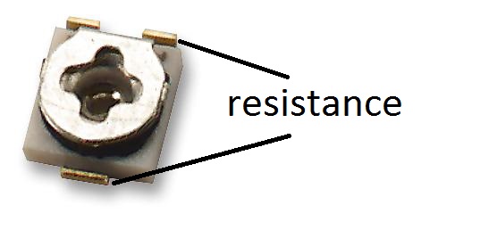
Find the minimum value between marked points. That is your target resistance value. -
@ceech - many thanks for above.
I think I nailed it finally.
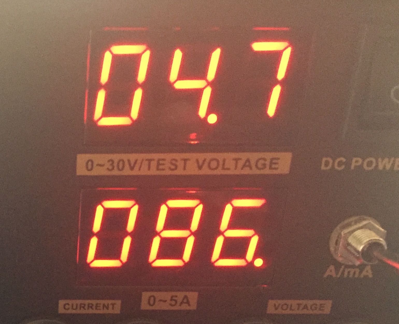
Is the voltage below normal or can that be adjusted somehow?Vcc = 3.35V Charge current = 34.22mA Solar cell voltage = 4.55V Battery voltage = 3.80V CHRG = 446 Vcc = 3.39V Charge current = 31.87mA Solar cell voltage = 4.72V Battery voltage = 3.78V CHRG = 451When does analogue A7 (CHRG) go down to zero or around zero?
-
What voltage would you like to adjust?
The current is a bit low. What is your panel's maximum available current?
The charger is not operating at its full power. Either you are a bit high with the setting on the trimmer or the panel can't supply enough. Charging current should be around 90mA. -
@ceech The solar panal is 6V 4.5W, but right now it is used inside under my table lamp hence a lower voltage (4.7V). I'll to put it in the sun once the weather improves to test it.
EDIT: I have not tested the solar panel before in the sun. Obviously, it provides ~4.8V inside and not sure if it will provide closer to 6v in the sun. I purchased it here http://www.ebay.co.uk/itm/281945297221
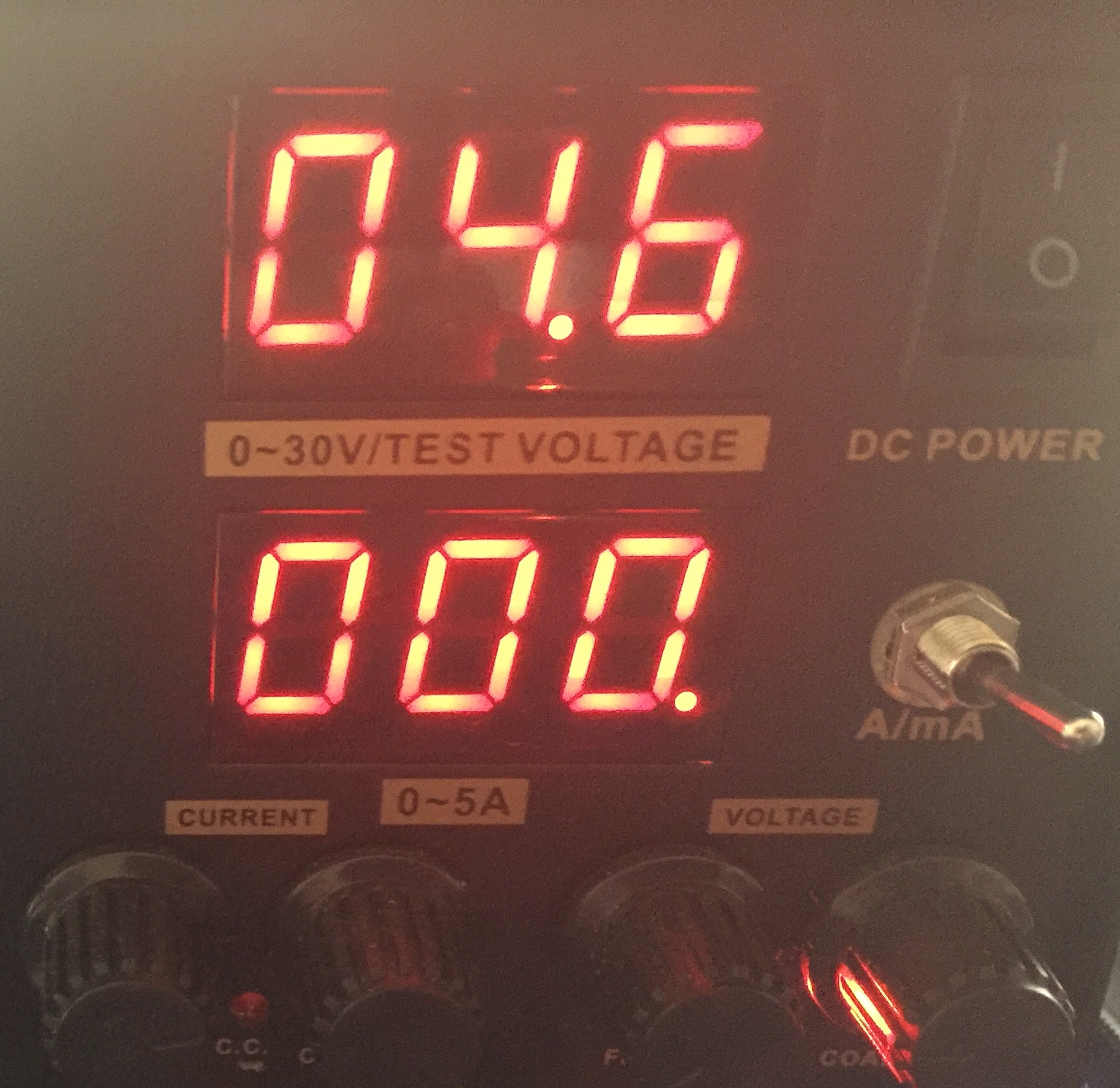
Can I connect 5.5v power supply to the 'solar cell' contacts from a reliable PSU to test the trimmer settings ?
-
@ceech The solar panal is 6V 4.5W, but right now it is used inside under my table lamp hence a lower voltage (4.7V). I'll to put it in the sun once the weather improves to test it.
EDIT: I have not tested the solar panel before in the sun. Obviously, it provides ~4.8V inside and not sure if it will provide closer to 6v in the sun. I purchased it here http://www.ebay.co.uk/itm/281945297221
Can I connect 5.5v power supply to the 'solar cell' contacts from a reliable PSU to test the trimmer settings ?
-
Sure use your power supply. No problem. If the solar cell is 6V, than leave the trimmer. I think you got it just right.
And you were getting 30mA INDOORS? That's great. I'm quite pleased with that information.
This means that this sensor board can also be used as Indoors solar harvester. -
@ceech yes, 30ma indoor, but it is under a direct light. The cut-off voltage is around 4.7V for charging.
-
@alexsh1 You are at the minimum then. The trimmer was calculated for 4.75V minimum voltage. You might want to raise it a little to get 5.5V-6V MPPT.
-
@ceech Ok, but what's the tolerance please? I do want the threashhold to be at the minimum level, but meantime I do not want to damage LTC4079.
-
@alexsh1 No need to worry about minimum voltage destroying the IC. It is just necessary for the battery to receive full charge that the input voltage is within 4.75V and 20V.
-
@ceech Ok so if I have a sunny day and the solar panel is providing 6V, but I have 4.75V MPPT set as a minimum, there is no problem?
-
Hi ceech,
first things first: I have a really small knowledge about charging batteries.
Could you give me a hint how to adopt the floating voltage for a NiCd battery?
By reading the datasheet I only found NiMh with a 3kOhm PROG resistor while yours is 1180Ohm. Do I have to modify him to lower the charge current?
And how about the timer capacitor. I red, that NiCd shouldn't charged too long. You pulled TIMER to ground, so the device will charge forever?Maybe this problem is solved by the sunset itself?
Again thanks for your contribution!
-
The float, or better cut-off voltage for NiCd batteries is between 1.5V and 1.6V per cell.
Programming resistor of 3k equals to 100mA of charging current and 1180 ohm equals to 250mA, which is a maximum value that the LTC4079 can handle (it gets too hot at this value). I equip the boards with 3k resistors.
Batteries can be charged with different currents. One option is 0.1C (the C rate is the hour capacity of the battery). That is 10% of battery's nominal value. For 1000mAh battery that would mean 100mA.
I pulled timer to ground which means that the charger will stop charging at C/10 or 10% of programmed current, or 10mA in case where a 3k resistor is used. This works fine for lithium batteries.
NiCd or NiMH batteries should be charged with timer limit as you mention. It is not absolutelly necessary in our case. Let me explain. If you charge a NiCd battery with a 0.1C, that means that the battery will be fully charged in approximately 14 hours. So the sunset will be the timer that we need. And even if we charge the battery all the time a C/10 termination will reduce the charging current to a value which is close to a battery's self-discharge rate, thus keeping the battery voltage on safe levels.
There is also battery voltage monitoring circuit on the board which can be used to report whenever the battery voltage is out of bounds.
Hello! It looks like you're interested in this conversation, but you don't have an account yet.
Getting fed up of having to scroll through the same posts each visit? When you register for an account, you'll always come back to exactly where you were before, and choose to be notified of new replies (either via email, or push notification). You'll also be able to save bookmarks and upvote posts to show your appreciation to other community members.
With your input, this post could be even better 💗
Register Login