Multisensor node using Ceech board
-
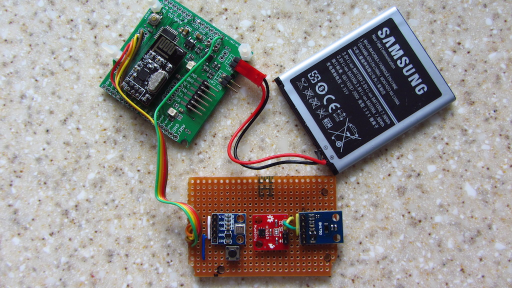
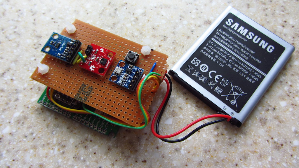
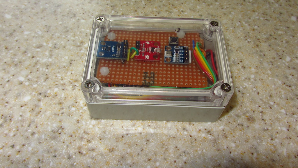
Here are some pics of my multisensor node, using the Ceech board with lithium battery charger. The stripboard houses - from left to right - a BMP180, HTU21D and BH1750FVI. As you can see, I've soldered radio and connections directly to the board, to reduce height in order to fit the box.
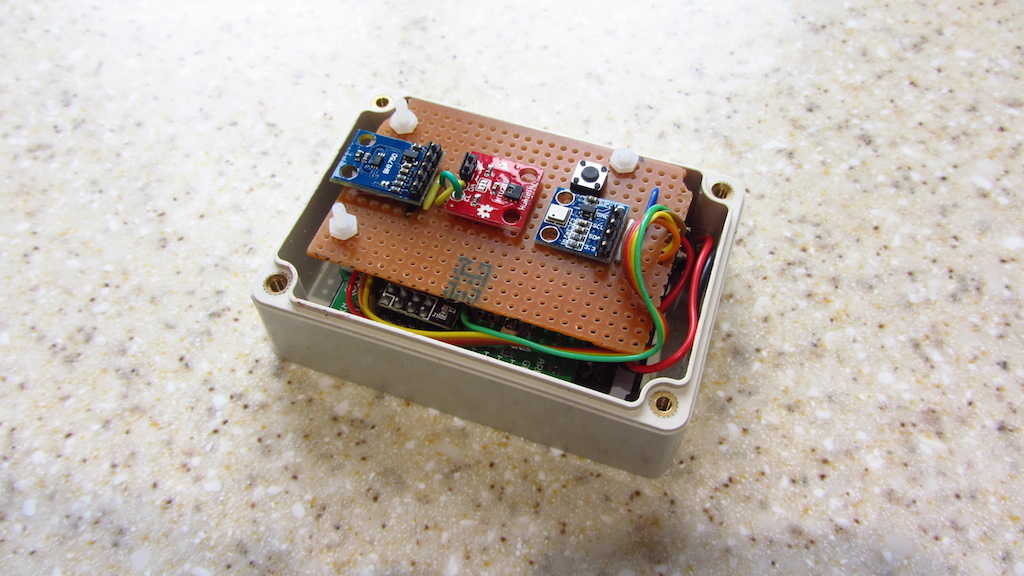
The box is the same as the one shown here:
(http://www.ebay.com/itm/85x58x33mm-Waterproof-Cover-Clear-Plastic-Electronic-Project-Box-Enclosure-CASE-/281390875149?hash=item418434020d)(but purchased from UK eBay website).
I had to shave the board down by about 1-2mm on one edge, to fit the box - sorry, Ceech!
-
Here are some pics of my multisensor node, using the Ceech board with lithium battery charger. The stripboard houses - from left to right - a BMP180, HTU21D and BH1750FVI. As you can see, I've soldered radio and connections directly to the board, to reduce height in order to fit the box.
The box is the same as the one shown here:
(http://www.ebay.com/itm/85x58x33mm-Waterproof-Cover-Clear-Plastic-Electronic-Project-Box-Enclosure-CASE-/281390875149?hash=item418434020d)(but purchased from UK eBay website).
I had to shave the board down by about 1-2mm on one edge, to fit the box - sorry, Ceech!
-
@Dwalt I cut a slot in one end of the box; I intend to use it outdoors, mounted vertically, so that the slot is at the bottom.
The button is a reset button, wired to the RESET connection on the Ceech board. I made a small hole in the lid (covered with Sellotape!), so that I can insert a pin / paper clip to press it. -
I just love to see that you find those boards useful.
Nice work. -
Here's the code I've used - it's based on Ceech's sketch for the board, with the addition of code for the BH1750:
/* PROJECT: MySensors / LiON charger board PROGRAMMER: AWI DATE: 28 april 2015/ last update: 11 may 2015 / BH1750 added: 5 September 2015 FILE: MS_Solar_2.ino LICENSE: Public domain Hardware: Ceech - ATmega328p board w/ ESP8266 and NRF24l01+ socket LTC4067 lithium battery charger and MySensors 1.4 Temp & Humidity - HTU21 Barometer & Temp - BMP085 Light sensor - BH1750 On board EEPROM (I2C) On board Li-On charger with multiple V/A measurements Special: program with Arduino Pro 3.3V 8Mhz SUMMARY: Reads on-board sensors and send to gateway /controller Remarks: On board EEPROM and MOSFET not used in this sketch Fixed node-id */ #include <SPI.h> #include <MySensor.h> #include <Wire.h> // I2C #include <HTU21D.h> // temperature / humidity (i2c, HTU21D, SHT21) #include <Adafruit_BMP085.h> // barometer / temperature #include <BH1750.h> #define LTC4067_CHRG_PIN A1 //analog input A1 on ATmega 328 is /CHRG signal from LTC4067 #define batteryVoltage_PIN A0 //analog input A0 on ATmega328 is battery voltage ( /2) #define solarVoltage_PIN A2 //analog input A2 is solar cell voltage (/ 2) #define solarCurrent_PIN A6 //analog input A6 is input current ( I=V/Rclprog x 1000 ) #define batteryChargeCurrent_PIN A7 //analog input A7 is battery charge current ( I=V/Rprog x 1000 ) #define LTC4067_SUSPEND_PIN 9 //digital output D9 - drive it high to put LTC4067 in SUSPEND mode const float VccMin = 1.0*3.5; // Minimum expected Vcc level, in Volts. Example for 1 rechargeable lithium-ion. const float VccMax = 1.0*4.2; // Maximum expected Vcc level, in Volts. #define TEMPERATURE_CHILD_ID 2 #define TEMP_CHILD_ID 3 #define HUM_CHILD_ID 4 #define BARO_CHILD_ID 5 #define BATT_CHILD_ID 10 #define SOLAR_CHILD_ID 11 #define LIGHT_CHILD_ID 6 HTU21D SHT21; // Hum/Temp (SHT12) Adafruit_BMP085 bmp; // define baro/ temp meter BH1750 lightSensor; // define light sensor MySensor gw(7,8); // Ceech board, 3.3v (pin default 9,10) unsigned long SLEEP_TIME = 60000; // 60 sec sleep time between reads (seconds * 1000 milliseconds) float lastTempSHT; // SHT temp/hum float lastHumSHT; float lastTempBMP; float lastPresBMP; int altitude = 100; // 330 feet above sealevel float lastBattVoltage; float lastBattCurrent; float lastSolarVoltage; float lastSolarCurrent; int lastBattPct = 0; uint16_t lastLux; float VccReference = 3.3 ; // voltage reference for measurement, definitive init in setup MyMessage temperatureMsg(TEMP_CHILD_ID, V_TEMP); // SHT temp (deg C) MyMessage humidityMsg(HUM_CHILD_ID, V_HUM); // SHT hum (% rh) MyMessage pressureMsg(BARO_CHILD_ID, V_PRESSURE); // BMP pressure (hPa) MyMessage batteryVoltageMsg(BATT_CHILD_ID, V_VOLTAGE); // Battery voltage (V) MyMessage batteryCurrentMsg(BATT_CHILD_ID, V_CURRENT); // Battery current (A) MyMessage solarVoltageMsg(SOLAR_CHILD_ID, V_VOLTAGE); // Solar voltage (V) MyMessage solarCurrentMsg(SOLAR_CHILD_ID, V_CURRENT); // Solar current (A) MyMessage luxMsg(LIGHT_CHILD_ID, V_LIGHT_LEVEL); // Light sensor (lux) void setup() { gw.begin(NULL, 19); // fixed node 19 // Send the sketch version information to the gateway and Controller gw.sendSketchInfo("AWI Dev THB/batt 19", "1.0"); gw.present(TEMP_CHILD_ID, S_TEMP); // SHT temp gw.present(HUM_CHILD_ID, S_HUM); // SHT humidity gw.present(BARO_CHILD_ID, S_BARO); // BMP pressure (temp not used here) gw.present(BATT_CHILD_ID, S_POWER); // Battery parameters gw.present(SOLAR_CHILD_ID, S_POWER); // Solar parameters gw.present(LIGHT_CHILD_ID, S_LIGHT_LEVEL); // Light sensor // use VCC (3.3V) reference analogReference(DEFAULT); // default external reference = 3.3v for Ceech board VccReference = 3.323 ; // measured Vcc input (on board LDO) pinMode(LTC4067_SUSPEND_PIN, OUTPUT); // suspend of Lion charger set digitalWrite(LTC4067_SUSPEND_PIN,LOW); // active (non suspend) at start Wire.begin(); // init I2C SHT21.begin(); // initialize temp/hum bmp.begin(); // bmp085 temp/ baro lightSensor.begin(); // light sensor } void loop() { sendTempHum(); Serial.println(); sendTempBaro(); Serial.println(); sendVoltage(); Serial.println(); sendLight(); Serial.println(); gw.sleep(SLEEP_TIME); } void sendTempHum(void) { // SHT2x sensor // Temperature and Humidity float humidity = SHT21.readHumidity(); // send to MySensor network / only if change if (humidity != lastHumSHT && humidity != 0.00) { lastHumSHT = humidity; gw.send(humidityMsg.set(humidity, 2)); // Send } float temperatureSHT = SHT21.readTemperature(); // send to MySensor network / only if change if (temperatureSHT != lastTempSHT && temperatureSHT != 0.00) { lastTempSHT = temperatureSHT; gw.send(temperatureMsg.set(temperatureSHT, 2)); // Send } Serial.print("SHT21 temp: "); Serial.print(temperatureSHT); Serial.print(" SHT21 hum: "); Serial.print(humidity); } void sendTempBaro(void) // Send temperature and barometer from baro sensor (temp1) { float temperature = bmp.readTemperature(); // send to MySensor network / only if change (not sent here) if (temperature != lastTempBMP) { lastTempBMP = temperature; //gw.send(temperatureMsg.set(temperature, 1)); // Send } float pressure = (float)bmp.readSealevelPressure(altitude)/100; // send to MySensor network / only if change if (pressure != lastPresBMP) { lastPresBMP = pressure; gw.send(pressureMsg.set(pressure, 1)); // Send } Serial.print("BMP180 temp: "); Serial.print(temperature); Serial.print(" BMP180 pressure: "); Serial.print(pressure); } void sendVoltage(void) // battery and charging values { // get Battery Voltage & charge current float batteryVoltage = ((float)analogRead(batteryVoltage_PIN)* VccReference/1024) * 2; // actual voltage is double Serial.print("Batt: "); Serial.print(batteryVoltage); Serial.print("V ; "); float batteryChargeCurrent = ((float)analogRead(batteryChargeCurrent_PIN) * VccReference/1024)/ 2.5 * 1000; // current(mA) = V/Rprog(kohm) Serial.print(batteryChargeCurrent); Serial.println("mA "); // get Solar Voltage & charge current float solarVoltage = ((float)analogRead(solarVoltage_PIN)/1024 * VccReference) * 2 ; // actual voltage is double Serial.print("Solar: "); Serial.print(solarVoltage); Serial.print("V ; "); // get Solar Current float solarCurrent = ((float)analogRead(solarCurrent_PIN)/1024 * VccReference)/ 2.5 * 1000; // current(mA) = V/Rclprog(kohm) Serial.print(solarCurrent); Serial.print(" mA; charge: "); Serial.println(digitalRead(LTC4067_CHRG_PIN)?"No":"Yes"); // send battery percentage for node int battPct = 1 ; if (batteryVoltage > VccMin){ battPct = 100.0*(batteryVoltage - VccMin)/(VccMax - VccMin); } Serial.print("BattPct: "); Serial.print(battPct); Serial.println("% "); gw.send(batteryVoltageMsg.set(batteryVoltage, 3)); // Send (V) gw.send(batteryCurrentMsg.set(batteryChargeCurrent, 6)); // Send (mA) gw.send(solarVoltageMsg.set(solarVoltage, 3)); // Send (V) gw.send(solarCurrentMsg.set(solarCurrent, 6)); // Send (mA) gw.sendBatteryLevel(battPct); } void sendLight(void) // Send light level - BH1750 { uint16_t lux = lightSensor.readLightLevel(); if (lux != lastLux) { gw.send(luxMsg.set(lux)); // Send lastLux = lux; } Serial.print("BH1750 lux: "); Serial.print(lux); } /* Ceech board specifics for reference: It provides power for the circuit and charges the backup single-cell lithium battery while greatly extends battery life. You can monitor the voltages and currents. It has suspend mode, which reduces current consumption to around 40μA. The power source is a small, 5V solar cell. Connections: analog input A1 on ATmega 328 is /CHRG signal from LTC4067 (indicates fully charged) analog input A0 on ATmega328 is battery voltage analog input A2 is solar cell voltage analog input A6 is input current ( I=V/Rclprog x 1000 ) analog input A7 is battery charge current ( I=V/Rprog x 1000 ) digital output D9 - drive it high to put LTC4067 in SUSPEND mode All the voltages on analog inputs can be read with an analogRead() command in the Arduino IDE sketch. Those on inputs A0 an A2 represent direct values of the measured voltages divided by 2. The voltages on analog inputs A6 and A7 can be translated to currents. For example: Let us say that the voltage on A7 is 0.12V. And the trimmer pot on PROG pin is set to 2.5kOhm. This means that the current into the battery equals to 0.12V/2500ohm x 1000, which is 48mA. voltmeters on both battery and solar cell connections They are connected to analog inputs A0 and A2 on the ATmega328p. The voltage dividers resistors are equal, so the measured voltage is double the shown voltage. NRF24l01+ socket with CE and CSN pins connected to digital pins 7 and 8 ( you use RF24 radio(7, 8); in Arduino code). There is a 4.7uF capacitor connected across Vin and GND of the port */ -
Hi,
It works great! Thanks!
Did you tune the potentiometers, or left as they were?I'm using 2x 6v, 100mA solar panels in parallel and one 5000mAh Li-ion battery.
EDIT:
Now in a sunny day, it seems something is missing (probably some tuning in the potentiometers). Somehow the battery is not charging:Batt: 3.73V ; 1.30mA Solar: 6.64V ; 0.00 mA; charge: No BattPct: 33% send: 19-19-0-0 s=10,c=1,t=38,pt=7,l=5,st=ok:3.732 send: 19-19-0-0 s=10,c=1,t=39,pt=7,l=5,st=ok:1.298047 send: 19-19-0-0 s=11,c=1,t=38,pt=7,l=5,st=ok:6.640 send: 19-19-0-0 s=11,c=1,t=39,pt=7,l=5,st=ok:0.000000 send: 19-19-0-0 s=255,c=3,t=0,pt=1,l=1,st=ok:33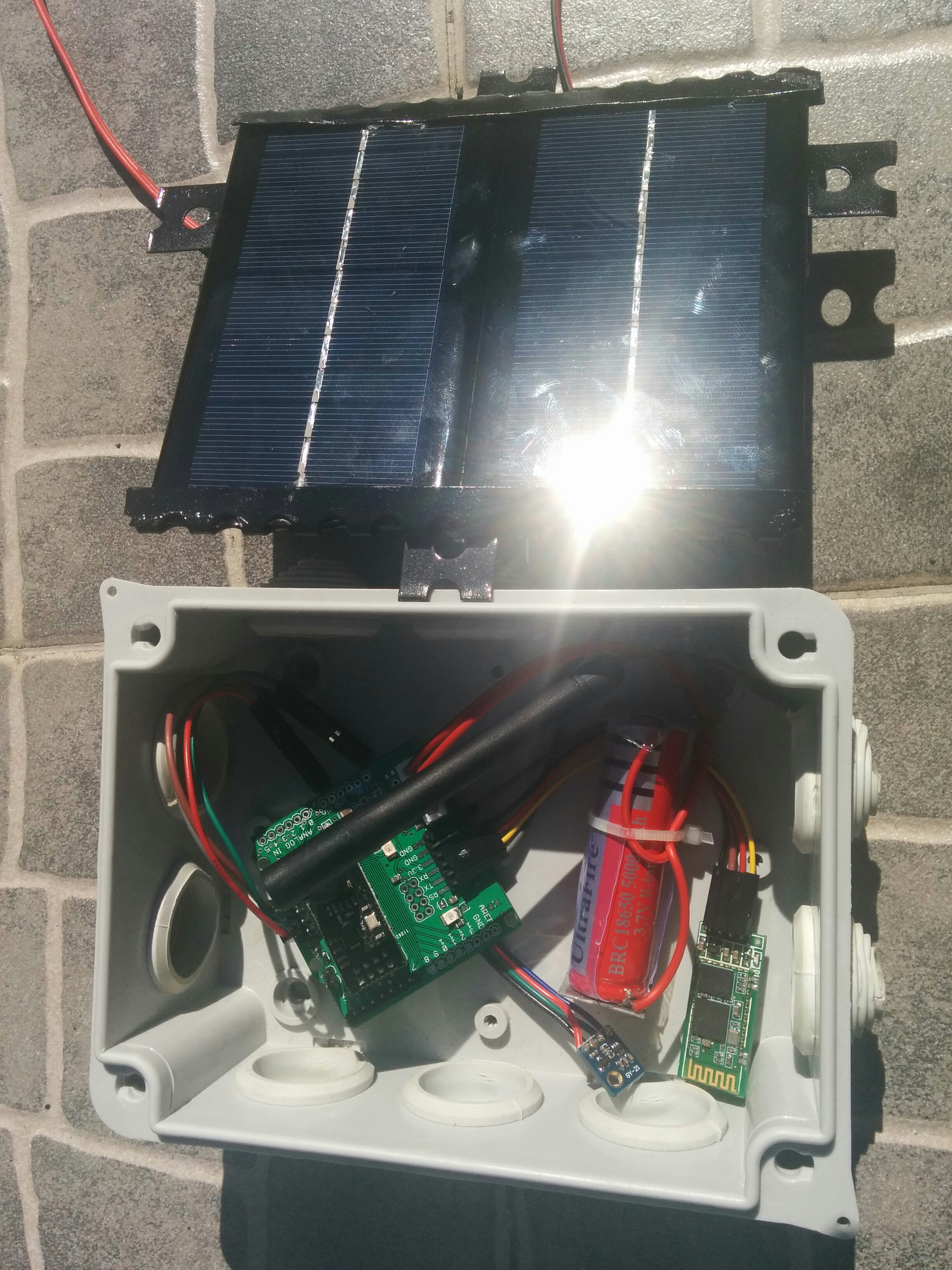
Any idea/suggestion?
Thanks!
Joao -
@joaoabs Glad you got it working.
No, I didn't tune the pots.
I had similar problems with solar panels: battery didn't seem to be charging. Also, you're getting a high solar voltage (6.64V) on a sunny day, as I did. I was concerned, as the absolute max Vin for the LTC4067 - from the datasheet, if I remember correctly - is 6.2V.
I gave up using solar cells, and I'll just charge the battery from a USB charger when I need to.
-
Thanks for the feedback.
I think the key here is in the potentiomenters, so I looked around for some guidance:
The two trimmer potentiometers are used to determine the current for both the input side - to better match the internal resistance of the solar cell - and for the battery charge current. At shipping they are both set to around half the value ( 2.5kOhm), which set both currents to about 75mA.I don't know how to measure the internal resistance of the solar cell (shouldn't be as simple as measuring it with a ohmmeter, right?), but I'm assuming that if 75mA is half the value, the maximum should be 150mA. Since my panels in parallel can supply (theoretically) up to 200mA, I'll rotate the potentiomenter to its maximum. Now, wich potentiomenter is it (not identified in the board), and what to tune in the other potentiometer (should be the same mA, what does it depend on)?
@Ceech, Any guidance on how to overcome this not-charging problem?
Thanks,
Joao -
Thanks for the feedback.
I think the key here is in the potentiomenters, so I looked around for some guidance:
The two trimmer potentiometers are used to determine the current for both the input side - to better match the internal resistance of the solar cell - and for the battery charge current. At shipping they are both set to around half the value ( 2.5kOhm), which set both currents to about 75mA.I don't know how to measure the internal resistance of the solar cell (shouldn't be as simple as measuring it with a ohmmeter, right?), but I'm assuming that if 75mA is half the value, the maximum should be 150mA. Since my panels in parallel can supply (theoretically) up to 200mA, I'll rotate the potentiomenter to its maximum. Now, wich potentiomenter is it (not identified in the board), and what to tune in the other potentiometer (should be the same mA, what does it depend on)?
@Ceech, Any guidance on how to overcome this not-charging problem?
Thanks,
Joao@joaoabs Try lowering input voltage. The IC is in overvoltage mode and we don't want to damage it. Next, try with 5V input. See if you get the charge.
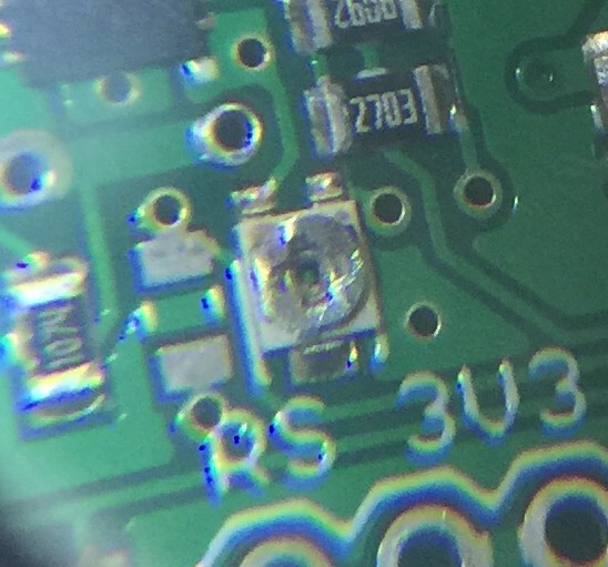
The trimmer potentiometers:
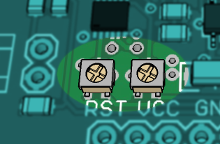
The left one is battery charge current limit. Turn it to the left in order to maximize charging current.
And the right one is input current limit. Keep the input current below solar panel maximum current. Turn it left to increase current limit.This is a formula to calculate input current: Ilim = 200V/Rclprog , where Rclprog stands for trimmer resistance.
And this is how you calculate charging current: Ich = 1000V/Rprog, where Rprog stands for trimmer resistance. It is also limited with input current. -
@ceech I'm using a more recent version of this board, with an LTC4079 charger (instead of the LTC4067).
Which Arduino pin is the ~CHRG signal brought out on? A2 appears to be Vin (solar cell), whereas if I do analogRead(A7) I get a value around 500 (regardless of whether Vin is connected or not)?
-
~CHRG is at ADC A7. It pulls low when the battery is getting charged. It's not always zero, sometimes is stuck around 10 or below. It works in conjunction with ADC A6, which is a battery current pin. Do you get any reports here?
-
@ceech I've connected a 5V USB supply to the solar cell input, and I'm running your example sketch from your eBay web page for this board. I'm seeing a battery voltage of 3.59V (Li-ion), and charge current (monitoring A6) of 0.00mA - suggesting the battery isn't charging? As said before, A7 is showing values around 479.
Vcc = 3.30V
Charge current = 0.00mA
Solar cell voltage = 4.98V
Battery voltage = 3.59V
CHRG = 479 -
Ah, yes. I think i know what the problem is. The LTC4079 has a built-in MPPT power tracking for solar panels and won't charge if the input voltage is below set point. This helps optimizing power extraction from solar panels. If you are using 5V input, then you should adjust the trimmer pot on the board. Like this
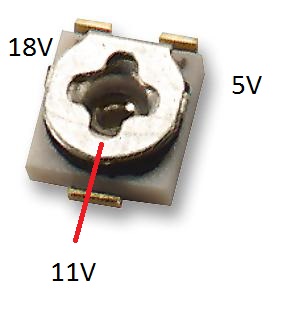
Turn the top round part of the trimmer to the left so that the wiper reaches 5V mark like on the above picture. In other words reduce trimmer resistance to minimum. The other way around is for 18V solar panels. -
@ceech I have the same problem with the LTC4079 board:
Running a simplified sketch gives the following:
Vcc = 3.39V
Charge current = 2.26mA
Solar cell voltage = 5.40V
Battery voltage = 4.11V
CHRG = 502


Vcc = 3.42V
Charge current = 0.25mA
Solar cell voltage = 5.41V
Battery voltage = 4.11V
CHRG = 500

Vcc = 3.35V
Charge current = 0.00mA
Solar cell voltage = 5.24V
Battery voltage = 4.11V
CHRG = 498

Vcc = 3.33V
Charge current = 0.00mA
Solar cell voltage = 5.19V
Battery voltage = 4.08V
CHRG = 496
CHRG is never goes to zero or close and the charging current is low or zero. Shall I try to adjust the same potentiometer as above?
-
If the trimmer is in the same position as when new, then yes. Turn it anti-clockwise to reach its minimum value. Either that or raise the input voltage to 11V.
-
This is a one turn trimmer. Its minimum value is close to 5V mark on one of the above pictures. And its maximum value is next to 18V mark. Since you've turned it more than once, you have to first determine the current wiper position. If you look closely you can see that the turning top is not quite round. One side is a bit flattened. That is the opposite side of the wiper. Now if you take a look at your picture then I think your wiper position is at around 6 or 7V ( to use the same terminology). I would say 20 more degrees to the left and you'll reach 5V.
You can also measure the trimmer's resistance. Like so
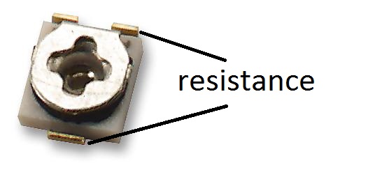
Find the minimum value between marked points. That is your target resistance value.