Skip to content
  • MySensors
  • OpenHardware.io
  • Categories
  • Recent
  • Tags
  • Popular
Skins
  • Light
  • Brite
  • Cerulean
  • Cosmo
  • Flatly
  • Journal
  • Litera
  • Lumen
  • Lux
  • Materia
  • Minty
  • Morph
  • Pulse
  • Sandstone
  • Simplex
  • Sketchy
  • Spacelab
  • United
  • Yeti
  • Zephyr
  • Dark
  • Cyborg
  • Darkly
  • Quartz
  • Slate
  • Solar
  • Superhero
  • Vapor

  • Default (No Skin)
  • No Skin
Collapse
Brand Logo
  1. Home
  2. My Project
  3. 2AA Sensor Board + RPI Gateway + RGBW Dimmer

2AA Sensor Board + RPI Gateway + RGBW Dimmer

Scheduled Pinned Locked Moved My Project
30 Posts 12 Posters 22.8k Views 17 Watching
  • Oldest to Newest
  • Newest to Oldest
  • Most Votes
Reply
  • Reply as topic
Log in to reply
This topic has been deleted. Only users with topic management privileges can see it.
  • scalzS scalz

    cool.
    just for curiosity, did you calculated all res tied to gnd, like dividers, sort of low power killers? Is it your bus current data?

    M Offline
    M Offline
    Myna
    wrote on last edited by
    #10

    @scalz said:

    cool.
    just for curiosity, did you calculated all res tied to gnd, like dividers, sort of low power killers? Is it your bus current data?

    Not yet. I'll use the biggest possible values to loose as few as possible power in theses...

    I'm thinking of wiring the supply of the flash memory chip on the CS. So, the chip will only be powered when selected on the spi bus. Easy mod, because the CS is already there (not the same with I2C...)

    1 Reply Last reply
    0
    • M Offline
      M Offline
      Myna
      wrote on last edited by Myna
      #11

      Hi !

      Some news:

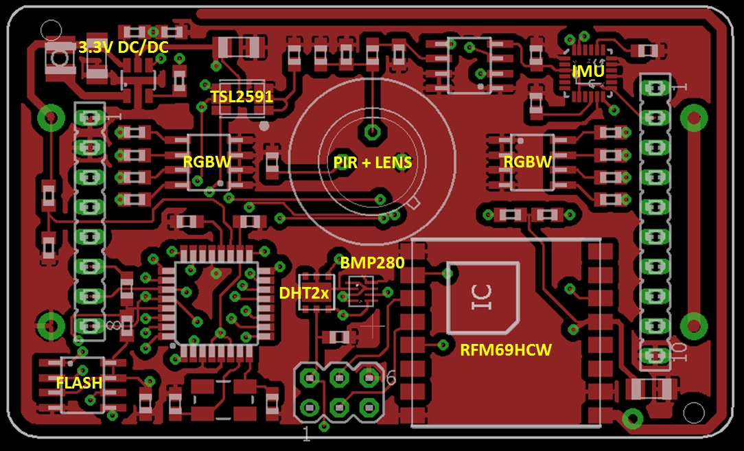
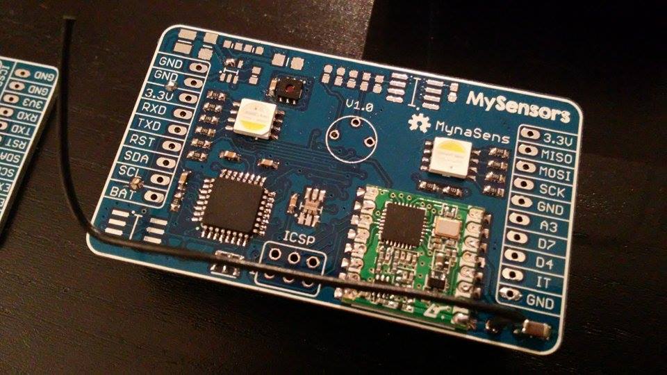
      I've finished the drawing of V1.0. The main change is the following: Pressure sensor and IMU removed. The idea of this board is to be the universal sensor, and make it multiple time. I couldn't really find an use for these sensors. If I need them, it will be on one board, and so a little extension board is OK. Also, it save a bit of space for cleaner routing.

      So it will be Movement/Light/Temp/Humidity/RGBW LEDs/ (Extensions)

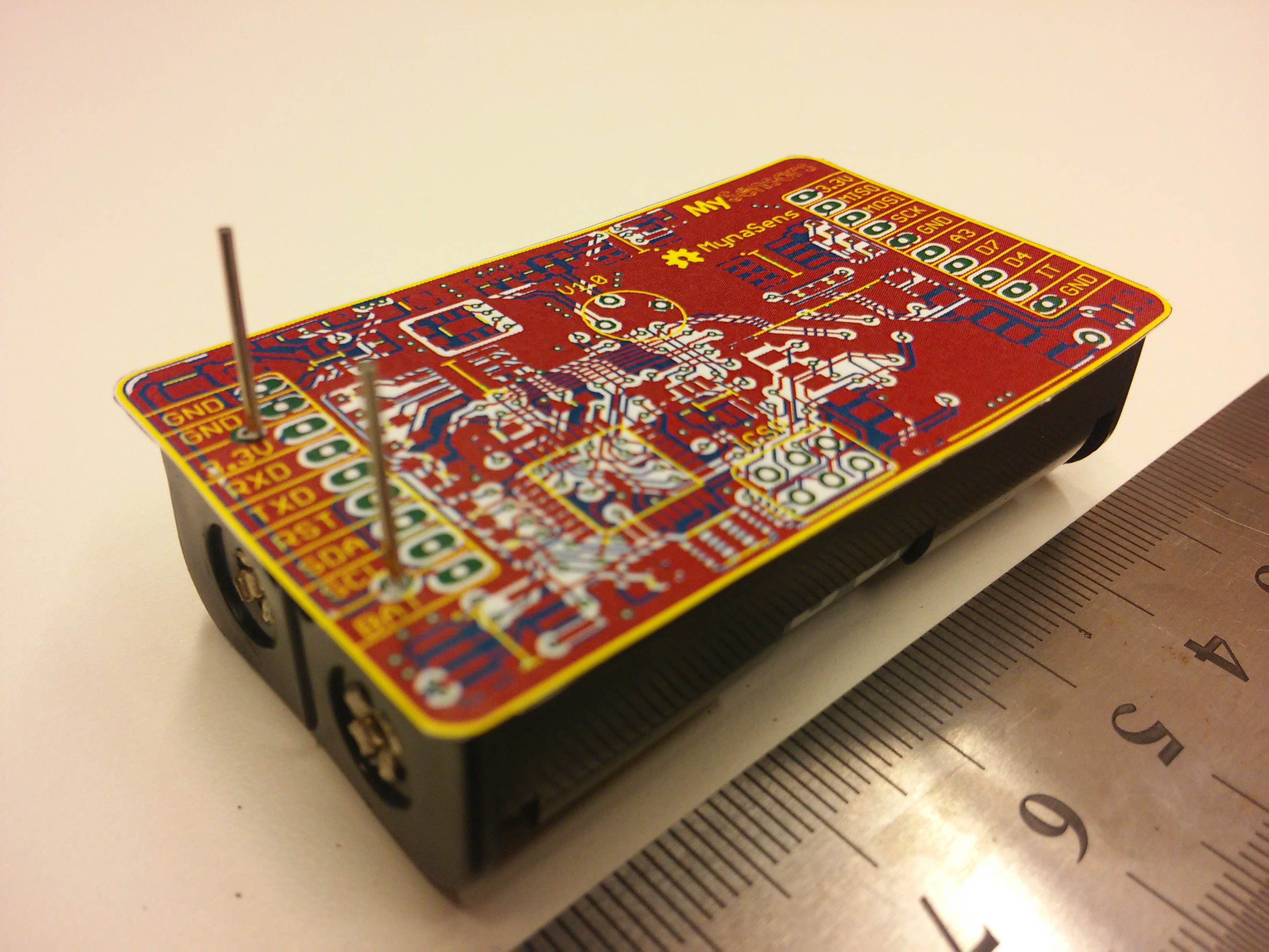
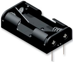
      The board size is 35*60mm, the idea is to solder this model of battery holder under it: 42767313.jpg

      I've started to order some of the components. I didn't ordered PCBs since 2013, is Seeed/Itead still the way to go for cheap good PCBs ?

      The board:

      mynaV1.jpg

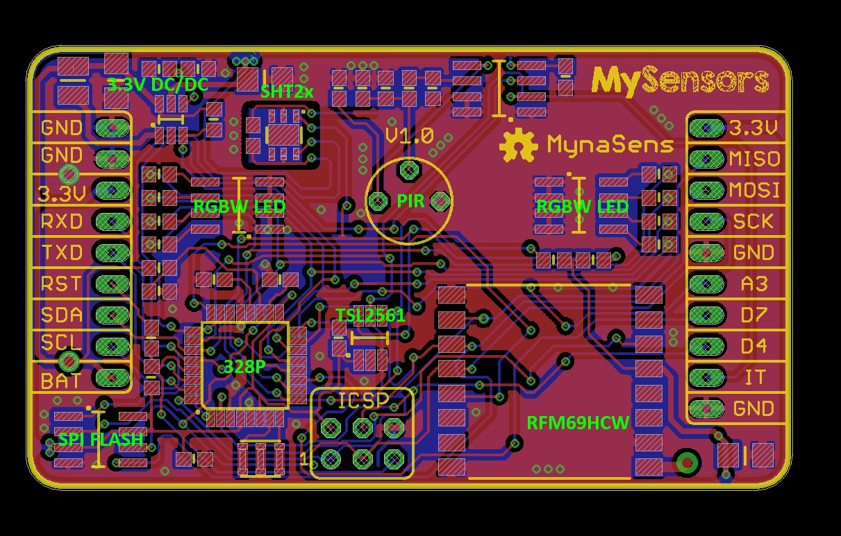
      Silkscreen is in yellow. Is it OK to use the logo of MySensors as I did ? I prefer to be sure...

      Myna

      1 Reply Last reply
      1
      • GertSandersG Offline
        GertSandersG Offline
        GertSanders
        Hardware Contributor
        wrote on last edited by
        #12

        @Myna Very nice board ! As to your question about PCB manufacturing. Seeed/Itead is certainly an option. I have been suprised (in the positive way) by the quality of the boards made by DirtyPCB. It takes a lot of time to get them shipped to Europe, but production quality is good. 14 USD for 10+/-1 boards of 50x50mm is certainly very good value. Your board will probably fall in the 100x100mm category as it exceeds 50mm on one side, but then you could probably panelise it. For 3 PCB samples, and shorter lead time (and any combination of size) I have used OSHPark, but at higher cost.
        Did you make this board in EAGLE or in KiCAD ?

        1 Reply Last reply
        0
        • M Offline
          M Offline
          Myna
          wrote on last edited by
          #13

          Thanks Gert ! It's Eagle 7.3.0 light. Maybe not the best but the one I know... (I have the idea of switching to Altium)

          1 Reply Last reply
          0
          • M Offline
            M Offline
            Myna
            wrote on last edited by
            #14

            IMG_20151120_180219.jpg

            1 Reply Last reply
            0
            • M Offline
              M Offline
              Myna
              wrote on last edited by
              #15

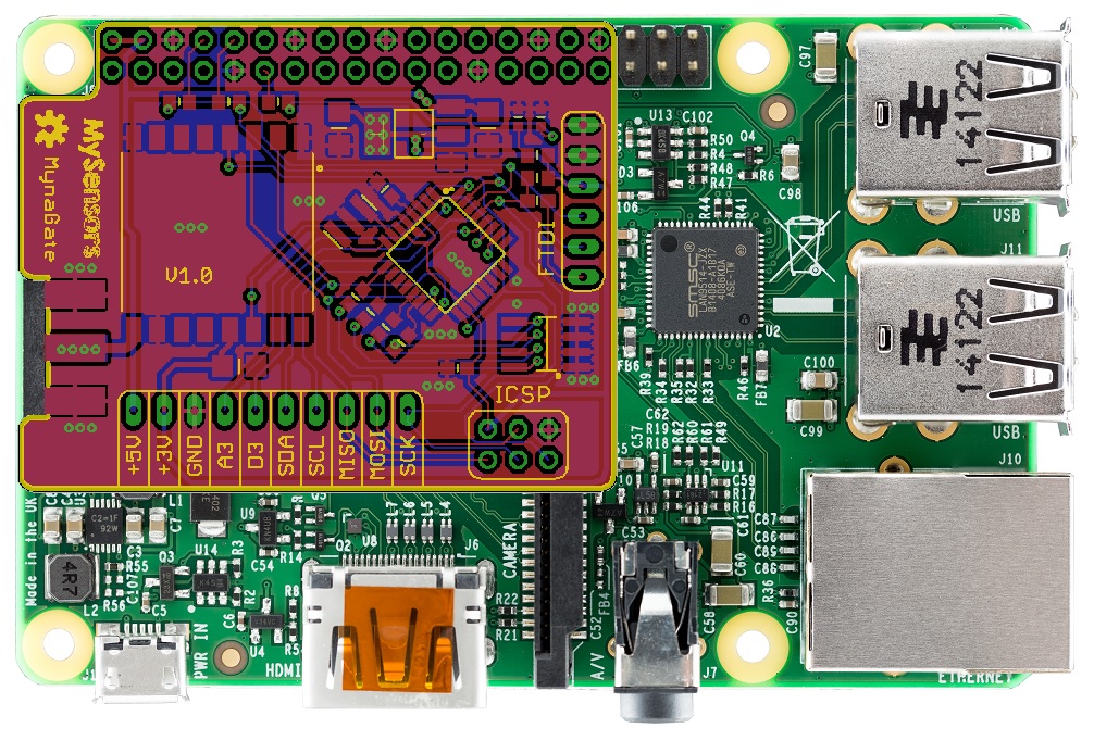
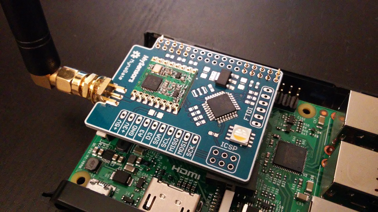
              Hi ! A new board today :

              I don't have any gateway or controller at the moment, and I plan to use Jeedom on a Raspberry Pi 2. So I've routed a little serial gateway for RPI. The board use the native serial port of the RPI (tough it should be more stable than going trough an usb/serial chip ? ). Also, I added a 3.3V LDO so that the gateway don't use the RPI 3.3V and a RGBW for monitoring / debug purposes.

              mynagateV1.jpg

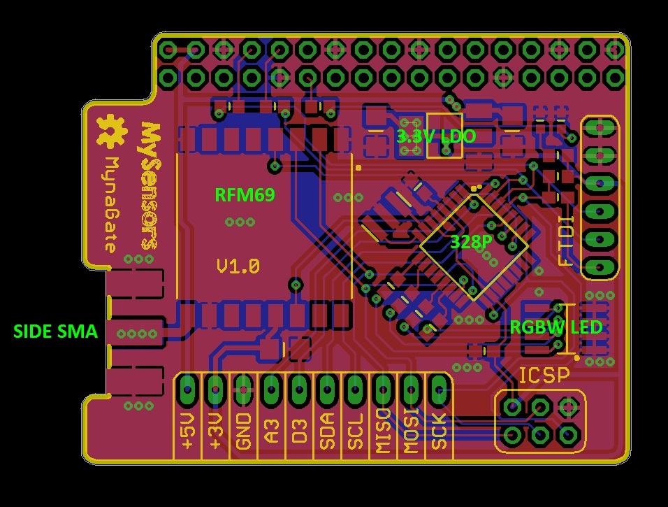
              The idea is to fit this and the raspberry in a normal enclosure. It should just need a hole for the SMA connector :

              rpigate.jpg

              Any advice for RPI cases ?

              Myna

              1 Reply Last reply
              0
              • mfalkviddM Offline
                mfalkviddM Offline
                mfalkvidd
                Mod
                wrote on last edited by
                #16

                The 3.3V output on the Raspberry Pi is rated for 50mA maximum current, which is plenty for the standard nrf24l01+ (specification says <15mA), but if you are using a radio with a power amp you might need more so the ldo could be a good idea.
                I am using this case because it has a hole for the gpio ports.

                1 Reply Last reply
                0
                • GertSandersG Offline
                  GertSandersG Offline
                  GertSanders
                  Hardware Contributor
                  wrote on last edited by
                  #17

                  @Myna Again a very nice board ! Since you made it in Eagle, you could just drop your .brd file on OSHPark and they will make it for you. I also dropped my latest 7.3.0 Eagle files there without a problem. Make sure you download the design rule file and check the board with it.
                  I made a DRU file which covers all limitations for OSHPark and DirtyPCB so that I can be sure that both can handle my designs.
                  Gert_Sanders.dru
                  Just rename it to whatever as long as it keeps the .dru extension and place it in the DRU directory of Eagle. I have used this DRU for two designs made by both PCB makers without a problem.
                  As for cases, I think most have a cutout for the camera ribbon, so you could enlarge that!
                  Here is the case I use:
                  IMG_7301.jpg
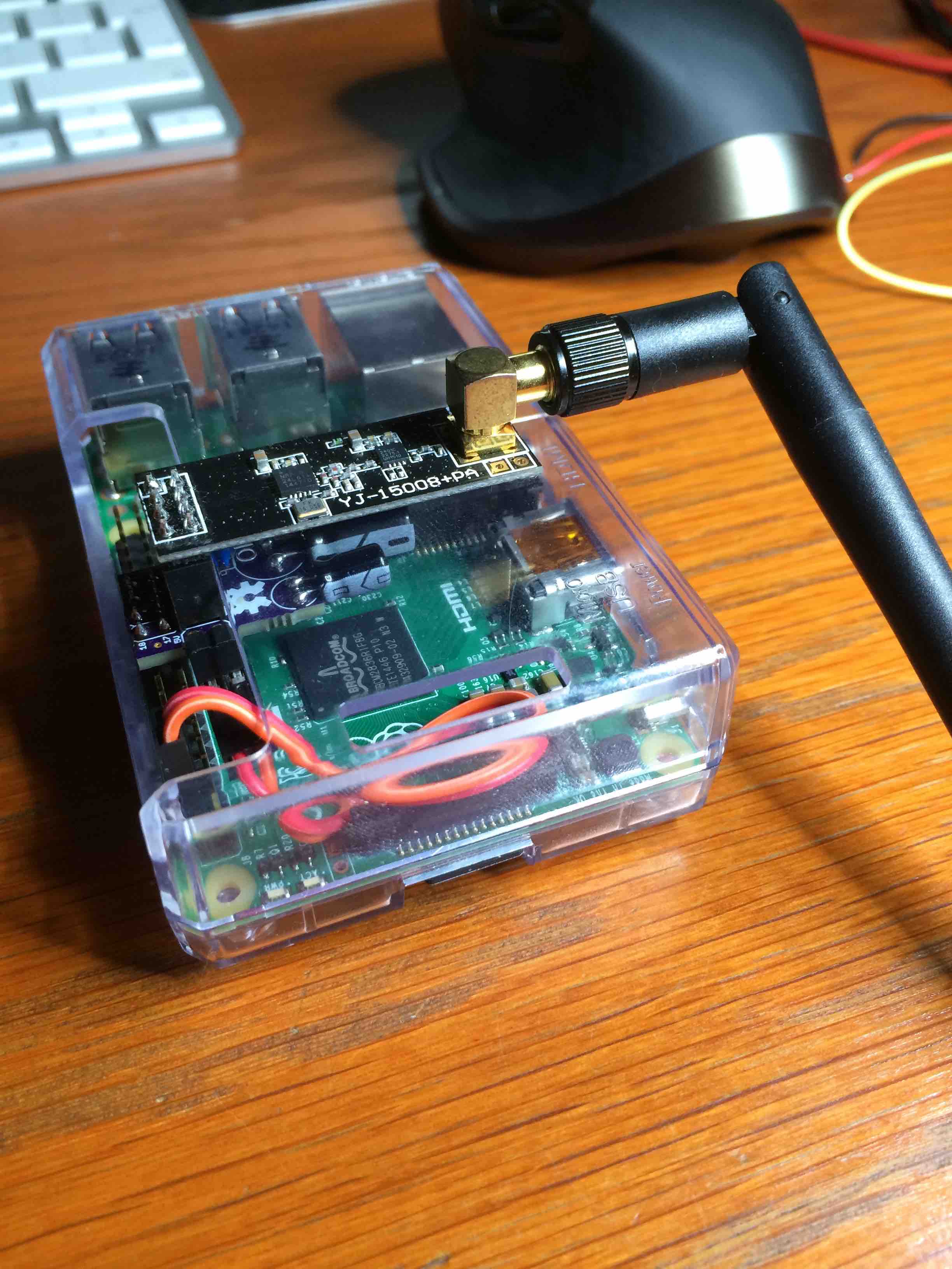
                  I got my case from here: https://www.antratek.com/raspberry-pi-model-b-enclosure-clear

                  1 Reply Last reply
                  0
                  • M Offline
                    M Offline
                    Myna
                    wrote on last edited by
                    #18

                    Thanks guys ! I think it will be itead studio as it seems they have the cheaper price for 5*10cm. I've checked the board with Seeed DRU.

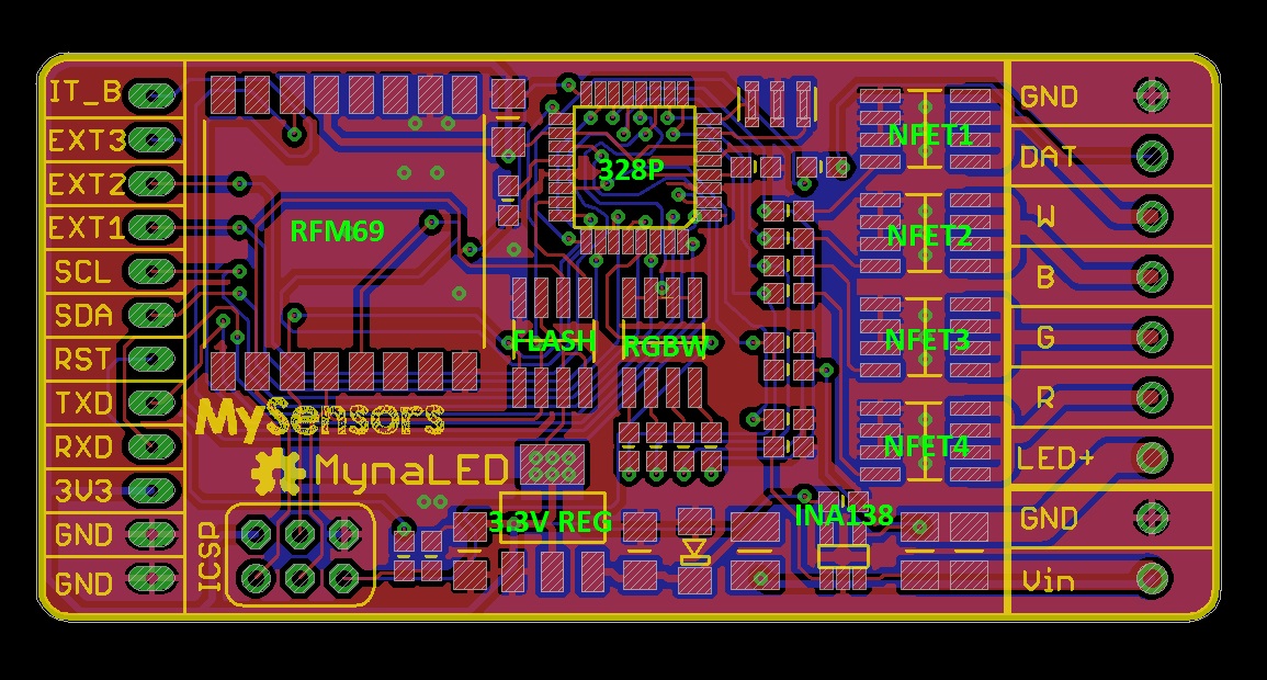
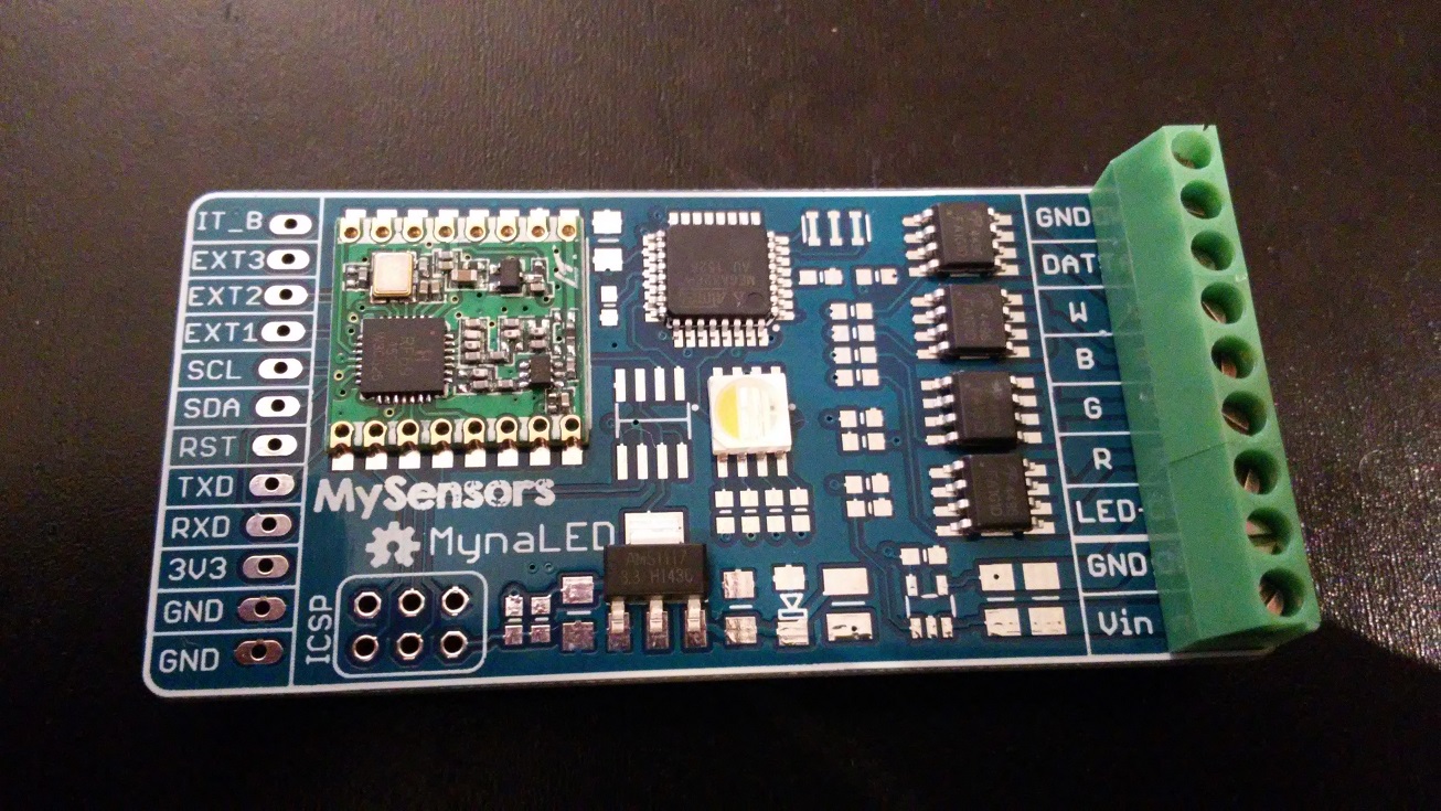
                    The last board : an RGBW and DC PWM dimmer. I'm really into lighting design, so that's very important for me.

                    **Specs: **

                    • 5 to 24V input. Work with 5, 12 or 24V led strip or power LEDs.
                    • should handle 3-4A per output with no problem. AO4496 Mosfets. (depend of PWM frequency)
                    • measure of the LEDs supply voltage ( resistor bridge to ADC)
                    • measure of the LEDs supply current (sense resistor, INA138 to ADC)
                    • DATA and GND header to drive intelligent LED strips (WS2812 , etc)
                    • Power and LEDs / LED Strip connection trough 3.5mm screw headers
                    • OTA hardware (spi flash), RGBW 5050 monitor LED, expansion ports as usual

                    mynaLEDV1.jpg

                    Now let's final check the board and make the order !

                    1 Reply Last reply
                    2
                    • J Offline
                      J Offline
                      jesper
                      wrote on last edited by
                      #19

                      It is interesting, what is the status ? ,
                      Have you have tested the 2AA Sensor Board + RPI Gateway and it works well.

                      1 Reply Last reply
                      0
                      • sundberg84S Offline
                        sundberg84S Offline
                        sundberg84
                        Hardware Contributor
                        wrote on last edited by
                        #20

                        Cool! Have you considered the MYSX connector?

                        Controller: Proxmox VM - Home Assistant
                        MySensors GW: Arduino Uno - W5100 Ethernet, Gw Shield Nrf24l01+ 2,4Ghz
                        MySensors GW: Arduino Uno - Gw Shield RFM69, 433mhz
                        RFLink GW - Arduino Mega + RFLink Shield, 433mhz

                        1 Reply Last reply
                        0
                        • M Myna

                          Hi everyone,

                          I was close to buy a Fibaro complete set until I discovered MySensors Project. This project is really cool, I'd like to thanks everyone involved in it. I'm more an hardware guy, so I wanted to do a little sensor board that I can spin for 10 units or something like that to cover the needs of my apartment.

                          I decided to design a little sensorboard that fit on the back of a 2AA holder ( 58*33mm) that can fit all the sensors I would need. The idea is that once you have the PCB, you solder just what you need on it. But it can work with every sensors populated also.

                          After days of reading and comparing sensors / supplies solutions, these are the specifications I choose:

                          • Works on two AA batteries in series. Use an MCP16252 to generate 3.3V that is enabled by default but can be switched off (and so bypassed) by the MCU if the batteries voltage is enough.
                          • Battery voltage monitored by the MCU
                          • Arduino compatible atmega328p design. External 512k spi flash for future OTA
                          • RFM69HCW design. It seems this is better for range and overall reliability ?
                          • PIR sensor: Custom design with the E931.96
                          • Light sensor: TSL2591
                          • Temp/Humidity sensor: Can use SI7020, HTU21D, and SHT2x range from sensirion
                          • Pressure sensor: BMP280
                          • IMU: MPU6050, MPU9255
                          • Two RGBW 5050 LEDs
                          • Extension connectors that can be used to stack extension board on top of the PCB.

                          I estimated it could achieve 1 to 3 years of battery life. I try to implement every hardware energy saving possibilities (hardware interrupts, ...).

                          Have you any advice or comments on this ? I have zero experience with MySensors and these sensors, so that could help. Here is a preview of the PCB : (routing still in progress). If anyone would like to see the schematics, I just need to clean it to release. This will be open source hardware if anyone is interested.

                          mysens1.jpg

                          Myna

                          F Offline
                          F Offline
                          freeck
                          wrote on last edited by freeck
                          #21

                          @Myna

                          Hi there,

                          Is there a driver available for the PIR E931.96 interface chip? There are sources available for an arm-processor, but for atmel328?
                          PIR-sensor LHI968 as used in an application note of Excelitas is available at aliexpress for aprox 2 Euro.

                          1 Reply Last reply
                          0
                          • M Offline
                            M Offline
                            Myna
                            wrote on last edited by
                            #22

                            Hi there !

                            I'm waiting for the boards and some components. Then I will be able to test, and write drivers (E931.96, no driver at the moment) and software for the system.

                            I'm cleaning my files / schematics to release everything.

                            I wasn't really aware of MYSX connector. After looking the PDF specs, It's not even clear how many pins it has, it look like every new versions add some pins ? It could be considered for a future version.

                            The thing is I have never worked on an home automation before, nor mysensors. So the idea here was to design a few board that are enough for my basic project needs (RGBW lighting, low voltage halogen lighting, multiple multisensor, Jeedom RPI controller). At the moment I don't really know what flavor of extensions I would one day like to add to the boards so I tried to breakout a maximum of pins, with clear silkscreen, even if it makes the boards bigger. I see this as a dev project to dive into mysensors. Future rev will probably follow if it works for me.

                            Myna

                            1 Reply Last reply
                            0
                            • M Offline
                              M Offline
                              Myna
                              wrote on last edited by
                              #23

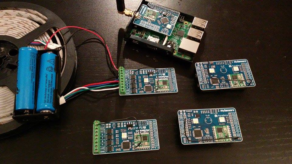
                              PCB and some components are are now arrived ! PCB are from Elecrow, I'm pretty satisfied with the result and silkscreen.

                              Hopefully I will be able to start some tests this weekend.

                              **2AA Multisensorboard: **
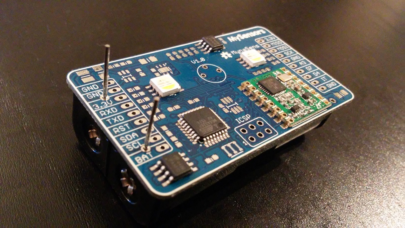
                              IMG_20151218_175039.jpg

                              **RGBW Dimmer board: **
                              IMG_20151218_174637.jpg

                              **Raspberry Pi Serial Node : (fit in this little plastic case) **
                              IMG_20151218_173920.jpg

                              Myna

                              1 Reply Last reply
                              3
                              • D Offline
                                D Offline
                                DavidZH
                                wrote on last edited by
                                #24

                                That looks promising! Is there any chance you'll release the files for others to use? I'm very interested in the dimmer module. And I'm glad there's more people using the RFM69. I thought I was a lone ranger in that respect.

                                M 1 Reply Last reply
                                0
                                • D DavidZH

                                  That looks promising! Is there any chance you'll release the files for others to use? I'm very interested in the dimmer module. And I'm glad there's more people using the RFM69. I thought I was a lone ranger in that respect.

                                  M Offline
                                  M Offline
                                  Myna
                                  wrote on last edited by
                                  #25

                                  @DavidZH Of course, this is an openharware project, everything will be released ! I can share the files in the current state but this is early dev state: I've already found two errors in the PCBs.

                                  After some soldering and fiddling with software I have the gateway talking to one sensorboard : I'm excited !

                                  1 Reply Last reply
                                  0
                                  • D Offline
                                    D Offline
                                    DavidZH
                                    wrote on last edited by
                                    #26

                                    Cool! This thread will be bookmarked!

                                    1 Reply Last reply
                                    0
                                    • M Offline
                                      M Offline
                                      Myna
                                      wrote on last edited by
                                      #27

                                      Testing the folowing hardware:

                                      12421748_10208518385382383_125320644_n.jpg

                                      12395298_10208518385462385_856753459_n.jpg

                                      It seems to work (basic hardware test). It still miss the DC/DC convefter and PIR sensor.

                                      However, I have a very strange problem with RFM69:

                                      gateway -> node rfm communication seems to have a very good range (Even with no antenna on the gateway, work everywhere in my appartment). But node -> gateway dont work past 30 ou 40cm. Tested with same 3.3V regulated supply. Any idea?

                                      Thanks!

                                      1 Reply Last reply
                                      0
                                      • alexsh1A Offline
                                        alexsh1A Offline
                                        alexsh1
                                        wrote on last edited by
                                        #28

                                        @Myna Hi, Any update on this project please?

                                        1 Reply Last reply
                                        0
                                        • C Offline
                                          C Offline
                                          chbla
                                          wrote on last edited by
                                          #29

                                          any update?

                                          1 Reply Last reply
                                          0
                                          Reply
                                          • Reply as topic
                                          Log in to reply
                                          • Oldest to Newest
                                          • Newest to Oldest
                                          • Most Votes


                                          12

                                          Online

                                          11.7k

                                          Users

                                          11.2k

                                          Topics

                                          113.0k

                                          Posts


                                          Copyright 2019 TBD   |   Forum Guidelines   |   Privacy Policy   |   Terms of Service
                                          • Login

                                          • Don't have an account? Register

                                          • Login or register to search.
                                          • First post
                                            Last post
                                          0
                                          • MySensors
                                          • OpenHardware.io
                                          • Categories
                                          • Recent
                                          • Tags
                                          • Popular