Easy/Newbie PCB for MySensors
-
Awesome board!!!
How do I access A2, A3 and D8?Thanks a lot
@hiddenuser - they are not accesses through the PCB:
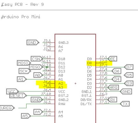
You need to solder a wire on the Pro Mini and run somewhere, like the prototyping area.
-
@hiddenuser - they are not accesses through the PCB:
You need to solder a wire on the Pro Mini and run somewhere, like the prototyping area.
@sundberg84 Thanks a lot.... My ebay seller sent me a Atmega168 5v. I have noticed that you boards supports 5v version too. Would I be able to power it using raw (12v).
Thanks a lot .
-
@sundberg84 Thanks a lot.... My ebay seller sent me a Atmega168 5v. I have noticed that you boards supports 5v version too. Would I be able to power it using raw (12v).
Thanks a lot .
@hiddenuser - as long as the voltage divider on the board supports 12v that will work. A warning on the cheap chinese stuff is that this voltage regulator is bad and might fry.
-
@hiddenuser - as long as the voltage divider on the board supports 12v that will work. A warning on the cheap chinese stuff is that this voltage regulator is bad and might fry.
-
@sundberg84 - thanks for your board, it seems to be almost exactly what I was looking for! What do you think would be the best way to adjust it if I need to boost the batteries not only to 3.3V, but also to 5V to run the pir sensor?
@achurak1 - do you mean running 5v on batteries? Sorry - thats out of my knowledge.
I guess there are 5v boosters but my guess is also that this will drain the batteries pretty fast.
I have made test with 9v batteries and voltage regulaters and this has worked for some time but never gives the lifetime as 3.3v on 2xAA. -
@achurak1 - do you mean running 5v on batteries? Sorry - thats out of my knowledge.
I guess there are 5v boosters but my guess is also that this will drain the batteries pretty fast.
I have made test with 9v batteries and voltage regulaters and this has worked for some time but never gives the lifetime as 3.3v on 2xAA.@sundberg84 - correct, the 5v booster looks exactly like the 3.3v booster. I have another sensor I've built manually and it works exactly like that, arduino/temp/hum/radio all work from 3.3v and pir works from 5v. I power it all with two rechargeable batteries (so ~2.6 max charged, not even 3) and it's been running good for several months already and still shows 2.45-2.50.
-
@sundberg84 - correct, the 5v booster looks exactly like the 3.3v booster. I have another sensor I've built manually and it works exactly like that, arduino/temp/hum/radio all work from 3.3v and pir works from 5v. I power it all with two rechargeable batteries (so ~2.6 max charged, not even 3) and it's been running good for several months already and still shows 2.45-2.50.
-
@achurak1 do you know you could modify the pir sensor to work directly from batteries by removing the regulator?
@gohan - I tried to connect the 3.3v to one of the three pins where you'd usually put a jumper (H, L pads) as I've seen people discussing it on this forum and it just didn't work for me, the sensor did work, but very unstable, would fire up every time radio sends or receives something.
-
Because you need to add an extra AA battery to increase voltage to around 4,5v just for the pir sensor
@gohan - not sure how exactly it answers my question? I thought you meant I could run the pir from 3.3v. I could plug everything to an outlet and don't worry about the batteries at all. The pir works perfectly from two batteries and the 5v booster, so why would I want to add more batteries and make the whole thing much bigger?
-
Im doing a new revision here with RFM69 support.
I never used the RFM69 though - is there anything I should take in mind?- Is it the same with IRQ as Nrf24l01+ - not used, but good to have ie. should i have a jumper so the user can connect IRQ ?
- The antenna, is it enough with a jumper/hole so the user can solder a antenna of their own? Or is the trace/trace-length also included as the antenna?
-
The problem with rfm69 is that they work on 3 different frequencies, so you have to choose which frequency you want to support. I'm not sure if the correct length for the 433mhz is good also for the 866mhz. Let's hope somebody more expert shows up 😀
-
The problem with rfm69 is that they work on 3 different frequencies, so you have to choose which frequency you want to support. I'm not sure if the correct length for the 433mhz is good also for the 866mhz. Let's hope somebody more expert shows up 😀
@gohan - You mean with the antenna? (But the footprint is the same?)
Well, if the trace isnt added to the lenght of the antenna and I add a through-hole the user can just add what kind of lenght they want? -
The trace adds up to the antenna lengths for what I have seen so far, so I'd say to play safe and leave a hole where to solder the wire antenna or even better if it's near the edge of the pcb you could design a place to mount a sma connector for a real antenna. What do you think?
-
The trace adds up to the antenna lengths for what I have seen so far, so I'd say to play safe and leave a hole where to solder the wire antenna or even better if it's near the edge of the pcb you could design a place to mount a sma connector for a real antenna. What do you think?
@gohan - the problem is then if you buy a antenna from ebay with the right length. Added to the PCB trace the length will not match. I have to make the antenna hole as close as possible to the module then.
-
by looking around at other PCBs with sma connectors, they are close to radio module, but still a few millimeters away so I'd say you should be ok
@gohan - notised that as well. I have asked scalz over PM about this, I saw he made alot of RFM projects.
-
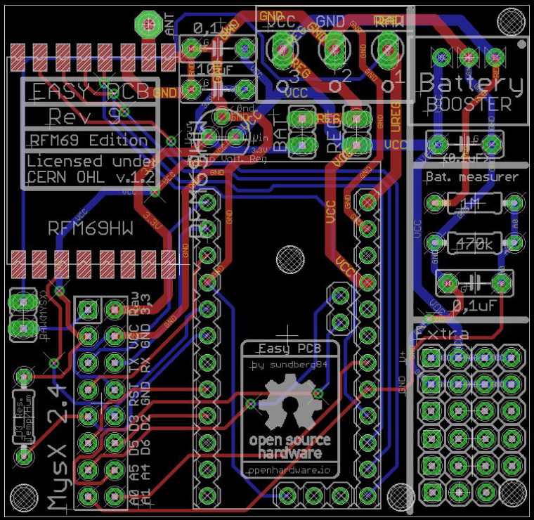
Sneak-peak at upcoming RFM edition.
All input appreciated as usual.- I couldnt fit a SMA connector at this point for external antenna because I dont want to remodel the PCB completley.
I want it to be as close looking to the original as possible to make it easier for newbies. - I went with the HW/W version. I talked to scalz and the CW is smaller and better for low power but HW/W is the one at MySensors website/tutorial/shop and preffered at 5v...
Thoughts?
- I couldnt fit a SMA connector at this point for external antenna because I dont want to remodel the PCB completley.