Skip to content
  • MySensors
  • OpenHardware.io
  • Categories
  • Recent
  • Tags
  • Popular
Skins
  • Light
  • Brite
  • Cerulean
  • Cosmo
  • Flatly
  • Journal
  • Litera
  • Lumen
  • Lux
  • Materia
  • Minty
  • Morph
  • Pulse
  • Sandstone
  • Simplex
  • Sketchy
  • Spacelab
  • United
  • Yeti
  • Zephyr
  • Dark
  • Cyborg
  • Darkly
  • Quartz
  • Slate
  • Solar
  • Superhero
  • Vapor

  • Default (No Skin)
  • No Skin
Collapse
Brand Logo
  1. Home
  2. Hardware
  3. Easy/Newbie PCB for MySensors

Easy/Newbie PCB for MySensors

Scheduled Pinned Locked Moved Hardware
257 Posts 37 Posters 105.3k Views 38 Watching
  • Oldest to Newest
  • Newest to Oldest
  • Most Votes
Reply
  • Reply as topic
Log in to reply
This topic has been deleted. Only users with topic management privileges can see it.
  • sundberg84S Offline
    sundberg84S Offline
    sundberg84
    Hardware Contributor
    wrote on last edited by sundberg84
    #24

    @shabba - I dont use RFM69 but if you order and debug i can build it.

    Controller: Proxmox VM - Home Assistant
    MySensors GW: Arduino Uno - W5100 Ethernet, Gw Shield Nrf24l01+ 2,4Ghz
    MySensors GW: Arduino Uno - Gw Shield RFM69, 433mhz
    RFLink GW - Arduino Mega + RFLink Shield, 433mhz

    1 Reply Last reply
    1
    • S Offline
      S Offline
      shabba
      wrote on last edited by
      #25

      I ordered some. Just would need a pin layout and make sure only 3.3v to all pins.

      1 Reply Last reply
      0
      • N Offline
        N Offline
        nunver
        wrote on last edited by
        #26

        @sundberg84 I am ordering the PCB's of Ver.8 today. Again, really nice and helpful work for newbies like me. Just one newbie question, though. I understand that both Arduino and NRF are capable of operating down to about 2V. Why do we need the booster in battery operation. I plan to use only Dallas 18B20. Thanks.

        1 Reply Last reply
        0
        • sundberg84S Offline
          sundberg84S Offline
          sundberg84
          Hardware Contributor
          wrote on last edited by
          #27

          @nunver Some sensors are not able to work down below 3.3v, and the im really skeptical if you can operate the arduino 3.3v down to 2v... mine dies when it reaches like 2.8V. Also, with a booster you can operate down to 0.9v - so i highly recommend it.

          Controller: Proxmox VM - Home Assistant
          MySensors GW: Arduino Uno - W5100 Ethernet, Gw Shield Nrf24l01+ 2,4Ghz
          MySensors GW: Arduino Uno - Gw Shield RFM69, 433mhz
          RFLink GW - Arduino Mega + RFLink Shield, 433mhz

          AnticimexA N 2 Replies Last reply
          0
          • sundberg84S sundberg84

            @nunver Some sensors are not able to work down below 3.3v, and the im really skeptical if you can operate the arduino 3.3v down to 2v... mine dies when it reaches like 2.8V. Also, with a booster you can operate down to 0.9v - so i highly recommend it.

            AnticimexA Offline
            AnticimexA Offline
            Anticimex
            Contest Winner
            wrote on last edited by
            #28

            @sundberg84 to get the arduino to operate at lower voltages you need to reconfigure a few fuses. Brown out reset and such things. I've seen the settings somewhere in the forum and a google search also works. There are online tools to set up the fuses (to get the values to write that is).

            Do you feel secure today? No? Start requiring some signatures and feel better tomorrow ;)

            1 Reply Last reply
            0
            • sundberg84S sundberg84

              @nunver Some sensors are not able to work down below 3.3v, and the im really skeptical if you can operate the arduino 3.3v down to 2v... mine dies when it reaches like 2.8V. Also, with a booster you can operate down to 0.9v - so i highly recommend it.

              N Offline
              N Offline
              nunver
              wrote on last edited by
              #29

              @sundberg84 thanks for clarification. From what @Anticimex wrote, I understand I have to tinker beyond my newbie hat :smile: to get Arduino to operate without booster. Thanks again.

              1 Reply Last reply
              0
              • sundberg84S Offline
                sundberg84S Offline
                sundberg84
                Hardware Contributor
                wrote on last edited by sundberg84
                #30

                @Anticimex Thank you for that input - i have not change the fuses.
                But a small warning to new members - its not kind of newbie friendly.

                Controller: Proxmox VM - Home Assistant
                MySensors GW: Arduino Uno - W5100 Ethernet, Gw Shield Nrf24l01+ 2,4Ghz
                MySensors GW: Arduino Uno - Gw Shield RFM69, 433mhz
                RFLink GW - Arduino Mega + RFLink Shield, 433mhz

                1 Reply Last reply
                0
                • BruseB Offline
                  BruseB Offline
                  Bruse
                  wrote on last edited by
                  #31
                  This post is deleted!
                  1 Reply Last reply
                  1
                  • D Offline
                    D Offline
                    dakipro
                    wrote on last edited by
                    #32

                    I just received first order and made one sensor, and I must say that I was a bit skeptical if this is the right pcb for me, I was thinking on somehow reducing footprint a bit or having a better idea about positioning of elements etc, but after making one node I realized that I LOVE IT! :)
                    It brings back the title of the build section of this website (Build = Fun), wheres before I would spend a whole afternoon (and usually have a headache in the evening) for just connecting the radio on the prototype board. Now I made a node with 4 nodes in ~1 hour, and it looks much better then the wire mess from before (old node on the right)
                    0_1458746186389_IMG_6040_1024.jpg

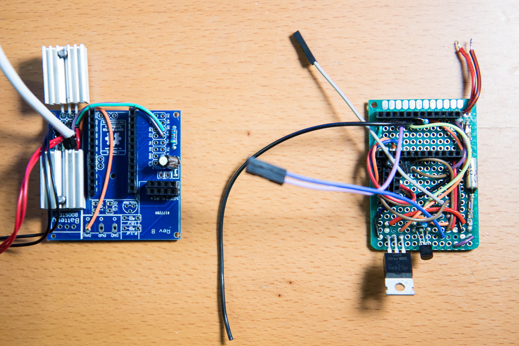
                    However I did spent about 3 hours debugging why my "touch" capacitive sensor doesn't work when I plug inn the radio (it works fine without the radio, which was just headbanging to figure out).

                    I have found that pin 2 is connected to the radio, which could be a good thing if mysensors begins to use IRQ pin on the radio. This probably works in 99% of the cases as it is today, but for the capacitive touch sensor when resistor is connected between pins 2 and four, node never detects that you are touching it. Scalpel blade solved this pretty easily, but it took me 4 hours to figure out what was going on and why my touch sensor doesn't work.

                    I would suggest then to either make pin 2 reserved to the radio, thus removing it from the "available pins" area, or disconnect it from the radio for the time being (not sure when it is planned to use IRQ pin). Or at least marking it somehow on the board if possible, so that we get reminded that pin2 is connected to the radio as well and could interfere with some sensors.

                    While on the subject of suggestions, I see there is almost no connections bellow the radio, so maybe radio could go a bit lower in the board so that it doesn't stick (having no metal parts/lines bellow the radio should not obstruct the signal, it is just empty pcb?) Preserving space for antenna could be done something like this https://www.openhardware.io/uploads/56ecf010b2b0966107ebedfa/image/1458410585539-image.jpeg . I am not sure when I will have some time (and energy) to learn to modify pcb files my self, but maybe it is easy for someone to try it :)

                    Otherwise, as said before, excellent work, this should be featured in the 'build' section of the website as it is one of the most useful things, especially for novices.

                    Thank you for making it

                    C: OpenHAB2 with node-red on linux laptop
                    GW: Arduino Nano - W5100 Ethernet, Nrf24l01+ 2,4Ghz mqtt
                    GW: Arduino Mega, RFLink 433Mhz

                    1 Reply Last reply
                    0
                    • sundberg84S Offline
                      sundberg84S Offline
                      sundberg84
                      Hardware Contributor
                      wrote on last edited by
                      #33

                      Hi @dakipro! Thank you for those kind words and thank you for the feedback.

                      About the IRQ pin, I will consider that, maybe a jumper, but what i know of the radio should not use this at all. Im not sure why its not working but good you found out. Do you use D3 for other things - if not i recommend to always use d3 instead of d2/irq.

                      Yes, in 99% if the cases you should be able to have the radio over the board... BUT I have had issue and since it should be a newbie frendly board i want it to work 100% of the times.

                      Controller: Proxmox VM - Home Assistant
                      MySensors GW: Arduino Uno - W5100 Ethernet, Gw Shield Nrf24l01+ 2,4Ghz
                      MySensors GW: Arduino Uno - Gw Shield RFM69, 433mhz
                      RFLink GW - Arduino Mega + RFLink Shield, 433mhz

                      1 Reply Last reply
                      0
                      • D Offline
                        D Offline
                        dakipro
                        wrote on last edited by
                        #34

                        I used d3 for dallas temp sensor but have already soldered d2 to touch sensor. Touch sensor is very unique as it is measuring resistance (actually i think it is measuring time) between to pins, and when you connect 1Mohm resistor between d4 and d2, then radio introduces some other resistance or something, and that messes up the readings for touch. We can use other pins, but pins 2 and 4 are set by default, and it never occurred to me that it is the radio-pin ting.

                        I have quite a few sleeping sensors where PIR is connected to d2 and door-magnet-sensor is connected to d3 for example, as those are (if I understood it right) pins that can wake up the node from sleeping. Maybe radio can interfere with some of those "common" sensors usually connected to the wake-up pins?

                        I would then vote for having d2 available in the "available pins" area because it is one of two wakeup pins, and maybe as you suggested have a jumper (or a disconnected line, that can be just shorted with a short wire) that goes to irq.

                        Anyway, I think it is not an issue-critical as a knife solves it quickly, but it could demoralize us newbies :)

                        C: OpenHAB2 with node-red on linux laptop
                        GW: Arduino Nano - W5100 Ethernet, Nrf24l01+ 2,4Ghz mqtt
                        GW: Arduino Mega, RFLink 433Mhz

                        1 Reply Last reply
                        1
                        • D Offline
                          D Offline
                          dakipro
                          wrote on last edited by dakipro
                          #35

                          I just got notification from Paypal that my donation was returned due to non-acceptance. I never experienced someone not willing to take donations via donate button :)
                          I used the donations link on the right box here
                          https://www.openhardware.io/view/4/EasyNewbie-PCB-for-MySensors

                          If it is due to technical reasons that is ok, but maybe you want to check the link or paypal notifications or something if you want to receive donations

                          C: OpenHAB2 with node-red on linux laptop
                          GW: Arduino Nano - W5100 Ethernet, Nrf24l01+ 2,4Ghz mqtt
                          GW: Arduino Mega, RFLink 433Mhz

                          1 Reply Last reply
                          1
                          • sundberg84S Offline
                            sundberg84S Offline
                            sundberg84
                            Hardware Contributor
                            wrote on last edited by sundberg84
                            #36

                            Hi dakipro! Aaah that was you :) sorry.
                            I wasnt notified (or missed in spam?) I got a donation until i got an email this morning saying it was returned. During this time i had not visited paypal and I had not idea I had to accept.

                            Controller: Proxmox VM - Home Assistant
                            MySensors GW: Arduino Uno - W5100 Ethernet, Gw Shield Nrf24l01+ 2,4Ghz
                            MySensors GW: Arduino Uno - Gw Shield RFM69, 433mhz
                            RFLink GW - Arduino Mega + RFLink Shield, 433mhz

                            1 Reply Last reply
                            0
                            • N Offline
                              N Offline
                              nunver
                              wrote on last edited by
                              #37

                              @sundberg84 Just received the boards and installed my first node with it. I wanted to test all voltages are correct before hooking up the Arduino and NRF. Noticed that I get battery voltage at NRF and booster voltage on Arduino. Checked the schematic. It the board I received is correct after all. Is this intentional that we do not use booster voltage for NRF?

                              THanks

                              1 Reply Last reply
                              0
                              • sundberg84S Offline
                                sundberg84S Offline
                                sundberg84
                                Hardware Contributor
                                wrote on last edited by
                                #38

                                Hi @nunver - Yes that is correct, Search the forum - it has been proven much better.
                                Nrf can handle down to 0.9v so its not a problem.

                                Controller: Proxmox VM - Home Assistant
                                MySensors GW: Arduino Uno - W5100 Ethernet, Gw Shield Nrf24l01+ 2,4Ghz
                                MySensors GW: Arduino Uno - Gw Shield RFM69, 433mhz
                                RFLink GW - Arduino Mega + RFLink Shield, 433mhz

                                1 Reply Last reply
                                0
                                • barduinoB Offline
                                  barduinoB Offline
                                  barduino
                                  wrote on last edited by
                                  #39

                                  Hi folks,

                                  I finally had some time to assemble a couple of boards and they work perfectly.

                                  0_1460304197463_IMG_0451.JPG

                                  0_1460304220163_IMG_0452.JPG

                                  2 things I need to do though and I appreciate any feed back folks may have.

                                  Connect the voltage divider in a more elegant way, perhaps directly from the raw, however I wanted to keep the options open just in case some of the boards end up using REG or BAT.

                                  Find a way to protect the VIN input against accidental reverse polarity. I ended up frying the voltage regulator on the arduino when I accidental touched the 9v battery on its connector reversed. Its quite a show with glowing red and sparks flying (the arduino actually survived but no more raw power).

                                  @sundberg84 once again thanks for this board!!!

                                  Cheers

                                  sundberg84S 1 Reply Last reply
                                  0
                                  • barduinoB barduino

                                    Hi folks,

                                    I finally had some time to assemble a couple of boards and they work perfectly.

                                    0_1460304197463_IMG_0451.JPG

                                    0_1460304220163_IMG_0452.JPG

                                    2 things I need to do though and I appreciate any feed back folks may have.

                                    Connect the voltage divider in a more elegant way, perhaps directly from the raw, however I wanted to keep the options open just in case some of the boards end up using REG or BAT.

                                    Find a way to protect the VIN input against accidental reverse polarity. I ended up frying the voltage regulator on the arduino when I accidental touched the 9v battery on its connector reversed. Its quite a show with glowing red and sparks flying (the arduino actually survived but no more raw power).

                                    @sundberg84 once again thanks for this board!!!

                                    Cheers

                                    sundberg84S Offline
                                    sundberg84S Offline
                                    sundberg84
                                    Hardware Contributor
                                    wrote on last edited by
                                    #40

                                    @barduino - thank you for great feedback!
                                    I will look into whats possible if i have any upcoming revs.

                                    Controller: Proxmox VM - Home Assistant
                                    MySensors GW: Arduino Uno - W5100 Ethernet, Gw Shield Nrf24l01+ 2,4Ghz
                                    MySensors GW: Arduino Uno - Gw Shield RFM69, 433mhz
                                    RFLink GW - Arduino Mega + RFLink Shield, 433mhz

                                    barduinoB 1 Reply Last reply
                                    0
                                    • sundberg84S sundberg84

                                      @barduino - thank you for great feedback!
                                      I will look into whats possible if i have any upcoming revs.

                                      barduinoB Offline
                                      barduinoB Offline
                                      barduino
                                      wrote on last edited by
                                      #41

                                      @sundberg84 , I forgot to mention something.

                                      I get my pro mini's from the local mega store and they have their own brand at a very good price.

                                      In the model they sell the A6, A7 and Ground do not line up with the board.

                                      Not a problem for my applications (I'm thinking of soldering some angled connectors) but I was wondering if they are supposed to be in that position from the original specs.

                                      If you ever think of making the board a bit bigger, having 4 extra connectors for A6, A7, D8 (and an extra ground perhaps) would be nice.

                                      Great job on these!!!

                                      Cheers

                                      0_1460343220919_IMG_0456.JPG

                                      1 Reply Last reply
                                      0
                                      • N Offline
                                        N Offline
                                        nunver
                                        wrote on last edited by
                                        #42

                                        @barduino nice board. One question, why do you have the cable? Sorry for my newbie question :blush:

                                        barduinoB 1 Reply Last reply
                                        0
                                        • N nunver

                                          @barduino nice board. One question, why do you have the cable? Sorry for my newbie question :blush:

                                          barduinoB Offline
                                          barduinoB Offline
                                          barduino
                                          wrote on last edited by
                                          #43

                                          @nunver, it's not my board, @sundberg84 design it and made it available for all of us.

                                          The wire you see is to connect the RAW input to the voltage divider so I can measure the 9v battery.

                                          Cheers

                                          N 1 Reply Last reply
                                          0
                                          Reply
                                          • Reply as topic
                                          Log in to reply
                                          • Oldest to Newest
                                          • Newest to Oldest
                                          • Most Votes


                                          17

                                          Online

                                          11.7k

                                          Users

                                          11.2k

                                          Topics

                                          113.1k

                                          Posts


                                          Copyright 2025 TBD   |   Forum Guidelines   |   Privacy Policy   |   Terms of Service
                                          • Login

                                          • Don't have an account? Register

                                          • Login or register to search.
                                          • First post
                                            Last post
                                          0
                                          • MySensors
                                          • OpenHardware.io
                                          • Categories
                                          • Recent
                                          • Tags
                                          • Popular