Easy/Newbie PCB for MySensors


  • Hardware Contributor

    Hi dakipro! Aaah that was you 🙂 sorry.
    I wasnt notified (or missed in spam?) I got a donation until i got an email this morning saying it was returned. During this time i had not visited paypal and I had not idea I had to accept.


  • @sundberg84 Just received the boards and installed my first node with it. I wanted to test all voltages are correct before hooking up the Arduino and NRF. Noticed that I get battery voltage at NRF and booster voltage on Arduino. Checked the schematic. It the board I received is correct after all. Is this intentional that we do not use booster voltage for NRF?

    THanks


  • Hardware Contributor

    Hi @nunver - Yes that is correct, Search the forum - it has been proven much better.
    Nrf can handle down to 0.9v so its not a problem.


  • Hi folks,

    I finally had some time to assemble a couple of boards and they work perfectly.

    0_1460304197463_IMG_0451.JPG

    0_1460304220163_IMG_0452.JPG

    2 things I need to do though and I appreciate any feed back folks may have.

    Connect the voltage divider in a more elegant way, perhaps directly from the raw, however I wanted to keep the options open just in case some of the boards end up using REG or BAT.

    Find a way to protect the VIN input against accidental reverse polarity. I ended up frying the voltage regulator on the arduino when I accidental touched the 9v battery on its connector reversed. Its quite a show with glowing red and sparks flying (the arduino actually survived but no more raw power).

    @sundberg84 once again thanks for this board!!!

    Cheers


  • Hardware Contributor

    @barduino - thank you for great feedback!
    I will look into whats possible if i have any upcoming revs.


  • @sundberg84 , I forgot to mention something.

    I get my pro mini's from the local mega store and they have their own brand at a very good price.

    In the model they sell the A6, A7 and Ground do not line up with the board.

    Not a problem for my applications (I'm thinking of soldering some angled connectors) but I was wondering if they are supposed to be in that position from the original specs.

    If you ever think of making the board a bit bigger, having 4 extra connectors for A6, A7, D8 (and an extra ground perhaps) would be nice.

    Great job on these!!!

    Cheers

    0_1460343220919_IMG_0456.JPG


  • @barduino nice board. One question, why do you have the cable? Sorry for my newbie question 😊


  • @nunver, it's not my board, @sundberg84 design it and made it available for all of us.

    The wire you see is to connect the RAW input to the voltage divider so I can measure the 9v battery.

    Cheers


  • @barduino yes I know the boards are designed by sundberg84. I got my boards manufactured as well. What I meant was nicely done.

    As for the cable, you could have got raw voltage from the battery booster pin. I was wondering if for any specific reason you had the cable. I understand not.

    Regarding protection against reverse polarity, can't you use a diode? You loose 0.6V but there is ample margin.


  • @nunver your're right I need a more elegant solution for that wire, there was no particular reason to connect it on the other side.

    For the protection i'm thinking a daughter board with the diode and the 9v connector and then join it with angle connectors on the main.

    Cheers


  • Hardware Contributor

    @barduino ok - strange with that footprint.
    According to Arduino website those holes does not exist in that position at all (either as your board or my PCB are designed). I downloaded a popular pro mini footprint from somewhere and used that - first time i see they are not aligned.


  • yes, indeed

    alt text

    source: https://www.arduino-board.com/boards/arduino-pro-mini

    anyway, no worries, I was just curious

    Cheers


  • @sundberg84 Assembled my second node. This time 5V regulated. One remark and a quick question. You have LE33 in BOM as regulator. I did not have one readily available but an LM1117 which is a totally different package. I had to go through all datasheets to get correct pinout. Could you put labels near pins like 5 3 G?

    And the question; dumb as it may sound, do we place a jumper at REG pins when using the regulator version? 😕


  • Hardware Contributor

    @nunver - great idea with the labels for voltage reg - that makes it more userfriendly! Will do.
    Yes - REG should have a jumper connected.


  • What is the purpose of the Raw connection under the radio connection? Designed for a jumper to supply RAW to MYSX connection?
    Also any other caveats to be aware of when using RAW and a 3.3 mini and skipping the regulator?


  • Hardware Contributor

    @shabba - Its a criteria of the MysX connector - to be able to switch RAW on/off from a daughter pcb. Nothing I have ever used and you dont have to think about it until you have a mother/daughter board.

    Using RAW input and the internal regulator on the arduino you need to bypass the "REG" jumper and also the external voltage regulator if i remember right.


  • @sundberg84
    Hey, I've been having a bit of trouble lately.
    I've been trying to setup a node with your board which supports a PIR and a temp sensor (ds18b20).
    Since there is a spot for a resistor on D3 on your board, I attached the temp sensor to that pin.
    The PIR needs a pin that supports interrupts, so I connected that to D2.
    Here is where the confusion starts.
    If I read this page correctly, D2 is already in use for the radio.
    I only checked it after I soldered everything together and found out my PIR doesn't work (it always sends a 1-signal).

    Any thoughts on this?
    Is D2 really free for use on the board?

    Thanks!


  • Hardware Contributor

    @BastienVH - D2 is connected, but at this point not used by the radio (unless its been changed very recently). On the PCB its connected though - so if you want to use this I suggest you do not solder that pin (ie disconnect it) from the PCB and try.

    If your PIR doesnt work you should start there... the cheap PIRS are very power sensitive (feed 5v not 3.3!! (you can modify this but standard is 5v!)) so check the connection with a multimeter. Try to connect only PIR and run a basic sketch to get that one to work. As you said you need to connect them to 2 or 3 if you want to use interrupt.

    Add some serial.println to get info out whats happeing with the PIR.


  • @sundberg84
    About D2: you mean I shouldn't solder the IRQ of the radio to the board?
    I will try that next time.

    I've been testing the PIR with a nano and the 3.3V it supplies and that works fine.
    If I take VCC or ground (or both) from the board with booster, the PIR starts acting up.
    I guess I'll have to try some more if I want to get to the bottom of things.


  • Hardware Contributor

    @BastienVH I have tried the normal china-pir (HC-SR501) on 3.3v and it does not work very well. I got random on/off or just strange behaivour. See specs! Voltage is 5V – 20V if you dont modify it (there are some threads on the forum).

    The easiest way is to remove the pin for D2 on the arduino pinhead.


  • @sundberg84 Any idea why I've received a "2nd version" of your Rev.8 from PCBWay for free? By free I mean that I bought 10x your Rev.8 about 2 months ago (Black in the photo), but today I've got a package from China and when I opened I got that other PCB that I haven't ordered 😕
    I don't see any changes regarding the radio capacitor. Any clue? 0_1465478705931_IMG_6741.jpg


  • Hardware Contributor

    @danivalencia - sorry for late reply, I think @hek can help you. Give him a chat about this.


  • @sundberg84 No worry, I talked with hek and he finded that was a pcbway mistake. BTW...very good job with the PCB, I'm using it with a lot of my sensors 😉


  • Hi there !

    @sundberg84 very nice job ! 🙂
    is there any plan to fit the board for the Arduino Nano (5V) ?


  • Hardware Contributor

    @Lior-Rubin - Not at this point.
    What would be the benefits compared to Pro Mini?
    Nano can only handle 5v input and not 3.3.


  • @sundberg84 Nothing special behalf of the face that it easier to program it (it has mini USB onboard).


  • Hardware Contributor

    @Lior-Rubin Yes - you are right, the Nano is easier.
    But I want to stick with the pro mini and the advantages with both a 3.3 and a 5v version for both battery operations and regulated power. You are free if you like to modify my design to your wish and add a Nano instead. If you need any help just ask!


  • @sundberg84 Thanks, I'll try to play with the Pro Mini 🙂
    BTW - can you recommend for good supplier from eBay\AliExpress\Etc. ?


  • Hardware Contributor

    @Lior-Rubin - For components i pretty much use the links from www.mysensors.com/store
    Dont forget to order a fdti programmer 🙂


  • @sundberg84 I have all these ... I meant for the Pro Mini 3.3V that you used in your design.
    I ordered some from Chinese supplier but the board was damaged ( cannot upload sketches to them).

    where did you get yours ?


  • Hardware Contributor

    @Lior-Rubin - 3 batches from china, link in mysensor store - worked great for me.


  • Hi, I have received the PCBs, it is good help.
    (3.3v mini with battery powering)
    I have wiring problem. How could I connect radio's power input to boosted powering source to get stable 3.3v?
    thanks


  • Mod

    @Barna see the instructions for "Regulated 5V" and "6-12v to RAW pin" on https://goo.gl/1ZMlUf https://www.openhardware.io/view/4/EasyNewbie-PCB-for-MySensors


  • Hardware Contributor

    @Barna Exaclty as @mfalkvidd said - use regulated power instructions instead.
    Set the jumper on "reg" and bypass the voltage converter with a wire.

    Whats good to know is that this has been tested over and over in this forum and the conclusion has been so far that if you run with 2xAA the best sollution is to bypass the radio in the booster (i.e. use battery instructions - hence the difference). The radio can handle down to 1.9v so it wont die for a long time if you have some power savings in use.


  • @sundberg84 yes, I would like to use 2xAA. I have measured it, 2xAA's out is 2.6V, after booster it is 3.3 .
    My first tying was battery jumper, but I had was radio problems.
    After bypassed the volt reg part to give 3.3v.
    When you have mentioned this : "Set the jumper on "reg" and bypass the voltage converter with a wire." do you talk about the jumper which next to battery jumper or the 2nd? I have tried which is next to radio.
    I have a filling, it will be soldering or hw issue, because both has worked, and has not sometimes.
    thanks


  • Hardware Contributor

    @barna - what was the radio problem? If it was range issues i have figured out that some boosters are bad quality but it helps to have a 0,1uF capacitor between out and gnd on the booster.

    Note that you can not use both REG and BAT function at the same time.

    I mean this:
    0_1467188130411_Skärmklipp.JPG
    but if you only have 2.6v im not sure the arduino is going to function properly. With this setup the booster is not active and 2.6v is fed into all components. this is meant for 5v.

    As i said - i recommend using the bat and booster setup and instead try to figure out the radio problem.


  • @sundberg84 I'm using battery with booster


  • Hardware Contributor

    Then connect it like battery and booster (BAT jumper) and try to figure out why you have the radio problems. Thats my advice. The above is possible (REG) but as i said, i dont think it will work when the battery goes below 2.6v.


  • @sundberg84
    1.
    with battery jumper the radio will get direct 2.6v and work until 1.9v
    arduino will get 3.3v via booster
    2.
    If I bypass the REG all of them will get 2.6v
    Is my thinking right ?


  • Hardware Contributor

    @Barna - Exactly!
    So again - go with 1. if you are using 2xAA since the arduino needs 2.6-2.8v to funciton.


  • @sundberg84
    why is it problem technically, if I give boosted 3.3 to radio ?


  • Hardware Contributor

    @Barna - the Radio is very sensitive to spikes and disturbance in power. The booster generates more disturbance than the batteries. Thats why we came to the conclution that Bat -> radio is the best choise. If not, you can remove some disturbance with a capacitor as I wrote above with 0.1uF from out to ground on the booster.

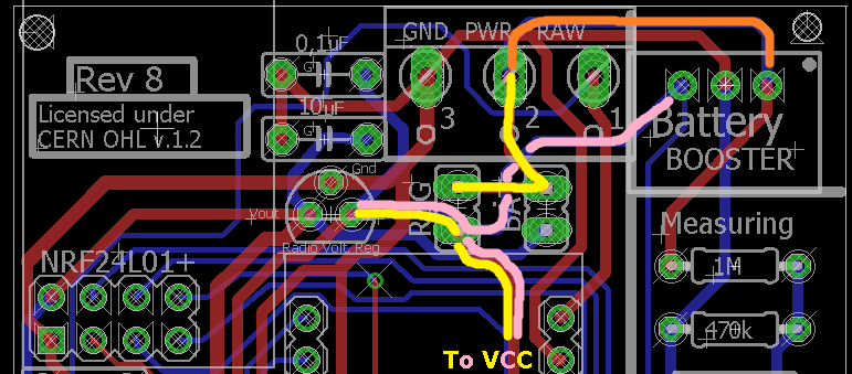
    The PCB is designed in either Bat or Reg and its not optimal using battery power, booster and a jumper on reg. You will get two voltages (bat + 3.3booster to radio):
    0_1467205844941_1.png

    You can try different setups - report back 🙂 but i can only recommend the modes described in the openhardware.io


  • Hi sundberg84,
    Is it possible to use 5v mini + 9v battery with measurement ?
    I put an voltage regulator to booster place and power the radio from mini with 5-3.3 regulator ?
    What do you think ?

    I think I could use the 9V as source as raw, but it could be problematic because it is an battery, so I would like to measue it.

    thanks
    Barna


  • Hardware Contributor

    @Barna - Powering it through RAW is possible but if you want to use the booster and battery measuring this is not an option , you need to power it through PWR and BAT jumper. I think what you describe is possible but untested. First you need to find/create a booster that can handle the battery. Also you need to make corrections on the voltage divider(47k and 67k?) for the battery measuring and also code changes.

    Please share your results - this is good if this works!
    I was about to create one of these myself the other day - but other projects came by so i just skipped it and running a 3.3v (removed led) on 9v trough raw and it works... no measuring though so no clue how long it will last.


  • I'm not profi, is my logic correct?
    general, not PBC related
    I could power the mini 5V with 9V and mini's regulator converts it to 5V.
    Mini could give power to radio by 5->3.3 regulator.
    I could measure the voltage without booster, but the booster is good to use the battery until it is possible ?


  • Hardware Contributor

    @Barna Your logic is correct - you can power a mini through raw and the minis regulator will convert it to 5v but then you can not use the booster. You will have power as long as the battery is between aprox. 6 and 9 v (minis voltage converter specs), below that it will die.


  • I have ordered some boards and i am looking forward to play with them.
    I tried soldering some part and a nano on a soldering board but apparently my soldering skills and patience isn't what it used to be in the past.
    @sundberg84 it looks good.


  • Hardware Contributor

    @tlpeter thank you and good luck. Just give a shout if you have questions.


  • I do have some questions 😃

    I think i got it a bit. When i use a 3,3V mini then i do not need the 3,3V regulator and it is powered with a battery. If i use a 5V mini then i need the regulator. Is this correct?

    Do i need the booster if batteries are used?

    How about the RAW option? How does it go to 5V? i need the regulator to go to 3,3V so how do i loose the 6-12V 😃


  • Hardware Contributor

    @tlpeter said:

    When i use a 3,3V mini then i do not need the 3,3V regulator and it is powered with a battery. If i use a 5V mini then i need the regulator. Is this correct?

    Correct!! You need to add the jumper to BAT if you go with 3.3 and battery or REG if you go with 5v and voltage regulator.

    Do i need the booster if batteries are used?

    No, you can bypass it with a jumper/wire - but it will give you alot of extra. Without the booster the arduino 3.3v will die somewhere between 2.8 and 3 volts, with booster you can go down to 1.9v.

    How about the RAW option? How does it go to 5V? i need the regulator to go to 3,3V so how do i loose the 6-12V 😃

    There is a voltage regulater on board the pro mini that handels from 6-12v (be cautious using 12 v, 9v is max i recommend on clones). This will convert your RAW to 5v and provide the board with this. Then the external regulator will go from 5 to radio 3.3v.


  • Ok, very clear.
    So now i have a new question, i want to use a solar panel and a battery but this will go above the 3.7V when there is light and the battery pack is 3.7V so i must use the raw connection.
    I also want to measure the battery and i think this needs PWR 😃

    Can i do this?

    I want to build the solar powered mini weather station:

    https://forum.mysensors.org/topic/841/solar-powered-mini-weather-station

    Thanks already.


  • Hardware Contributor

    @tlpeter You can use raw for 3.7V and make it down to 3.3 with the internal voltage regulator onboard the arduino, but you can not connect anything to PWR then because this will allready be 3.3V! The internal voltage regulator vill output 3.3v to the PCB from the arduino.

    However, I think you can connect the battery directly to the battery measurment on the board as long as you use the same ground for both. You will need to make some new calculations (most are based on 2xAA = 3.0V) for your battery.


  • I didn't use your board in this case (the weather station) but i will do in the future.
    I did connect the battery to the raw pin and it is working fine.
    Funny, a solar panel with a battery powering the pro mini with DHT22 and BMP180.
    For now i will keep it simple but later on i want a rain gauge and windmeter too.
    Rain sensor is on a different Nano as this needs to be powered all the time.
    It will control my sunscreen later on.


  • This board looks great! Definitely going to order some.

    Just getting started with MySensors. Waiting for over 20 orders from eBay with stuff. Should be fun!
    Already running Domoticz (Pi 2) with RFXtrx433, 1-wire and z-wave. Going to build a serial gateway for direct connection to the Pi.

    My last name before I married (now divorced) was Sundberg btw. Could have had Sundberg82 as nickname. 😉


  • Hardware Contributor

    @NiklasO - Thanks! I hope it will suite you well!
    The wait is a pain, but well worth it in the end. Sounds like got alof going already!

    Hehe, we can create a forum group - "sundberg dreamteam!" 😉


  • Recived my boards today and I love them, I ordered the white ones and they are looking really great

    Thanks @sundberg84 !


  • Hardware Contributor

    @Martin-Tellblom - good luck with your projects!


  • @sundberg84 said:

    @NiklasO - Thanks! I hope it will suite you well!
    The wait is a pain, but well worth it in the end. Sounds like got alof going already!

    Hehe, we can create a forum group - "sundberg dreamteam!" 😉

    hehe yeah, just need to change my last name back to my original one but I don't know if my kids likes that idea. 😉

    Where do you get your x to 3.3v boost converter? Found some on eBay but they are quite expensive if comparing to x to 5v versions.


  • Hardware Contributor

    @NiklasO - they are quite expencive yes, but i order the ones in the mysensors store


  • Has anyone tried one of these boosters:

    https://www.aliexpress.com/item/High-current-2A-DC-DC-SX1308-adjustable-boost-module/32751065114.html?ws_ab_test=searchweb0_0,searchweb201602_1_116_10065_117_10068_114_10067_115_10069_113_10017_10080_10082_10081_10060_10061_10062_10056_10055_10037_10054_10033_10059_10032_10078_10079_10077_10073_10070_421_420_10052_10053_10050_10051,searchweb201603_7&btsid=c5657706-88c2-41fb-bdfe-866e4cffe76a

    • They are sometimes much cheaper than the 3.3v ones
    • Since they are adjustable, I would think you could optimize the output voltage for maximum battery.

    I'm not sure, is there a problem using them with the PCB boards? I imagine the input and output ground would have to be connected together.

    Thanks!


  • Hardware Contributor

    @ileneken3 - sorry never tried them.
    The footprint looks different from the PCB so you need to connect this with wires to the PCB.


  • @sundberg84

    I took a chance and tried these boosters. After adjusting the pot to boost to 3.3V, and using wires to connect, they seem to work the same as the "recommended" ones. I am hoping they produce less noise for the radio - I seem to have trouble with that, even with adding the capacitors. (Maybe my radios are not good).
    Another experiment - boosting them to just over the 2.8V fuse limit. I would think that would be more energy efficient.


  • @ileneken3 in my experienxe the 3.3v booster gives a lot of problem with radio 🙂


  • Hardware Contributor

    @jumping - correct, if you can make a node without its better for the radio but its easier to do with a booster, radio and a pre-made Arduino pro mini.


  • hi @sundberg84, if you have some free time you can see my post about a "new" PCB
    https://forum.mysensors.org/topic/5314/pcbs-for-battery-based-sensor 🙂


  • @sundberg84

    It's definitely easier with a booster - but not cheaper or more reliable. (Why does the booster cost more than the Arduino?)

    Everything is about tradeoff's. When you solve one problem, it can easily introduce another. At first, I ignored the whole booster thing. But after a lot of experiments, I ended up with a pile of 1.35 V batteries. So I tried the booster, and ended up with transmission problems (partially solved by capacitors). So then I tried changing the bootloader (1Mhz, no brown out), and it seems to be OK - but I know there will be other problems. Example: I now need to boost to 3.3V for sensors that require it. Also, are there compatibility problems with mysensors?

    Even still, thanks for the great board - I've had a lot of fun and learned a lot with it!


  • Hardware Contributor

    @ileneken3 - you are so right, and that is the fun with electronics! There is no right or wrong (more or less)!
    Newbie/Easy PCB is what it sounds like and my only aim is to make it as easy as possible. Im happy to evaluate it but at the moment booster and a few non compatible sensors is the price i pay.

    I have probably 15 of these PCB with boosters now, and yes - there are times when the booster makes it unreliable but most of the times it works. I have maybe trashed 5 nodes in all which is fair less amount that I had to trash soldering wires. I have also tried bare atmegas in different shapes and even with them there are problems (not including flashing bootloaders and stuff you dont have to do with EasyPCB).

    We also needs to remember this is DIY, not factory manufactured which can introduce alof of errors. We learn as we go and I hope EasyPCB can be a great platform for new people like you said. Nice to hear, thank you!


  • Yesterday I have received Rev 9 of Newbie PCB board. I am a newbie and I purchased this board to make building easier. I have soldered a radio and Arduino Pro Mini 3.3 V to it and the radio module with a 47uF cap. The power is supplied using the FTD232 board. Because the radio module is not powered using the 3.3V of arduino I wired this using a separate wire. I also connected a DTH 11 with the resistor on the board (4K7). I used a test sketch to read the DTH 11 and this is working well.

    When I load the MySensors sketch I get a radio failure. I have no Idea what this is? Bad wiring, not correct power?? Anyone can help me started?

    0 MCO:BGN:INIT NODE,CP=RNNNA--,VER=2.1.1
    4 TSM:INIT
    4 TSF:WUR:MS=0
    12 !TSM:INIT:TSP FAIL
    14 TSM:FAIL:CNT=1
    16 TSM:FAIL:PDT
    10018 TSM:FAIL:RE-INIT
    10020 TSM:INIT
    10027 !TSM:INIT:TSP FAIL
    10031 TSM:FAIL:CNT=2
    10033 TSM:FAIL:PDT```

  • Hardware Contributor

    @martim said in Easy/Newbie PCB for MySensors:

    Because the radio module is not powered using the 3.3V of arduino I wired this using a separate wire.

    Can you show a picture of your setup and give more explanation on this sentence ? This part about connection of the radio smells fishy 😉
    It seems the radio cannot be initialized, so I suppose the power supplied to it is not correct, but I'm not sure of what you did.


  • This is the front part. The connected cable goes to the FTD232 which also is currently the power supply.

    0_1486835929737_IMG_3545.JPG !

    The red wire on the back plane connects the plus from arduino to the plus for the radio (soldered on the + of cap)
    0_1486835943373_IMG_3546.JPG !

    Try to zoom in.
    0_1486835954003_zoomed.png


  • Hardware Contributor

    @martim - read the insctructions again.
    If you are using the board with a 3.3v arduino and battery you need to connect the BAT jumper and use a booster.

    If you are using a 3.3 arduino with a regulated power you can add a jumper/wire over the booster and connect the BAT jumper.


  • @sundberg84
    Ok, Thanks I will try the second suggestion. (my booster is still not delivered and hard to get at the moment :()


  • Found one issue. On the PCB board the was a very small broken wire. I think the postman was not very careful with it. At least I have some better logging but still not there.

    How can I solve this one?

    0 MCO:BGN:INIT NODE,CP=RNNNA--,VER=2.1.1
    4 TSM:INIT
    4 TSF:WUR:MS=0
    12 TSM:INIT:TSP OK
    14 TSM:INIT:STATID=20
    16 TSF:SID:OK,ID=20
    18 TSM:FPAR
    55 TSF:MSG:SEND,20-20-255-255,s=255,c=3,t=7,pt=0,l=0,sg=0,ft=0,st=OK:
    2064 !TSM:FPAR:NO REPLY
    2066 TSM:FPAR
    2103 TSF:MSG:SEND,20-20-255-255,s=255,c=3,t=7,pt=0,l=0,sg=0,ft=0,st=OK:
    4112 !TSM:FPAR:NO REPLY
    4114 TSM:FPAR
    4151 TSF:MSG:SEND,20-20-255-255,s=255,c=3,t=7,pt=0,l=0,sg=0,ft=0,st=OK:
    6160 !TSM:FPAR:NO REPLY
    6162 TSM:FPAR
    6199 TSF:MSG:SEND,20-20-255-255,s=255,c=3,t=7,pt=0,l=0,sg=0,ft=0,st=OK:
    8208 !TSM:FPAR:FAIL
    8210 TSM:FAIL:CNT=1
    8212 TSM:FAIL:PDT
    

    Does this mean the gateway does not reply? It does with other sensors?


  • Hardware Contributor

    @martim - yes, it doesnt get the connection to the GW as it wants... might be node or gw. Do you have caps on both?


  • Have solved the issue. Removed the cap from the board and directly soldered to the Radio Board. That's was solving the issue.


  • Awesome board!!!
    How do I access A2, A3 and D8?

    Thanks a lot


  • Hardware Contributor

    @hiddenuser - they are not accesses through the PCB:
    0_1490798623451_1.JPG

    You need to solder a wire on the Pro Mini and run somewhere, like the prototyping area.


  • @sundberg84 Thanks a lot.... My ebay seller sent me a Atmega168 5v. I have noticed that you boards supports 5v version too. Would I be able to power it using raw (12v).

    Thanks a lot .


  • Hardware Contributor

    @hiddenuser - as long as the voltage divider on the board supports 12v that will work. A warning on the cheap chinese stuff is that this voltage regulator is bad and might fry.


  • @sundberg84 - thanks for your board, it seems to be almost exactly what I was looking for! What do you think would be the best way to adjust it if I need to boost the batteries not only to 3.3V, but also to 5V to run the pir sensor?


  • Hardware Contributor

    @achurak1 - do you mean running 5v on batteries? Sorry - thats out of my knowledge.
    I guess there are 5v boosters but my guess is also that this will drain the batteries pretty fast.
    I have made test with 9v batteries and voltage regulaters and this has worked for some time but never gives the lifetime as 3.3v on 2xAA.


  • @sundberg84 - correct, the 5v booster looks exactly like the 3.3v booster. I have another sensor I've built manually and it works exactly like that, arduino/temp/hum/radio all work from 3.3v and pir works from 5v. I power it all with two rechargeable batteries (so ~2.6 max charged, not even 3) and it's been running good for several months already and still shows 2.45-2.50.


  • Mod

    @achurak1 do you know you could modify the pir sensor to work directly from batteries by removing the regulator?


  • @gohan - I tried to connect the 3.3v to one of the three pins where you'd usually put a jumper (H, L pads) as I've seen people discussing it on this forum and it just didn't work for me, the sensor did work, but very unstable, would fire up every time radio sends or receives something.


  • Mod

    Because you need to add an extra AA battery to increase voltage to around 4,5v just for the pir sensor


  • @gohan - not sure how exactly it answers my question? I thought you meant I could run the pir from 3.3v. I could plug everything to an outlet and don't worry about the batteries at all. The pir works perfectly from two batteries and the 5v booster, so why would I want to add more batteries and make the whole thing much bigger?


  • Mod

    I was just saying that without regulators/boosters you can still make a working sensor and get a better battery life. If you don't mind battery life or you can make an outlet powered sensor, of course it makes not much sense.


  • Hardware Contributor

    Im doing a new revision here with RFM69 support.
    I never used the RFM69 though - is there anything I should take in mind?

    • Is it the same with IRQ as Nrf24l01+ - not used, but good to have ie. should i have a jumper so the user can connect IRQ ?
    • The antenna, is it enough with a jumper/hole so the user can solder a antenna of their own? Or is the trace/trace-length also included as the antenna?

  • Mod

    The problem with rfm69 is that they work on 3 different frequencies, so you have to choose which frequency you want to support. I'm not sure if the correct length for the 433mhz is good also for the 866mhz. Let's hope somebody more expert shows up 😀


  • Hardware Contributor

    @gohan - You mean with the antenna? (But the footprint is the same?)
    Well, if the trace isnt added to the lenght of the antenna and I add a through-hole the user can just add what kind of lenght they want?


  • Mod

    The trace adds up to the antenna lengths for what I have seen so far, so I'd say to play safe and leave a hole where to solder the wire antenna or even better if it's near the edge of the pcb you could design a place to mount a sma connector for a real antenna. What do you think?


  • Hardware Contributor

    @gohan - the problem is then if you buy a antenna from ebay with the right length. Added to the PCB trace the length will not match. I have to make the antenna hole as close as possible to the module then.


  • Mod

    by looking around at other PCBs with sma connectors, they are close to radio module, but still a few millimeters away so I'd say you should be ok


  • Hardware Contributor

    @gohan - notised that as well. I have asked scalz over PM about this, I saw he made alot of RFM projects.


  • Hardware Contributor

    Sneak-peak at upcoming RFM edition.
    All input appreciated as usual.

    • I couldnt fit a SMA connector at this point for external antenna because I dont want to remodel the PCB completley.
      I want it to be as close looking to the original as possible to make it easier for newbies.
    • I went with the HW/W version. I talked to scalz and the CW is smaller and better for low power but HW/W is the one at MySensors website/tutorial/shop and preffered at 5v...

    Thoughts?

    0_1494358879620_RFMEd.JPG


  • Mod

    I thought the SMA connector could fit on the side of the PCB... oh well....
    Btw, is the CW really smaller? I thought it was only a different pinout


  • Hardware Contributor

    @gohan - Could be - never used them :S I just checked this image and they look smaller: https://www.google.se/search?q=RFM69H&source=lnms&tbm=isch&sa=X&ved=0ahUKEwjdzPDD2OTTAhWqK5oKHW5RCboQ_AUICygC&biw=1920&bih=941#tbm=isch&q=RFM69H+pinout&imgrc=c_R-Nh2VtBGlRM:

    Im giving it a second try with the SMA tonight... I will rotate it 180dgr and maybe I can fit it there...


  • @shabba the purpose is to keep the raw power away from the 16 pin breakout header if it is not needed. If you connect the jumper, you will have raw power available on pin 1 of the header.


Log in to reply
 

Suggested Topics

10
Online

11.2k
Users

11.1k
Topics

112.5k
Posts