In wall light switch node - Custom PCB
-
Lower clock speed would last through the low power phase of the battery. Obviously, thank you for pointing that out! However, I'm looking at Maniacs battery testing graph and the battery is stable down to around 2.4v for around 150 hours, then it will rapidly drop off to 0v, so I'm thinking "is the lower clock speed really worth the extra 10 hours of use?".
The fuses, although I am going off of what you suggested, i entered them into my fuse calculator and its showing up at 8MHz, with no modification needed to the speed.... I'm a little confused at this part as you have now said that those fuses are for 1MHz.
I'm now wondering if its worth using MYSBootloader or the one you used, I can see that you used this and programmed through the Arduino IDE, from your post you said you're more comfortable with using the Arduino IDE (Which i am too, but can adapt if needed).
- You could be rigth regarding the battery. I've no coin cell experience.
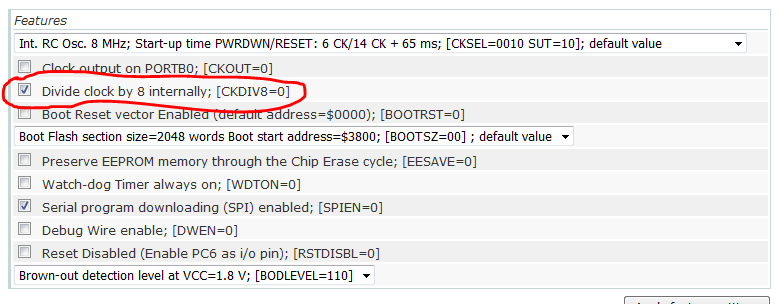
- You noticed the check mark by the 'divide clock by 8' ?
- If you by 'program' normal ftdi flash, then yes. I didn't program bootloader with Arduino.
-
no problem :) yes, it sounds ok...that's how I do too. But I don't use mysbootloader, i use dualoptiboot (sensebender bootloader). for the hex/bin fuse notation, I use hexa.
Is there a reason to use dualoptiboot over MYSBootloader or is that just something you did for no reason?
Did you use Arduino IDE to burn your bootloader, if so then i can confirm its okay to use Hexa for my board with arduino IDE, if you didn't i will have to convert it to normal binary.
I have just realised that you burn your bootloader with the check mark of 8MHz but then the board.txt is configured to set it to 1MHz, is that what you're trying to tell me? I'm not too sure on your last point, i don't get what you're trying to say if i'm honest, could you elaborate a little? Sorry.
-
@samuel235: yes, always good reasons ;) I have tried both. both works well. I like the "buffer style" of dualoptiboot. plus no mysensors lib in bootloader, few others reasons...but mysbootloader is very cool too and simple. So don't worry about this :) it's a matter of taste, each have their pros&cons.
Yes, use arduino ide to burn bootloader + hexa is ok. -
@samuel235: yes, always good reasons ;) I have tried both. both works well. I like the "buffer style" of dualoptiboot. plus no mysensors lib in bootloader, few others reasons...but mysbootloader is very cool too and simple. So don't worry about this :) it's a matter of taste, each have their pros&cons.
Yes, use arduino ide to burn bootloader + hexa is ok.@scalz - Perfect. I will see how i get on with the MYSBootloader style. Soon as i get back i will burn these settings to my uC and see how i get on. I will come back with the results when i'm done. :)
MySensors 2.1.1
Controller - OpenHAB (Virtual Machine)
Gateway - Arduino Mega MQTT Gateway W5100 -
@samuel235: don't worry about 1mhz...there is no big difference 1Mhz vs 8Mhz at 3V in deepsleep mode. In deepsleep mode, at 3V 8Mhz internal rc, you can get 140nA. So you can't have such interesting diff.
In other hand, if node is wake up, you are in mA range, and here it can be interesting to play between clock and voltage ;) you can do it on the fly in sketch and it's good to know that for timing things, atmel clock and voltage are linked.
So i would suggest you to stay with internal rc 8Mhz, BOD 1.8V and MYSBootloader. If I remember right it should be ok. Other thing good to know, you can disable BOD=0V when in deepsleepmode (this is done like this in lib I think), but it's not a good practice to disable it when wake up. Keep 1.8V limit, it can prevent some bugs..All is described in datasheet ;)Another thing good to know, as I see lot of peope estimation for coincell...there are lot of chance that you can't get the full coincell capacity, depending on the application, the use. A common "prevision is to plan 80% of its capacity. It's due to the rate of discharge of battery and coincell's one is small..
There are lot of others resources on the subjects but here few links :
https://www.dmcinfo.com/Portals/0/Blog Files/High pulse drain impact on CR2032 coin cell battery capacity.pdf
http://www.embedded.com/electronics-blogs/break-points/4429960/How-much-energy-can-you-really-get-from-a-coin-cell-
http://www.ti.com/lit/wp/swra349/swra349.pdf- Don't know if good practice or not, but I run 328p + nRF down to 1.6V very stable. Could depend on a lot things and conditions of course. You said "some bugs" - do you know more what risks there are? Permanent damages etc?
- Do you know if the 'Divide clock by 8" (8MHz or 1MHz) also can be changed on-fly-with code? If so, does it matter which speed set by fuse and thus used at start-up?
- Great thanks for the coin cell info!
-
@scalz - Perfect. I will see how i get on with the MYSBootloader style. Soon as i get back i will burn these settings to my uC and see how i get on. I will come back with the results when i'm done. :)
@samuel235 I meant that you should untick this to use 8MHz. Provided that you don't change it on-the-fly somehow.
-
@scalz - Perfect. I will see how i get on with the MYSBootloader style. Soon as i get back i will burn these settings to my uC and see how i get on. I will come back with the results when i'm done. :)
@samuel235 Sorry for not elaborating. I've been mobile all day until now. And my phone also seems to have a few issues with the forum.
-
@m26872 Ahh right okay, good job i caught your reply before burning it haha! So if i set it to 8MHz internal with 64ms delay and untick that divide by 8 option, that'll be good?
MySensors 2.1.1
Controller - OpenHAB (Virtual Machine)
Gateway - Arduino Mega MQTT Gateway W5100 -
@m26872 Ahh right okay, good job i caught your reply before burning it haha! So if i set it to 8MHz internal with 64ms delay and untick that divide by 8 option, that'll be good?
Yes. but don't forget to enable the boot reset vector.
-
@m26872 Ahh right okay, good job i caught your reply before burning it haha! So if i set it to 8MHz internal with 64ms delay and untick that divide by 8 option, that'll be good?
@samuel235 I have not checked if the bootloader size and baud rate matches fuse settings.
-
- for bod=0v, problems could be flash corruption for instance..so it's good to know (it's explained in datasheet that for instance it ensures that a flash write is completely done before reset, I think it makes sense, plus I imagine that there are some internal things with voltage levels related stuff. but I'm not a guru on this....). So my interpretation is sometimes we don't care about it for sleepmode, for instance, and sometimes in wakeup, it's important or not, depending of tasks involved...
maybe I should have said a good practice is to know what you do, lol! - for prescaler, are you asking for something like this : http://www.gammon.com.au/forum/?id=11497&reply=7#reply7
- glad to share what I learn :)
- for bod=0v, problems could be flash corruption for instance..so it's good to know (it's explained in datasheet that for instance it ensures that a flash write is completely done before reset, I think it makes sense, plus I imagine that there are some internal things with voltage levels related stuff. but I'm not a guru on this....). So my interpretation is sometimes we don't care about it for sleepmode, for instance, and sometimes in wakeup, it's important or not, depending of tasks involved...
-
- for bod=0v, problems could be flash corruption for instance..so it's good to know (it's explained in datasheet that for instance it ensures that a flash write is completely done before reset, I think it makes sense, plus I imagine that there are some internal things with voltage levels related stuff. but I'm not a guru on this....). So my interpretation is sometimes we don't care about it for sleepmode, for instance, and sometimes in wakeup, it's important or not, depending of tasks involved...
maybe I should have said a good practice is to know what you do, lol! - for prescaler, are you asking for something like this : http://www.gammon.com.au/forum/?id=11497&reply=7#reply7
- glad to share what I learn :)
@scalz .
maybe I should have said a good practice is to know what you do, lol!
l don't fulfil that either, lol! :smiley:
Thanks for the prescaler info. Seems like a yes - it can be changed on-the-fly, but for me it's a No. I won't even dare to think of consequences for the rest of the software.
- for bod=0v, problems could be flash corruption for instance..so it's good to know (it's explained in datasheet that for instance it ensures that a flash write is completely done before reset, I think it makes sense, plus I imagine that there are some internal things with voltage levels related stuff. but I'm not a guru on this....). So my interpretation is sometimes we don't care about it for sleepmode, for instance, and sometimes in wakeup, it's important or not, depending of tasks involved...
-
@samuel235 I have not checked if the bootloader size and baud rate matches fuse settings.
@m26872 said:
@samuel235 I have not checked if the bootloader size and baud rate matches fuse settings.
I'm not 100% sure of what you mean here, on the fuse calculator there is not an option to specify the baud rate.... As for the bootloader size, the calculator is set to "Boot Flash section size=2048 words Boot start address=$3800; [BOOTSZ=00]". As this is the highest it can be I'm assuming it is correct, however i will try and check the size of the MYSBootloader.hex size and see if it is below 2048 words (Is this what this setting means?).
MySensors 2.1.1
Controller - OpenHAB (Virtual Machine)
Gateway - Arduino Mega MQTT Gateway W5100 -
@m26872 said:
@samuel235 I have not checked if the bootloader size and baud rate matches fuse settings.
I'm not 100% sure of what you mean here, on the fuse calculator there is not an option to specify the baud rate.... As for the bootloader size, the calculator is set to "Boot Flash section size=2048 words Boot start address=$3800; [BOOTSZ=00]". As this is the highest it can be I'm assuming it is correct, however i will try and check the size of the MYSBootloader.hex size and see if it is below 2048 words (Is this what this setting means?).
@samuel235 No, but bootloader and boards.txt must have same buad rate. I think you already have the correct though since 8MHz is pretty much standard clock speed. Slower clock would require lower buad rate.
-
@samuel235 No, but bootloader and boards.txt must have same buad rate. I think you already have the correct though since 8MHz is pretty much standard clock speed. Slower clock would require lower buad rate.
@m26872 Is there a way to read the .hex file to see the specified baud rate before i go and brick the chip? Also, just to confirm, i have to burn the fuse settings in AVRDUDE then burn the bootloader with arduino IDE. Is there anything I'm failing to understand, i only have one more uC here at the moment and i don't want to brick several of them :(
MySensors 2.1.1
Controller - OpenHAB (Virtual Machine)
Gateway - Arduino Mega MQTT Gateway W5100 -
@m26872 Is there a way to read the .hex file to see the specified baud rate before i go and brick the chip? Also, just to confirm, i have to burn the fuse settings in AVRDUDE then burn the bootloader with arduino IDE. Is there anything I'm failing to understand, i only have one more uC here at the moment and i don't want to brick several of them :(
@samuel235 Sorry, I can't help you further. I don't know for sure about these things.
-
@samuel235 Sorry, I can't help you further. I don't know for sure about these things.
@m26872 - That is okay, I think I'm pretty safe to assume that it is correct as it is what is provided on Tekka's guide. So I'm going to attempt to burn the fuses at E2 D8 FE. Once I've done that (and it works fine), Arduino IDE should burn the bootloader onto the uC without an issue and then i can just upload a arduino sketch, right? o.O
-
I've just written the fuse settings and got this log report:
avrdude.exe: set SCK frequency to 187500 Hz
avrdude.exe: AVR device initialized and ready to accept instructions

Reading | ################################################## | 100% -0.00s

avrdude.exe: Device signature = 0x1e950f
avrdude.exe: reading input file "0xE2"
avrdude.exe: writing lfuse (1 bytes):

Writing | ################################################## | 100% -0.00s

avrdude.exe: 1 bytes of lfuse written
avrdude.exe: verifying lfuse memory against 0xE2:
avrdude.exe: load data lfuse data from input file 0xE2:
avrdude.exe: input file 0xE2 contains 1 bytes
avrdude.exe: reading on-chip lfuse data:

Reading | ################################################## | 100% -0.00s

avrdude.exe: verifying ...
avrdude.exe: 1 bytes of lfuse verified
avrdude.exe: reading input file "0xD8"
avrdude.exe: writing hfuse (1 bytes):

Writing | ################################################## | 100% 0.02s

avrdude.exe: 1 bytes of hfuse written
avrdude.exe: verifying hfuse memory against 0xD8:
avrdude.exe: load data hfuse data from input file 0xD8:
avrdude.exe: input file 0xD8 contains 1 bytes
avrdude.exe: reading on-chip hfuse data:

Reading | ################################################## | 100% 0.00s

avrdude.exe: verifying ...
avrdude.exe: 1 bytes of hfuse verified
avrdude.exe: reading input file "0xFE"
avrdude.exe: writing efuse (1 bytes):

Writing |  ***failed;
################################################## | 100% 0.09s

avrdude.exe: 1 bytes of efuse written
avrdude.exe: verifying efuse memory against 0xFE:
avrdude.exe: load data efuse data from input file 0xFE:
avrdude.exe: input file 0xFE contains 1 bytes
avrdude.exe: reading on-chip efuse data:

Reading | ################################################## | 100% 0.00s

avrdude.exe: verifying ...
avrdude.exe: verification error, first mismatch at byte 0x0000
             0x06 != 0xfe
avrdude.exe: verification error; content mismatch

avrdude.exe done.  Thank you.
I then checked the fuses by reading them. I can confirm it has written the Low and the High fuse but as the log says, it failed to write the extended. So I went to the calculator site and read the following (This is what i was asking about hex vs binary for):
"Note that some numerical values refer to fuses containing undefined bits (set to '1' here). Depending on the target device these fuse bits will be read either as '0' or '1'. Verification errors will occur if the values are read back with undefined bits set to '0'. Everything is fine if the values read from the device are either the same as programmed, or the following values (undefined set to '0'): Extended: 0x06."
I then attempted to burn the bootloader, assuming the error is fine to skip (as the fuse calculator said), but it gave me the same error of:
avrdude: verification error, first mismatch at byte 0x0000
         0x06 != 0xfe
avrdude: verification error; content mismatch
So basically, telling me that my boards.txt is telling the IDE that the fuse should be FE, but its 06.
-
Looks like ext fuse is already 0x06 and you only need to change your board.txt to the same. I've never heard before that the 0xFE type of writing should work in avrdude/Arduino IDE.
-
Looks like ext fuse is already 0x06 and you only need to change your board.txt to the same. I've never heard before that the 0xFE type of writing should work in avrdude/Arduino IDE.
I went ahead and changed my board.txt to reflect 0x06, to check. It passed through and burnt the bootloader. However, if i try to upload a sketch (using the FTDI adapter that i have, this) I get a timing error. How do i upload a sketch to the chip with the ISP connection (just to test if my FTDI pins are wired incorrectly). This is my log from arduino IDE:
Sketch uses 12,610 bytes (41%) of program storage space. Maximum is 30,720 bytes.
Global variables use 398 bytes (19%) of dynamic memory, leaving 1,650 bytes for local variables. Maximum is 2,048 bytes.
avrdude: stk500_recv(): programmer is not responding
avrdude: stk500_getsync() attempt 1 of 10: not in sync: resp=0x7c
avrdude: stk500_recv(): programmer is not responding
avrdude: stk500_getsync() attempt 2 of 10: not in sync: resp=0x7c
avrdude: stk500_recv(): programmer is not responding
avrdude: stk500_getsync() attempt 3 of 10: not in sync: resp=0x7c
avrdude: stk500_recv(): programmer is not responding
avrdude: stk500_getsync() attempt 4 of 10: not in sync: resp=0x7c
avrdude: stk500_recv(): programmer is not responding
avrdude: stk500_getsync() attempt 5 of 10: not in sync: resp=0x7c
avrdude: stk500_recv(): programmer is not responding
avrdude: stk500_getsync() attempt 6 of 10: not in sync: resp=0x7c
avrdude: stk500_recv(): programmer is not responding
avrdude: stk500_getsync() attempt 7 of 10: not in sync: resp=0x7c
avrdude: stk500_recv(): programmer is not responding
avrdude: stk500_getsync() attempt 8 of 10: not in sync: resp=0x7c
avrdude: stk500_recv(): programmer is not responding
avrdude: stk500_getsync() attempt 9 of 10: not in sync: resp=0x7c
avrdude: stk500_recv(): programmer is not responding
avrdude: stk500_getsync() attempt 10 of 10: not in sync: resp=0x7c
Problem uploading to board.  See http://www.arduino.cc/en/Guide/Troubleshooting#upload for suggestions.
"programmer is not responding" - I was asking myself "Would this mean that arduino IDE can't use avrdude for some reason?" but then i figured that it used it to burn the bootloader so that isnt right. Is it trying to find the ISP programmer and cant because i'm connected through FTDI maybe?