In wall light switch node - Custom PCB
-
Looks like ext fuse is already 0x06 and you only need to change your board.txt to the same. I've never heard before that the 0xFE type of writing should work in avrdude/Arduino IDE.
I went ahead and changed my board.txt to reflect 0x06, to check. It passed through and burnt the bootloader. However, if i try to upload a sketch (using the FTDI adapter that i have, this) I get a timing error. How do i upload a sketch to the chip with the ISP connection (just to test if my FTDI pins are wired incorrectly). This is my log from arduino IDE:
Sketch uses 12,610 bytes (41%) of program storage space. Maximum is 30,720 bytes.
Global variables use 398 bytes (19%) of dynamic memory, leaving 1,650 bytes for local variables. Maximum is 2,048 bytes.
avrdude: stk500_recv(): programmer is not responding
avrdude: stk500_getsync() attempt 1 of 10: not in sync: resp=0x7c
avrdude: stk500_recv(): programmer is not responding
avrdude: stk500_getsync() attempt 2 of 10: not in sync: resp=0x7c
avrdude: stk500_recv(): programmer is not responding
avrdude: stk500_getsync() attempt 3 of 10: not in sync: resp=0x7c
avrdude: stk500_recv(): programmer is not responding
avrdude: stk500_getsync() attempt 4 of 10: not in sync: resp=0x7c
avrdude: stk500_recv(): programmer is not responding
avrdude: stk500_getsync() attempt 5 of 10: not in sync: resp=0x7c
avrdude: stk500_recv(): programmer is not responding
avrdude: stk500_getsync() attempt 6 of 10: not in sync: resp=0x7c
avrdude: stk500_recv(): programmer is not responding
avrdude: stk500_getsync() attempt 7 of 10: not in sync: resp=0x7c
avrdude: stk500_recv(): programmer is not responding
avrdude: stk500_getsync() attempt 8 of 10: not in sync: resp=0x7c
avrdude: stk500_recv(): programmer is not responding
avrdude: stk500_getsync() attempt 9 of 10: not in sync: resp=0x7c
avrdude: stk500_recv(): programmer is not responding
avrdude: stk500_getsync() attempt 10 of 10: not in sync: resp=0x7c
Problem uploading to board.  See http://www.arduino.cc/en/Guide/Troubleshooting#upload for suggestions.
"programmer is not responding" - I was asking myself "Would this mean that arduino IDE can't use avrdude for some reason?" but then i figured that it used it to burn the bootloader so that isnt right. Is it trying to find the ISP programmer and cant because i'm connected through FTDI maybe?
-
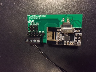
I have just remembered that if you go to the file menu in Arduino IDE you get the option to upload using programmer. I have just done this through my SPI programmer, it has uploaded correctly. I will now solder the nRF module onto the board and i will report back with my results. Crosses fingers
-
BINGO!!
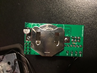
We have a working coin cell powered light switch.
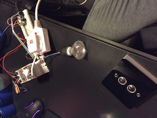
I will upload some decent images later on tonight or tomorrow.
I'de just like to talk everyone that has contributed to this thread/post and enabled me to create my first of many embedded projects. I'm applying for a University course in september for Computer Science (Smart Technologies), all about embedded systems, drones, home automation etc etc. This is just the beginning!
I'll get this project up on OpenHardware.io asap as Version 1 and we can build on this as a base plate for futher projects.
-
Now, the next two steps I'm interested in taking is to get this working with 2 switches (Software modification, should be simple) and then to have it report its remaining power every 30 minutes to allow me to set up notifications through openhab to alert me to change the batteries so I'm not left with no light switch.
-
It would appear that I'm having a timing issue with uploading via the FTDI adapter. Would this be down to the speed of the uC effecting the RX and TX connections?
MySensors 2.1.1
Controller - OpenHAB (Virtual Machine)
Gateway - Arduino Mega MQTT Gateway W5100 -
It would appear that I'm having a timing issue with uploading via the FTDI adapter. Would this be down to the speed of the uC effecting the RX and TX connections?
This post is deleted! -
It would appear that I'm having a timing issue with uploading via the FTDI adapter. Would this be down to the speed of the uC effecting the RX and TX connections?
@samuel235 Are you trying to upload with Ftdi serial to MYSbootloader? I think it's only for OTA uploads, if you read here.
-
@samuel235 Are you trying to upload with Ftdi serial to MYSbootloader? I think it's only for OTA uploads, if you read here.
@m26872 - Thank you for pointing this out to me. I'm unsure why I haven't stumbled across that thread/topic today of all days, been searching and reading about MYSBootloader all day >.<
From personal experience, would you advise any other bootloader, I'm guessing you're going to tell me about the one you are using. Could you link any information for me to check out regarding your choice of bootloader?
Am I correct in recalling you're using DualOptiBoot?
Does DualOptiBoot need external memory/flash?MySensors 2.1.1
Controller - OpenHAB (Virtual Machine)
Gateway - Arduino Mega MQTT Gateway W5100 -
@m26872 - Thank you for pointing this out to me. I'm unsure why I haven't stumbled across that thread/topic today of all days, been searching and reading about MYSBootloader all day >.<
From personal experience, would you advise any other bootloader, I'm guessing you're going to tell me about the one you are using. Could you link any information for me to check out regarding your choice of bootloader?
Am I correct in recalling you're using DualOptiBoot?
Does DualOptiBoot need external memory/flash?@samuel235 No, I use plain optiboot, but I couldn't find a suiteable precompiled one for you. DualOptiboot requires external flash as you say.
It's been a while since I played with bootloaders, but I think normal 8MHz Arduino Pro Mini bootloader would work for you with internal clock as well. It's this [ATmegaBOOT_168_atmega328_pro_8MHz.hex ] and I can find it in my "C:\Program Files\Arduino\hardware\arduino\avr\bootloaders\atmega" -folder, should be about the same for you I think. Try fuse settings E2-DA-06 (Lo-Hi-Ex) and rest of the boards.txt-settings from ArduinoProMini 3.3V 8MHz. -
@samuel235 No, I use plain optiboot, but I couldn't find a suiteable precompiled one for you. DualOptiboot requires external flash as you say.
It's been a while since I played with bootloaders, but I think normal 8MHz Arduino Pro Mini bootloader would work for you with internal clock as well. It's this [ATmegaBOOT_168_atmega328_pro_8MHz.hex ] and I can find it in my "C:\Program Files\Arduino\hardware\arduino\avr\bootloaders\atmega" -folder, should be about the same for you I think. Try fuse settings E2-DA-06 (Lo-Hi-Ex) and rest of the boards.txt-settings from ArduinoProMini 3.3V 8MHz.@m26872 - Ahh the generic arduino bootloader... I will have a look into using that tomorrow. As the MYSController gets more feature rich and support i will use that setup, however i love OpenHAB way too much to switch over right now.
-
@m26872 - I've just spent a few minutes looking through my boards.txt and i came across:
######## Settings for

ATmega328 8MHz Internal clock
atmega328bb.name=ATmega328 on a breadboard (8MHz internal clock)
atmega328bb.upload.protocol=stk500
atmega328bb.upload.maximum_size=30720
atmega328bb.upload.speed=57600
atmega328bb.bootloader.low_fuses=0xE2
atmega328bb.bootloader.high_fuses=0xDA
atmega328bb.bootloader.extended_fuses=0x05
atmega328bb.bootloader.path=arduino:atmega
atmega328bb.bootloader.file=ATmegaBOOT_168_atmega328_pro_8MHz.hex
atmega328bb.bootloader.unlock_bits=0x3F
atmega328bb.bootloader.lock_bits=0x0F
atmega328bb.build.mcu=atmega328p
atmega328bb.build.f_cpu=8000000L
atmega328bb.build.core=arduino:arduino
atmega328bb.build.variant=arduino:standard
Then out of interest I thought I would look at the bootloader that you suggested, to see what difference there would be. Turns out I was actually looking at it without knowing. I have a feeling that if I change the fuse settings to those that i am using now with MYSBootloader, I will be set to go.
The High Fuse setting you provided enables 1024 words in the boot flash section, a couple of questions about this:
- Is this defining the size of the area needed for the bootloader section on the built in memory (So smaller this is set to, as long as the bootloader will fit, the more room I will have for a sketch)?
- How do i find out the 'word size' of the bootloader (if the first question is correct method) so I can determine if the 1024 is big enough? I would rather know how to work this out rather than just assuming that it is because it is specified as that as default.
I was going to leave my fuses where they were at (E2, D8, 06 as LO:HI:EX) but if I can change the boot size setting, that would allow a bigger room for my sketches = Win Win!
I'm still slightly confused as to not being able to burn my extended fuse. I have read somewhere (lost the page) about not being possible to burn an EX fuse on a ATmega328p, which i find very hard to believe.
MySensors 2.1.1
Controller - OpenHAB (Virtual Machine)
Gateway - Arduino Mega MQTT Gateway W5100 -
@m26872 - I've just spent a few minutes looking through my boards.txt and i came across:
######## Settings for

ATmega328 8MHz Internal clock
atmega328bb.name=ATmega328 on a breadboard (8MHz internal clock)
atmega328bb.upload.protocol=stk500
atmega328bb.upload.maximum_size=30720
atmega328bb.upload.speed=57600
atmega328bb.bootloader.low_fuses=0xE2
atmega328bb.bootloader.high_fuses=0xDA
atmega328bb.bootloader.extended_fuses=0x05
atmega328bb.bootloader.path=arduino:atmega
atmega328bb.bootloader.file=ATmegaBOOT_168_atmega328_pro_8MHz.hex
atmega328bb.bootloader.unlock_bits=0x3F
atmega328bb.bootloader.lock_bits=0x0F
atmega328bb.build.mcu=atmega328p
atmega328bb.build.f_cpu=8000000L
atmega328bb.build.core=arduino:arduino
atmega328bb.build.variant=arduino:standard
Then out of interest I thought I would look at the bootloader that you suggested, to see what difference there would be. Turns out I was actually looking at it without knowing. I have a feeling that if I change the fuse settings to those that i am using now with MYSBootloader, I will be set to go.
The High Fuse setting you provided enables 1024 words in the boot flash section, a couple of questions about this:
- Is this defining the size of the area needed for the bootloader section on the built in memory (So smaller this is set to, as long as the bootloader will fit, the more room I will have for a sketch)?
- How do i find out the 'word size' of the bootloader (if the first question is correct method) so I can determine if the 1024 is big enough? I would rather know how to work this out rather than just assuming that it is because it is specified as that as default.
I was going to leave my fuses where they were at (E2, D8, 06 as LO:HI:EX) but if I can change the boot size setting, that would allow a bigger room for my sketches = Win Win!
I'm still slightly confused as to not being able to burn my extended fuse. I have read somewhere (lost the page) about not being possible to burn an EX fuse on a ATmega328p, which i find very hard to believe.
@samuel235 said:
- Is this defining the size of the area needed for the bootloader section on the built in memory (So smaller this is set to, as long as the bootloader will fit, the more room I will have for a sketch)?
Yes.
- How do i find out the 'word size' of the bootloader (if the first question is correct method) so I can determine if the 1024 is big enough? I would rather know how to work this out rather than just assuming that it is because it is specified as that as default.
I don't have the tool or knowledge for that. Should be doable by removing indices and count the bytes in hex-file. But for me it's not a big deal to just use the size settings recommended for a particular bootloader. And in this case it´s stock Arduino, so why question it.
I'm still slightly confused as to not being able to burn my extended fuse. I have read somewhere (lost the page) about not being possible to burn an EX fuse on a ATmega328p, which i find very hard to believe.
So the '0x06'-kind of notation didn't work either? Strange.
-
@samuel235 said:
- Is this defining the size of the area needed for the bootloader section on the built in memory (So smaller this is set to, as long as the bootloader will fit, the more room I will have for a sketch)?
Yes.
- How do i find out the 'word size' of the bootloader (if the first question is correct method) so I can determine if the 1024 is big enough? I would rather know how to work this out rather than just assuming that it is because it is specified as that as default.
I don't have the tool or knowledge for that. Should be doable by removing indices and count the bytes in hex-file. But for me it's not a big deal to just use the size settings recommended for a particular bootloader. And in this case it´s stock Arduino, so why question it.
I'm still slightly confused as to not being able to burn my extended fuse. I have read somewhere (lost the page) about not being possible to burn an EX fuse on a ATmega328p, which i find very hard to believe.
So the '0x06'-kind of notation didn't work either? Strange.
@m26872 said:
And in this case it´s stock Arduino, so why question it.
I'm not questioning it, I just wanted to learn how to do it for if i ever came across a need to modify a bootloader i would then know how to record its size for the fuse burning.
So the '0x06'-kind of notation didn't work either? Strange.
When i set the boards.txt file to read 0x06 it worked perfect, which insinuates that it couldn't burn the chosen BoD, even though the fuse calculator says to ignore the error of the extended fuse, it should burn it even though it gives the error. I'm interested in trying to burn the extended fuse in normal binary rather than hexa. But i doubt it would work anyway.
-
It has just clicked inside my busy mind that 0x06 in binary is the same as 0xFE in Hexa. How embarrassed am I now after many questions and hours thinking about the extended fuse value. I'm now assuming that it returns the error because it is already set at that fuse :flushed:
-
So, i have it working using the following board.txt config:
######## Settings for

ATmega328 8MHz Internal clock Brown-out detection 1.8v
atmega328bb.name=ATmega328 on a breadboard (8MHz internal clock) BoD1.8
atmega328bb.upload.tool=avrdude
atmega328bb.upload.protocol=stk500
atmega328bb.upload.maximum_size=30720
atmega328bb.upload.speed=57600
atmega328bb.bootloader.tool=avrdude
atmega328bb.bootloader.low_fuses=0xE2
atmega328bb.bootloader.high_fuses=0xDA
atmega328bb.bootloader.extended_fuses=0x06
atmega328bb.bootloader.path=arduino:atmega
atmega328bb.bootloader.file=atmega/ATmegaBOOT_168_atmega328_pro_8MHz.hex
atmega328bb.bootloader.unlock_bits=0x3F
atmega328bb.bootloader.lock_bits=0x3F
atmega328bb.build.mcu=atmega328p
atmega328bb.build.f_cpu=8000000L
atmega328bb.build.core=arduino:arduino
atmega328bb.build.variant=arduino:standard
However, no matter what I did I couldn't get it to upload via FTDI. I've tried looking at the Arduino Pro Mini settings in boards.txt to see what 'upload.tool' it uses, AVRDUDE, same as i specified. I also then went to the google docs for the boards.txt reference file, that advises everything i did too. I'm a little stumped. All that i can think of is that i have wired it incorrectly on the pcb. Whats your thoughts on this?
-
@m26872 said:
And in this case it´s stock Arduino, so why question it.
I'm not questioning it, I just wanted to learn how to do it for if i ever came across a need to modify a bootloader i would then know how to record its size for the fuse burning.
So the '0x06'-kind of notation didn't work either? Strange.
When i set the boards.txt file to read 0x06 it worked perfect, which insinuates that it couldn't burn the chosen BoD, even though the fuse calculator says to ignore the error of the extended fuse, it should burn it even though it gives the error. I'm interested in trying to burn the extended fuse in normal binary rather than hexa. But i doubt it would work anyway.
@samuel235 said:
I'm not questioning it,
I'm not saying you do, I just told how I think of it.
I'm interested in trying to burn the extended fuse in normal binary rather than hexa.
Why, when the result is exactly the same?
Also, I'm not familiar with from where the "binary or hexa" comes from? They're both hexadecimal notation as far as I can see. -
I'm not sure what is your problem with ftdi.maybe wirings...do you have cts to gnd, and of course dtr to dtr, only one vcc active...??? Maybe you should try to burn original arduino ide bootloader and then ftdi upload attempts. If it still doesn't work, it could be the wirings...
for hexa vs binary..in some case binary notation can be useful, but for fuses, I prefer hexa: shorter, no possibility of mistakes by missing/miscounting one "1" or "0" bit ;) -
@m26872 - I wanted to try it because i'm sure i read somewhere that the ATmega328 can't accept Hexa as fuses. But i doubt that information is valid if i'm honest with you.
@scalz - I have dtr to dtr and cts linked to ground. I also only have one VCC pin (which obviously goes to VCC). I'll be perfectly honest with you; the boart.txt setting i posted above, i thought that was using the arduino .hex bootloader, please inform me if i'm in correct in that.
-
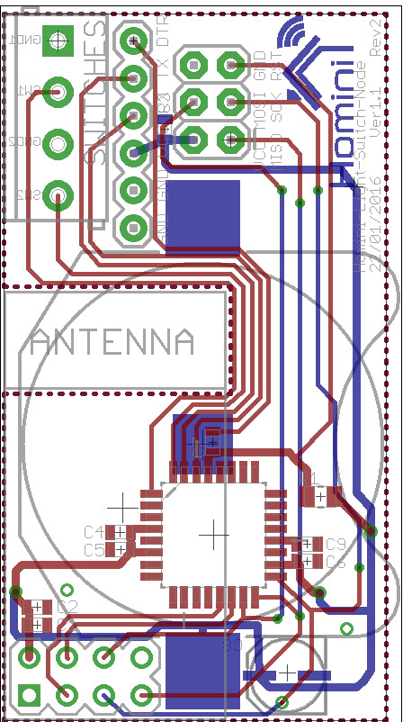
This is the board layout, if you guys can see any issues with my FTDI connections/pinout please advice me that you do, I will get that sorted for revison 3 of the board. If i'm honest, I don't mind burning the sketches with the ISP programmer everytime, so I'm very tempted to remove the FTDI, allowing a smaller board still.
MySensors 2.1.1
Controller - OpenHAB (Virtual Machine)
Gateway - Arduino Mega MQTT Gateway W5100 -
This is the board layout, if you guys can see any issues with my FTDI connections/pinout please advice me that you do, I will get that sorted for revison 3 of the board. If i'm honest, I don't mind burning the sketches with the ISP programmer everytime, so I'm very tempted to remove the FTDI, allowing a smaller board still.
@samuel235 How do you debug through ISP ?
Have you tested your FTDI USB-serial converter with ArduinoProMini or something?