In wall light switch node - Custom PCB
-
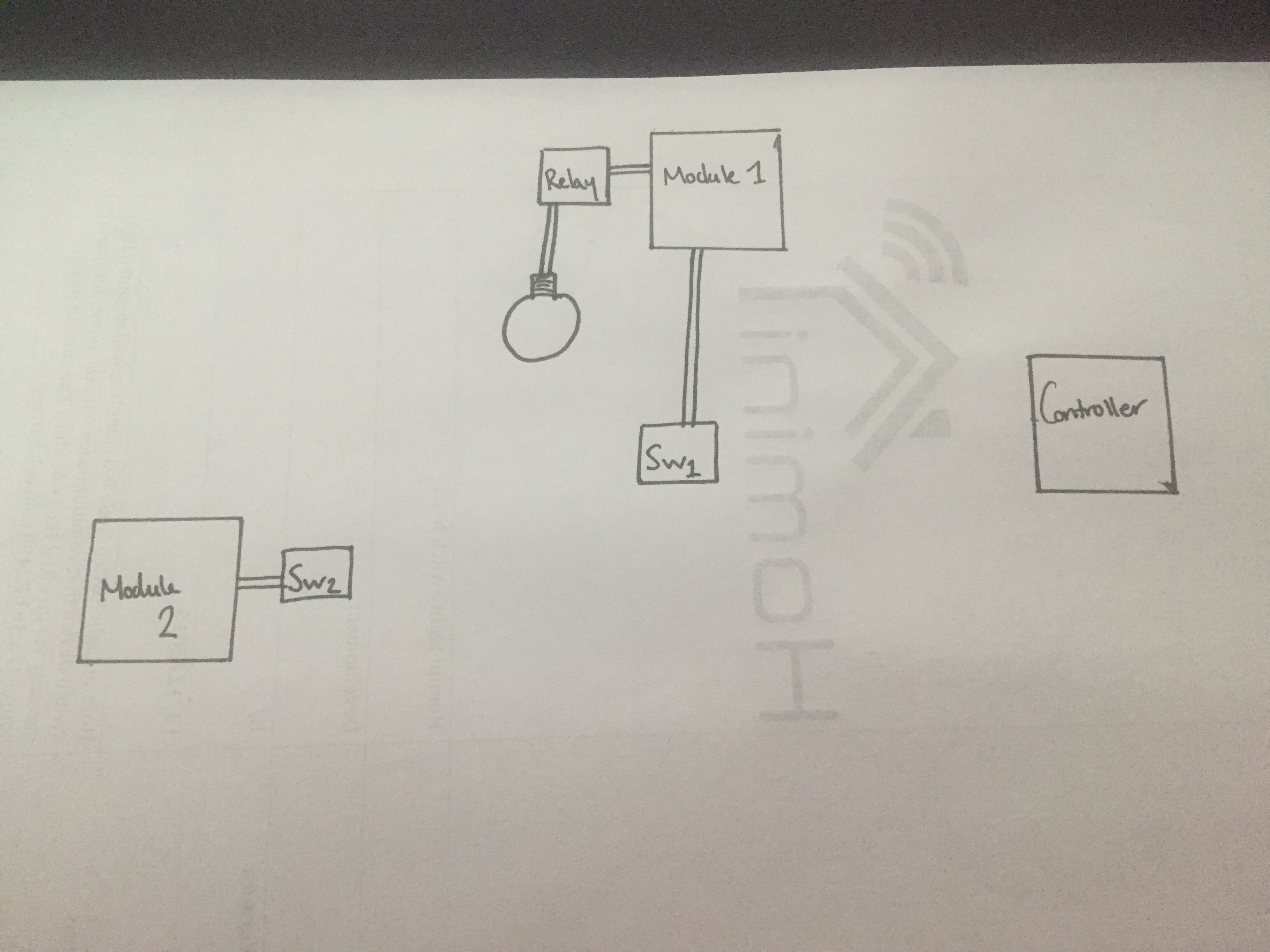
This is my current setup @Sefi-Ninio. The controller is an obvious one for you. Module 1 is currently just an arduino nano connected to a SSR with a NPN transistor (serving as an amp, just to relieve the arduino from harder work than needed to turn the relay). I will at some point have this all on one board, this is designed to be placed in the ceiling close to the light itself. Depending on your needs, this can run either of the MySensors sketches, Relay or RelayWithButtonActuator. I have chose to have mine run the second, so i have a locally connected switch to this module to operate the light from upstairs, this will work whether or not the controller is alive. If you only need one switch and can run a cable/wire, this is your best bet. If not you can either use my board as a 'wireless switch' or as a slave switch for the light.
My board will enable you to control the light module through the controller, however if this controller goes offline, obviously my board will not work. So, if do only need one switch and can run a cable from the light to the switch go with my first example, if you need a secondary switch or even just a case of a wireless switch then go with my board.
-
This is my current setup @Sefi-Ninio. The controller is an obvious one for you. Module 1 is currently just an arduino nano connected to a SSR with a NPN transistor (serving as an amp, just to relieve the arduino from harder work than needed to turn the relay). I will at some point have this all on one board, this is designed to be placed in the ceiling close to the light itself. Depending on your needs, this can run either of the MySensors sketches, Relay or RelayWithButtonActuator. I have chose to have mine run the second, so i have a locally connected switch to this module to operate the light from upstairs, this will work whether or not the controller is alive. If you only need one switch and can run a cable/wire, this is your best bet. If not you can either use my board as a 'wireless switch' or as a slave switch for the light.
My board will enable you to control the light module through the controller, however if this controller goes offline, obviously my board will not work. So, if do only need one switch and can run a cable from the light to the switch go with my first example, if you need a secondary switch or even just a case of a wireless switch then go with my board.
Hello, I'm also very interested about light switch, which is connected to controller, topic. I'm freshman at MySensons comunity, so don't judge me if I have silly questions :)
How You was writting in Your last posts, it is possible to use same PCB like RelayWithButtonActuator sketch. Please corect me if I'm wrong. If I want to control 1 light bulb with 1 button, then I connect solid state relay (SSR) to SW1 and button to SW2.
Questions:- Am I right with this description?
- SSR needs 5VDC input, so in same circuit we would need a step up from 3VDC to 5VDC. But if we were using step up, does 3V battery still have long life (about 1years and 4 months theoricaly)?
Another questions with the look ahead of same project. I think it will be interesting @sundberg84 too.
I was thinking how to put everything in one place with same priorities: safe and small as possible node.
I drew an example:
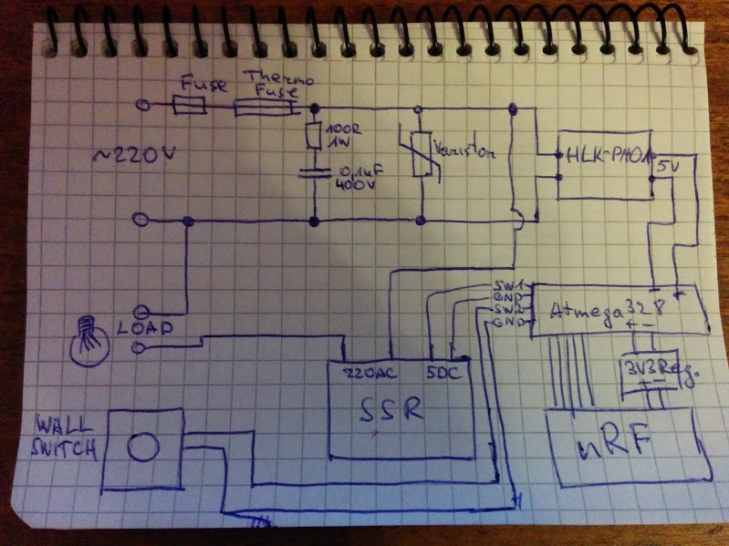
From here I have few questions too:
- I ordered SSR G3MB-202P and in datasheet there was written that it has snubber circuit already. So do I need another snubber circuit near the thermo fuse?
- What would be smarter if we want to make 'universal' PCB for at least 4 switches with buttons: to integrate SSR relays into PCB or make just the connections, like in already made @samuel235 PCB like SW1 and SW2?
Thanks for answers!
-
I'm currently attempting to find a solution to my ISP uploading with the radio attached dilemma.
My initial thought was to have 3 sets of 2pin headers with jumpers on, then remove the jumpers when you need to upload through ISP. But I'm really struggling to do this with the size of the board.
My next thought was to have 3 sets of Surface Mount header pads, then solder them together, then if i needed to use ISP, just de-solder this connection with solder wick, then solder it back together once ISP connection is complete.
The only real need that we would need to upload to this board would be to change the node ID if its set manually (which i do) or to update the sketch with more up to date solutions. The only way around this would be to use a controller such as MysController where you can do OTA uploads, but this would require me to have a crystal on board to allow the use of FTDI to get the bootloader and sketch on in the first place. Am i correct in thinking this, or is there a way to upload just a sketch to the uC through ISP where it allows a bootloader to be present on the uC, as far as i understand when you 'upload using programmer' it uses all of the uC's flash for the program you're loading.
-
Hello, I'm also very interested about light switch, which is connected to controller, topic. I'm freshman at MySensons comunity, so don't judge me if I have silly questions :)
How You was writting in Your last posts, it is possible to use same PCB like RelayWithButtonActuator sketch. Please corect me if I'm wrong. If I want to control 1 light bulb with 1 button, then I connect solid state relay (SSR) to SW1 and button to SW2.
Questions:- Am I right with this description?
- SSR needs 5VDC input, so in same circuit we would need a step up from 3VDC to 5VDC. But if we were using step up, does 3V battery still have long life (about 1years and 4 months theoricaly)?
Another questions with the look ahead of same project. I think it will be interesting @sundberg84 too.
I was thinking how to put everything in one place with same priorities: safe and small as possible node.
I drew an example:
From here I have few questions too:
- I ordered SSR G3MB-202P and in datasheet there was written that it has snubber circuit already. So do I need another snubber circuit near the thermo fuse?
- What would be smarter if we want to make 'universal' PCB for at least 4 switches with buttons: to integrate SSR relays into PCB or make just the connections, like in already made @samuel235 PCB like SW1 and SW2?
Thanks for answers!
Firstly, thank you for showing so much interest!
To answer your questions:
- Yes you're correct, in theory.
- In my relay module i use a NPN transistor to bring the load off of the arduino/uC itself and to create a 'boost' for the SSR to properly register the switch. However, i do use a standard SSR, not a on-board style one. (this is the one i use).
Me and Sundberg have shown interest in each others projects, hopefully soon i will be moving onto a module that will incorporate in-wall powering for itself and its sensors, that i hope to work with @sundberg84 to develop a solution that i have a feeling many of people will like here.
Your next questions:
- I'm not very confident in answering this question right now and i hope that Sundberg will assist you here with that.
- The smart approach (Which i do plan on creating at some point) would be to create a board that has the relays on board along with screw terminals for 4 switches, so one ground and 4 digital input pins. Because these switches will be local to the relays, the board itself wont need to sleep at all, so then this means the only limit on the amount of switch you use are the amount of pins available. Right now my limit of 2 switches is dictated by the amount of interrupt pins we have on board of the ATmega328p-au. If the module sleeps to save energy the only way to have a switch work is to attach it to an interrupt enabled pin, which we only have two of.
There seems to be a slight miss understanding with a few people around here on the duty of this module. This is simply a slave to a relay module because i can not round a cable/wire all the way from the desired location of my relay module, acting as a second switch as i also have a locally connected switch to the relay module, shown in my previous image/sketch.
-
Battery voltage measuring investigations and monitoring methods are now being discussed at http://forum.mysensors.org/topic/3398/another-battery-monitoring-thread/5. This will enable me to have the controller act accordingly when the battery is running low, even have an indicator on the switch itself to let us know when we need to replace the battery before it is too late and we can not use the light switch any more.
Please be sure to add your input on this topic to help us develop this product further.
-
I'm currently researching into capacitive touch sensing. I'm very tempted to create face plates from a 3DPrinter and enable it to have multiple capacitive sensors behind this plate to allow the use as a light switch. This will be an additional option, not necessary for this PCB to work. You will still be able to use a normal switch connected to the PCB. Just would be different software, potentially.
-
Project has been uploaded to https://www.openhardware.io/view/48/Homini-In-Wall-Battery-Powered-Light-Switch-Module
MySensors 2.1.1
Controller - OpenHAB (Virtual Machine)
Gateway - Arduino Mega MQTT Gateway W5100 -
Project has been uploaded to https://www.openhardware.io/view/48/Homini-In-Wall-Battery-Powered-Light-Switch-Module
@Samuel235 Any news regarding the new revision?
-
@Samuel235 Any news regarding the new revision?
@Sefi-Ninio said:
@Samuel235 Any news regarding the new revision?
I'm struggling with time at the monent due to my full time job. I'm currently working on the upload issues. I feel that its the bootloader not matching the avr settings correctly with the upload speeds. @GertSanders has given a couple of bootloader examples for me to try which i will start testing tonight on that for you guys.
-
Currently experiencing some issues with what we speculate to be a fuse burning issue. I'll be troubleshooting further today. Will keep updates coming.
-
Is that related to the circuit for battery level? Or something else?
What are the differences between the current rev. and what you are working on now? -
Is that related to the circuit for battery level? Or something else?
What are the differences between the current rev. and what you are working on now?@Sefi-Ninio said:
Is that related to the circuit for battery level? Or something else?
What are the differences between the current rev. and what you are working on now?It is concerning the serial upload issues i was having. The current revision doesn't include a bootloader and then therefor we can't upload via serial adapter. This in turn makes it unable to program anything once the radio is soldered directly to the board. I'm currently in discussions with GertSanders to try and figure out the issues with my bootloaders. Once this is sorted i will be able to program and debug the node through the serial interface/monitor.
The next step will be to include a basic voltage divider method of reading the battery level i think. I did do various tests about a month ago and i will re-evaluate the situation on that. I may be a simple voltage divider solution or i may go for some exotic method. Even though the power consumption is slightly more heavy on the voltage divider method, i think i will go ahead and choose this method because of its simplicity for new users to just solder a couple of resistors on board. We will see.
I do have another project/module in the design phases and a topic thread located here.
-
I have a problem finding the right wall switch. Normally they are all laid out for 230 volts, making them really big and requiring a lot of depth. Does anyone have experience with low voltage switches, which look nice and can be used for such projects ?
Thanks ! -
I have a problem finding the right wall switch. Normally they are all laid out for 230 volts, making them really big and requiring a lot of depth. Does anyone have experience with low voltage switches, which look nice and can be used for such projects ?
Thanks !@Sander-Teunissen, I have these running on a coin cell battery and the sizes for the overall board are: Height: 16mm, Width: 26mm, Length: 48mm. Please note that these sizes are that of the module without insulation. My current working node has its back covered with some fabric to stop it shorting out on the metal backbox. I need to come up with a solution for this. When i order my 3D Printer i'm hoping to fashion some sort of shielding for the rear.
-
I'm currently waiting on some more components to get this module up and running with thanks to @GertSanders providing the bootloader. All being well we will have it completed in the next month to be running with the radio and allowing ISP and FTDI/Serial uploads with the radio all connected.
Does anyone have any feature requests for this module other than simple battery monitoring?
-
@jeylites, i was going to make a thread on these exact switches soon to discuss the possibility of interfacing them as they run on RF. Keep your eyes open for the thread asap ;).
I would like to make my own switch front with pressure capacitance at some point but thats for another day.
-
UPDATE - Feature upgrades
I have had the materials arrive to attempt to get the latest fixes sorted for this board. Hopefully this will allow us to serial upload while the radio is soldered permanently onto the board. I will update soon as i have attempted this. Keep you posted!
-
@jeylites, i was going to make a thread on these exact switches soon to discuss the possibility of interfacing them as they run on RF. Keep your eyes open for the thread asap ;).
I would like to make my own switch front with pressure capacitance at some point but thats for another day.
@Samuel235 said:
@jeylites, i was going to make a thread on these exact switches soon to discuss the possibility of interfacing them as they run on RF. Keep your eyes open for the thread asap ;).
I would like to make my own switch front with pressure capacitance at some point but thats for another day.
I didn't read this. interesting..one of my current project in progress is exactly this! Designing a special shield for glass plate etc :) the same for controlling one switch or more ;)
I have few Livolo that I have disassembled and looked how it works inside. but I'm not fan of 433mhz radio (or that would need some rflink). I'm actually trying to decidde the best way, if I want to hack it, or if I will do my own switch with glass plate I found. because I would like dimming, rfm69, authentication and my shield... -
@Samuel235 said:
@jeylites, i was going to make a thread on these exact switches soon to discuss the possibility of interfacing them as they run on RF. Keep your eyes open for the thread asap ;).
I would like to make my own switch front with pressure capacitance at some point but thats for another day.
I didn't read this. interesting..one of my current project in progress is exactly this! Designing a special shield for glass plate etc :) the same for controlling one switch or more ;)
I have few Livolo that I have disassembled and looked how it works inside. but I'm not fan of 433mhz radio (or that would need some rflink). I'm actually trying to decidde the best way, if I want to hack it, or if I will do my own switch with glass plate I found. because I would like dimming, rfm69, authentication and my shield...@scalz, If i'm honest I would like to see both. I love to see hacks being perfected, especially in products with such a clean finish as these but then again i also love seeing brand news products being brought to life. Either one you do, i'll be sure to support your ideas!