In wall light switch node - Custom PCB
-
@samuel235: cool.
- I think you need to learn some basic electronics basics guide, it could help you in future to understand because if you want to draw schem, it would be useful, positive feedback ;)
I started to learn elec and uc stuff some years ago(10+), so when I say I am not electronician, it is a small lie :) I am not graduated in this field ;) but my dad, elec engineer, teached me a lot. I am lucky. Now you can have lot infos at sparkfun, adafruit, arduino ....and you are choosing the fun/interesting way, learning learning and learning. - like @m26872 said, it is better, and I like it too when I can, to have footprints.
- for the batt cap, I told you this because of the cr2032 comment..it can prevent the coin cell to discharge too fast. coin cell don't like spikes, this is one of the reason for people choosing alkaline. but you can do lot of stuff with coin cell too. the cap is optional of course.
- If you can have avrspi, better, but if no space. like you said upload bootloader, and then...if you have to reupload it later, just unsolder nrf, not big thing.
- for 0805 or 0603, this is not a question about component cost here...it is much more a question of your soldering skills and available space of course.
I have no problem with 0603, I handsolder some vqfn sensors (very hard stuff...), but what I would advice for noob, a step by step curve. Try 0805 first, then move harder stuff. You will see that you must be careful when soldering atmel tqfp. If all ok, then...pcb are cheap now ;) I hope you have good iron solder, thin wire....
@scalz - This is partially why i'm choosing to do all of this myself, I'm learning electronics while i go. Honestly, its why i have created this topic/thread so i can learn and other can tune in to learn a thing or two as well. I have that Cap wired into the battery if i need it, i will more than likely just put it in anyway to be on the safe side. I think I'm going straight into 0603 SMD tbh, I have a pretty steady hand and have some decent soldering experience. I may need to get myself a expensive/quality soldering iron, i have a cheap(ish) temperature regulated one at the moment. I'm getting some thin solder on order with the parts when i finally order it all.
- I think you need to learn some basic electronics basics guide, it could help you in future to understand because if you want to draw schem, it would be useful, positive feedback ;)
-
cool. so, for soldering, from my own experience, but I will start to use reflow oven, what I can advise you is:
- find a 0.2mm tip for your iron solder. I have a great old weller. but I know someone who have bought a ts100 recently and he is very happy with it! you have large choice to power it, and we can imagine to use lipo with it for ponctual mobile soldering, far better than butane gaz iron solder!. crazy price, quality I don't know but I am very tempted to buy one...
http://www.banggood.com/fr/TS100-Digital-OLED-Programable-Interface-DC-5525-Soldering-Iron-Station-Built-in-STM32-Chip-p-984214.html - a magnifier is a minimum I think. a cheap one is a good start. maybe a 3rd hand..
- thin solder. I use 0.3 but 0.5mm can work I think. Choose good quality for thin solder. some aliexpress thin solder are very bad.
- flux of course. very helpful. I prefer gel or liquid. I don't like aliexpress pen.
- desolder wick. very helpful too.
- tweezers like this for instance:
http://fr.aliexpress.com/item/6pcs-Set-VETUS-Tweezers-Anti-static-ESD-10-15-Tweezers-Set-for-Soldering-Welding-Station/32265054449.html?spm=2114.06010108.3.112.yI04vt&ws_ab_test=searchweb201556_7_79_78_77_82_80_62,searchweb201644_0,searchweb201560_4 - I use isopropil alcool (rubbing alcool I think) to clean my board after soldering..
- solder paste, optional, but helpful sometimes and funny to try
- lots of soldering howto on youtube
- find a 0.2mm tip for your iron solder. I have a great old weller. but I know someone who have bought a ts100 recently and he is very happy with it! you have large choice to power it, and we can imagine to use lipo with it for ponctual mobile soldering, far better than butane gaz iron solder!. crazy price, quality I don't know but I am very tempted to buy one...
-
cool. so, for soldering, from my own experience, but I will start to use reflow oven, what I can advise you is:
- find a 0.2mm tip for your iron solder. I have a great old weller. but I know someone who have bought a ts100 recently and he is very happy with it! you have large choice to power it, and we can imagine to use lipo with it for ponctual mobile soldering, far better than butane gaz iron solder!. crazy price, quality I don't know but I am very tempted to buy one...
http://www.banggood.com/fr/TS100-Digital-OLED-Programable-Interface-DC-5525-Soldering-Iron-Station-Built-in-STM32-Chip-p-984214.html - a magnifier is a minimum I think. a cheap one is a good start. maybe a 3rd hand..
- thin solder. I use 0.3 but 0.5mm can work I think. Choose good quality for thin solder. some aliexpress thin solder are very bad.
- flux of course. very helpful. I prefer gel or liquid. I don't like aliexpress pen.
- desolder wick. very helpful too.
- tweezers like this for instance:
http://fr.aliexpress.com/item/6pcs-Set-VETUS-Tweezers-Anti-static-ESD-10-15-Tweezers-Set-for-Soldering-Welding-Station/32265054449.html?spm=2114.06010108.3.112.yI04vt&ws_ab_test=searchweb201556_7_79_78_77_82_80_62,searchweb201644_0,searchweb201560_4 - I use isopropil alcool (rubbing alcool I think) to clean my board after soldering..
- solder paste, optional, but helpful sometimes and funny to try
- lots of soldering howto on youtube
@scalz Pretty cool list of things there! I'm going to use the soldering iron i have at the moment and see how that stands up to the task. I will be ordering a magnifier, some thin solder, a few tweezers, desolder wick and some alcohol too. I have been doing some pretty basic soldering jobs where i didn't need to pay close attention as much as this in terms of little things like cleaning up the board etc etc. I have soldered and replaced laptop motherboard power connectors and such, completed the PCB Board kits for little projects but nothing as serious as this before. So now is the time my soldering skills are going to be put to the test, and i honestly can't wait! I'm working on my board layout as we speak and i will get this uploaded soon as i am done for a update to the project.
- find a 0.2mm tip for your iron solder. I have a great old weller. but I know someone who have bought a ts100 recently and he is very happy with it! you have large choice to power it, and we can imagine to use lipo with it for ponctual mobile soldering, far better than butane gaz iron solder!. crazy price, quality I don't know but I am very tempted to buy one...
-
I'm very tempted to have some jumper headers or even a dip switch on the board to allow for sketch uploads with the nRF intact. I'm hoping to get some sizings done tomorrow and if i have the room i may have the RF module on a header/socket so i can remove it while uploading a swetch. If not i will have to go with the idea of jumpers or try to rearrange the board to allow a SPI header. I shall see what i can do, upload to this build log and see what you guys think. Again, with shared input we could possibly create a much better suited board then.
Whats your opinions to the jumper pins across the SPI connection on the nRF module to effectivly disconnect the RF while we upload the sketch upgrades?
-
C6 should be in parallel to the battery. In the schematic you show, the C6 would disconnect the battery from Vcc (from DC point of view). If you have Vcc - C6 - battery- GND, then no DC current will flow from Vcc to GND. Is should be:
Vcc -+- battery -+- GND
Vcc -+- C6 -+- GND -
C6 should be in parallel to the battery. In the schematic you show, the C6 would disconnect the battery from Vcc (from DC point of view). If you have Vcc - C6 - battery- GND, then no DC current will flow from Vcc to GND. Is should be:
Vcc -+- battery -+- GND
Vcc -+- C6 -+- GND@GertSanders I should remove C6 from the battery to make VCC - BATT - GND. Then put it like i have done with C5, as VCC - C6 - GND. Have i understood you correctly?
-
C6 // Batt
one side of C6 to VCC/Vbat
other side of C6 to GND -
@samuel235 you understand correctly :-)
-
I have added a ISP header, 100uF cap through-hole footpads, i may remove one of the two 47uF caps, don't feel i will need two 47's and a 100, i'll keep the pads there for it but wont add it just yet.
I'm now just playing around with the layout of the board, at the moment i have it down to around 1.2inches by 2.8inches. It would be alot slimmer if i didn't have a 24mm batt onboard. However i don't want to be changing the battery every month, so i opted for the bigger size of the batteries. Once i have the layout, i'll do some drawings and models of this to enable me to see if it will fit my application.
The RF module is adding to the overall size because i'm trying not to have it mounted over the top of anything as adviced to reduce chance of interference.
I will get some images up tomorrow for an update to this build log.
-
Current situation:
I'm really struggling with the composition of the board to enable me to fit this into the slim socket back box, I'm now giving it a thought to mount the radio over the board. However this is still coming VERY tight to fitting, mainly because of the size of the switch i have chosen, it extrudes quite a way back into the box (as shown in the Sketchup model in the original post, at the top of this page). I only have 11mm behind the middle of the box, the battery mounted plus the board and plus 5mm mounted capacitor (applicable in the first image shown below where the radio is overhanging the edge of the board) would equal around 12mm, so even at an angle i don't think this board would fit in there.
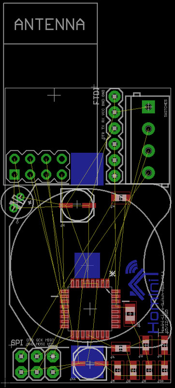
So that is why i looked at the idea of moving the cap out of the way to the other side of the board, putting the radio down onto the bottom of the board but keeping its orientation. I think this may reduce the thickness of the overall package slightly, will still be very tight (within 1mm i think), but a possibility it would fit (maybe). Shown in the design layout below. I think if i could remove the black plastic standoffs on the header for the radio and mount it practically touching the board itself then i may have a chance to get it in.
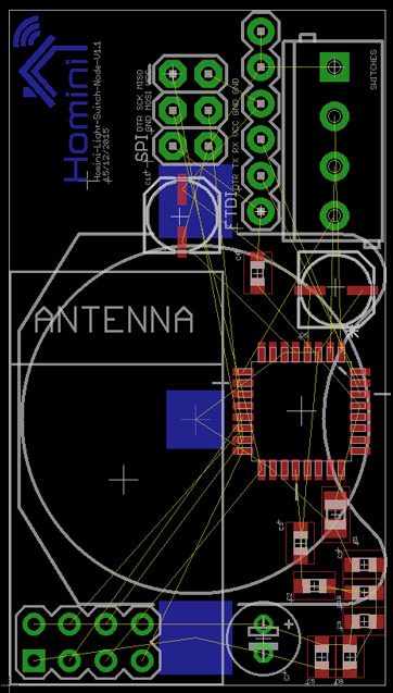
First of all, do you think that there would be any issues with the layout i have placed in the second design? As far as I can see i have done the main things like keeping the caps next to what they are intending to protect, kept under the radio board clean, have 1 x 100uF cap for spikes on radio and 2 47uF cap's for additional large spikes, 0.1uF caps are dotted around the bottom to reduce small spikes, managed to get a SPI and FTDI header included with all the resistors and caps needed.
The last few days I'm sitting at the stage of just rearranging the design to fit into my environment, I may have to change the backbox if needed but i would prefer to manufacture the board to fit into the smaller space if possible. but if physical limitations are there that is impossible to work around it would leave this as the only resort.
-
As the night draws to a close, it would appear i have found the physical sizing issue solution! Now, just for the routing to be done. Another stage, another day! As this project gets closer to a completed board, the more I get excited about the manufacturing of my first ever useful custom made PCB. After all, this is what a community built project is all about, experienced users helping armatures become experienced to help armatures, isn't it? I'd like to just take this post to thank everyone that assisted me so far with this project!
The remaining steps:
- Add MySensors' logo/branding to the board.
- Complete the routing of the board.
-
Good morning guys, just to keep the topic updated with the latest info on this project;
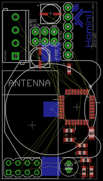
I'm still currently designing the board, trying to move parts around and route the traces. Because of everything being so cramped I'm having a real hard time getting this done. I'm having a couple of issues here where i can't get traces from certain points (top left corner) out and around the through-hole components so i will need to be moving some things around again, but I'm constantly pushed on a cramped space to physically get this into the light switch. One of the biggest issues i have is the terminal block, I may remove this and just end up soldering the switch cable directly to the board. The other issue i have is a software issue with eagle and ITead manufacturer, I'm creating routes with >8mil thickness (the website says that 6mil is minimum), then using their checking DRC file, and its throwing back errors relating to the trace width, however if i create the traces in 10mil its fine. However, there is just no way at all i can get away with 10mil :(
Today's agenda:
-
Remove screw terminals.
-
Relocate the micro controller under the nRF board, not under the antenna section though.
-
Relocate some of the components around the top of the board to allow traces through.
If i could get some feedback from you guys on the following, it would be appreciated.
-
Do you think I might be able to route/trace on the bottom layer under the antenna section (Antenna will be sitting about 2-5mm above the top layer) without receiving interference.
-
What do you think about my DRC Check errors? ITead say >6mil but i get errors on 8.5/9mil.
-
-
hi @samuel235 Check the rules spacing between traces. Trace width needs to be minimum 6 mil, but space between traces also has a minimum, maybe this is set higher ? I have used this DRU file and so far always had good boards from manufacturers.
Gert_Sanders.dru
Maybe this helps your tracing issue. -
hi @samuel235 Check the rules spacing between traces. Trace width needs to be minimum 6 mil, but space between traces also has a minimum, maybe this is set higher ? I have used this DRU file and so far always had good boards from manufacturers.
Gert_Sanders.dru
Maybe this helps your tracing issue.Good evening @GertSanders - There is nothing else on the board, I'm literally testing this on a clean board file, nothing on it at all. Just 1 wire. So there for there is essencially nothing to make a spacing issue around the wire. I have just tried to do it on any other layer than top or bottom and it doesn't create an error.... Is there any area of the DRC checks that only apply to the width of the top/bottom traces?
-
hi @samuel235 Beats me, if there is only 1 wire then maybe you have a conflict between the net class and the DRU. But I do not know what would be the issue without trying the same DRC check on your board file.
-
hi @samuel235 Beats me, if there is only 1 wire then maybe you have a conflict between the net class and the DRU. But I do not know what would be the issue without trying the same DRC check on your board file.
@GertSanders - I have just tried your DRU file, its doing it for that too.... Your minimum width and spacing is set to 6mil, i've ran my routes in 8 and 12.
EDIT: Turns out you were correct in advising the net class conflict, i went into the net class editor and it is set to 12mil so i changed this to 6 to double check, and it works perfectly. Can i leave this at 6 without any issues or is it there for a specific reason? I'm going to have a little research on these net classes because i honestly don't understand their purpose when they are set to a value above that of a custom DRC check.
-
hi @samuel235 The netclasses allow you to differentiate trace widths and spacing automatically when using the autorouter. If you do nothing, then all traces are routed by the autorouter according to the DRU. In the Netclasses you can overrule the default trace width and spacing to be respected by the autorouter.
When you check a trace (checking it's attributes) you can see to which net class it belongs. It is mentioned at the bottom.
Why different netclasses ? For example if you use power lines on your board, you could want them to be wider and have more clearance from other wires. To be able to check that the extra clearance is respected, you can define extra clearance in a net class called "power" and then make those wirelines for the power net member of the net class "power". If you use the autorouter, and you defined a width of 20mil for the power net, then the autorouter will make those traces 20mil wide. If you defined a clearance of 15mil for the power net, then all traces different from that power net need to be routed at least 15mil away from the power trace (e.g. Vcc signal or GND signal). If you trace by hand, then sometimes one could be tracing a signal line too close to a power line, and when doing a design rule check, the net class limitations are taken into account.
@GertSanders I think I explained incorrectly, i understand that the net classes are for the autorouter and how you can tell the auto route to do different classes for different instances. But what i don't understand is why if i have manually routed everything, why is the drc checker using the values on net classes, is it just as simple as changing the net classes to the board houses specific requirements?
Also, would there be a way to create different profiles for the net classes for each board house, just like how you can create different drc files for different needs?
-
@samuel235 If a DRU file species that two signals need to be a minimum of 6mil apart and the net class requires that different signals need to be 8mil apart, then the larger spacing is what counts. If your default net class has a larger spacing minimum then the DRC of a board house, then you need to follow the net class definition when doing manual routing. Autorouting takes into account the most stringent requirement automatically.
You can have several DRU files, but I do not know if you can link them to specific netclasses.