In wall light switch node - Custom PCB
-
hi @samuel235 The netclasses allow you to differentiate trace widths and spacing automatically when using the autorouter. If you do nothing, then all traces are routed by the autorouter according to the DRU. In the Netclasses you can overrule the default trace width and spacing to be respected by the autorouter.
When you check a trace (checking it's attributes) you can see to which net class it belongs. It is mentioned at the bottom.
Why different netclasses ? For example if you use power lines on your board, you could want them to be wider and have more clearance from other wires. To be able to check that the extra clearance is respected, you can define extra clearance in a net class called "power" and then make those wirelines for the power net member of the net class "power". If you use the autorouter, and you defined a width of 20mil for the power net, then the autorouter will make those traces 20mil wide. If you defined a clearance of 15mil for the power net, then all traces different from that power net need to be routed at least 15mil away from the power trace (e.g. Vcc signal or GND signal). If you trace by hand, then sometimes one could be tracing a signal line too close to a power line, and when doing a design rule check, the net class limitations are taken into account.
@GertSanders I think I explained incorrectly, i understand that the net classes are for the autorouter and how you can tell the auto route to do different classes for different instances. But what i don't understand is why if i have manually routed everything, why is the drc checker using the values on net classes, is it just as simple as changing the net classes to the board houses specific requirements?
Also, would there be a way to create different profiles for the net classes for each board house, just like how you can create different drc files for different needs?
-
@samuel235 If a DRU file species that two signals need to be a minimum of 6mil apart and the net class requires that different signals need to be 8mil apart, then the larger spacing is what counts. If your default net class has a larger spacing minimum then the DRC of a board house, then you need to follow the net class definition when doing manual routing. Autorouting takes into account the most stringent requirement automatically.
You can have several DRU files, but I do not know if you can link them to specific netclasses.
@GertSanders Ahh okay, that makes complete sense now. So the default is set to Width: 10mil, Drill: 20mil, Clearance: 10mil. ITead specify Width: 8mil, Drill: 0.3mm, Clearance: 8mil, I took these figures from here.
So I am safe to change my net classes to those of the board house to run the checks and then revert them back once i generate my gerber files? Or have i miss understood?
-
@samuel235 You can change the defaults to the values of the boardhouse and leave it at that. When generating the GERBER files, the DRU or net class values are no longer important. You only need the values when checking against design rules.
-
@samuel235 You can change the defaults to the values of the boardhouse and leave it at that. When generating the GERBER files, the DRU or net class values are no longer important. You only need the values when checking against design rules.
@GertSanders said:
@samuel235 You can change the defaults to the values of the boardhouse and leave it at that. When generating the GERBER files, the DRU or net class values are no longer important. You only need the values when checking against design rules.
Awesome! I shall get it checked and posted here in a minute and hopefully I'll get it ordered tonight :)
-
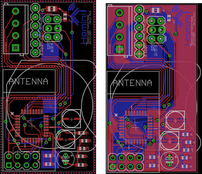
And the final designs are shown below. As you can see the one on the left is without the ground planes and the one on the right is with them. If anything is jumping out in terms of errors or discrepancies, please don't hold back, let me know ;)
-
UPDATE!
Just a little update to keep you all posted; I have sent my Gerber files off, they have been confirmed to be of the correct format and my boards are now being produced. I ordered the parts last night, enough for backups/errors, soon as everything arrives i will get this made up and give you another update on the situation of the board. The only thing i wasn't comfortable with was the price of the screw terminal and the fact i used a through hole capacitor for the 100uF (C7). The next revision of the board i will be using a surface mount 100uF capacitor for this, now i managed to find it. The terminal for the switches, I'm looking at maybe having a crimped push connector on the switch that just slots onto some sort of header pin on the board instead of a screw terminal.
Either way, Homini Light Switch Node Version 1.1 Revision 1 is on its way!
-
I have just received confirmation that the board house has released the PCB's. Lets see how long these take to get here! Itching to get this module on the move again. I will be back soon as they get here, don't go anywhere!
-
UPDATE!
I have just received all components for the boards, we're just waiting on the boards themselves to arrive from ITead Studios.
Time to get this project moving!
-
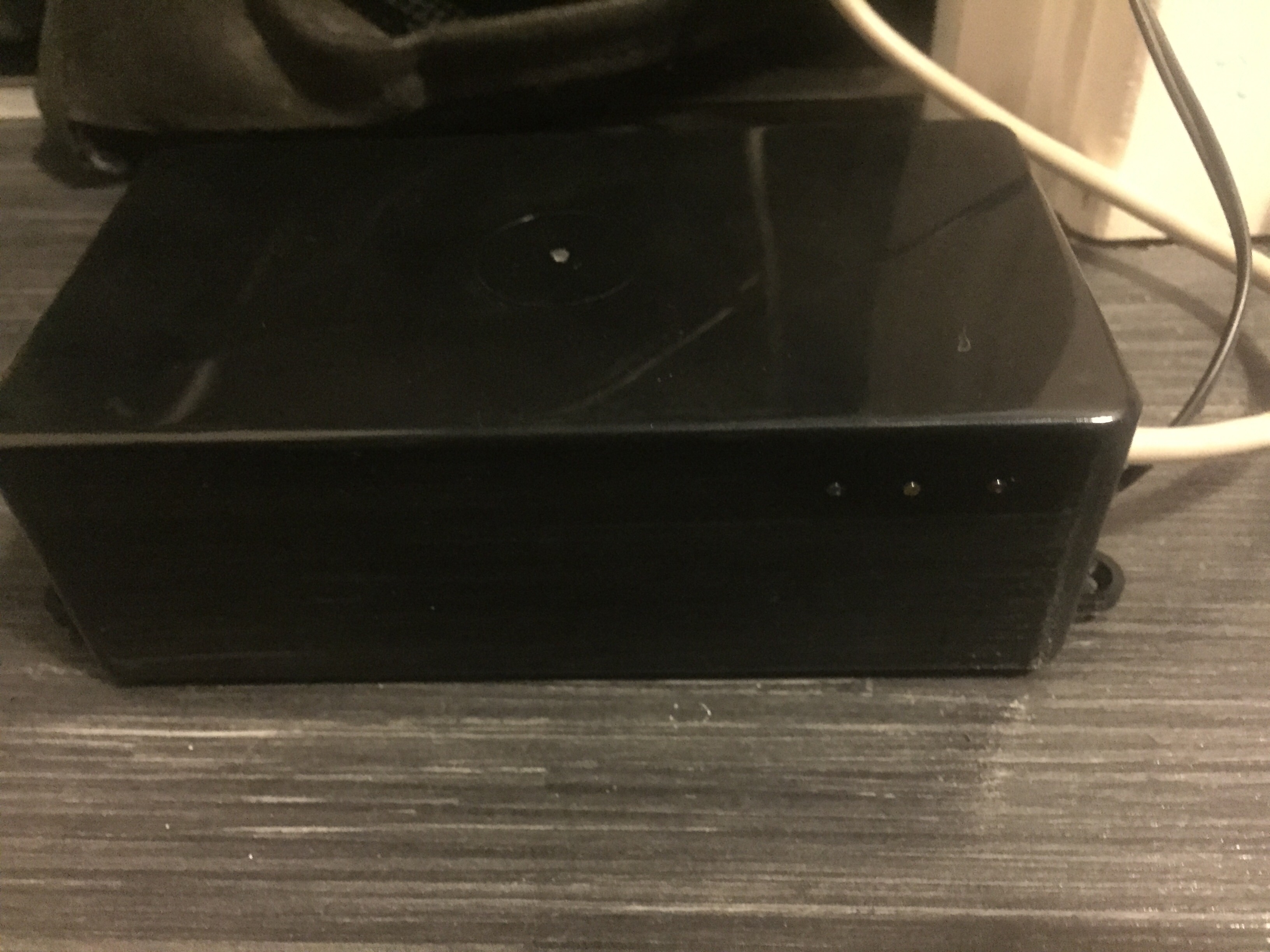
While waiting for my boards to arrive i decided to create a housing for my gateway including flashing status LEDs. Its in no means a finished product, but i feel its enough to house the gateway components while i'm building my network to save any incidents destroying the parts. Within the next few days i will get a guide up with images and maybe a video of the LEDs and their function up on a hardware guide topic.
-
So then, we have another update!
UPDATE!
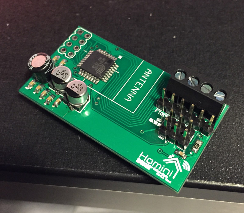
The boards ave arrived safe and sound, i have populated one of them with everything apart from the nRF module. So, its time to get the bootloader burnt. This is the daunting task for me, i have no idea what i am doing here, so if you guys feel like you could give me some helpful pointers in the right direction I would really appreciate all the help you can offer.
-
Hi! Depending on which bootloader you want, but why not go with the MySensors with OTA updates by tekka?
http://forum.mysensors.org/topic/838/windows-gui-controller-for-mysensors/75If you want the original arduino bootloader: https://www.arduino.cc/en/Hacking/Bootloader?from=Tutorial.Bootloader
-
Hi! Depending on which bootloader you want, but why not go with the MySensors with OTA updates by tekka?
http://forum.mysensors.org/topic/838/windows-gui-controller-for-mysensors/75If you want the original arduino bootloader: https://www.arduino.cc/en/Hacking/Bootloader?from=Tutorial.Bootloader
@sundberg84 - I was reading that exact post from tekka as you posted this. However, i'm probing around on my board and found for some reason my 3v line is 0.24v. So I have to do some investigation work on that this morning. Hoping the bootloader will be a piece of cake once the hardware is working as should be.
-
Hi! Depending on which bootloader you want, but why not go with the MySensors with OTA updates by tekka?
http://forum.mysensors.org/topic/838/windows-gui-controller-for-mysensors/75If you want the original arduino bootloader: https://www.arduino.cc/en/Hacking/Bootloader?from=Tutorial.Bootloader
@sundberg84 So i have my hardware issue corrected now. Am i reading Tekka's instructions correctly, this new board is to be connected through serial to my gateway and then programmed essentially by the gateway through MYSController which is connected to my gateway via ethernet? Does that sound correct?
-
No, i would recommend you have a look at some youtube tutorials. Im not familiar with programming through the ISP headers which i think you should do. I use a seperate arudino uno as ISP programmer.
-
@samuel235: cool. happy for you.
first you need to burn the bootlader in your atmel 328p. When it comes as ic-only, factory setting is 1mhz internal rc. and there is no bootloader yet. So you can't use ftdi at this moment, nor ota. So you need to burn the bootloader with avrspi. Like @sundberg84 said you can use the "arduino uno as isp programmer" method if you have an uno..On my side, I don't use this method, I prefer to use an usbasp. But both method works well.
When burning bootloader, you will need to set fuses too, corrsponding to the bootloader.Sorry, I have not much time to make an howto, just point you in some direction..i hope it helps a little bit.
Edit: you can find some howto here http://www.gammon.com.au/breadboard
@scalz I'm using a USBasp programmer, however i think i may have an issue with my reset pin. I have continuity on every other ISP header pin and the associated pin on the ATMega but not the reset pin. Is this normal, should i be seeing continuity between ISP RESET and pin 29 on the ATMega?
-
I think you should have continuity between avrspi connector RST pin and your atmega RST pin...don't see why not. Have you checked your routing? I think so...Maybe a bad solder on this pin???
-
I think you should have continuity between avrspi connector RST pin and your atmega RST pin...don't see why not. Have you checked your routing? I think so...Maybe a bad solder on this pin???
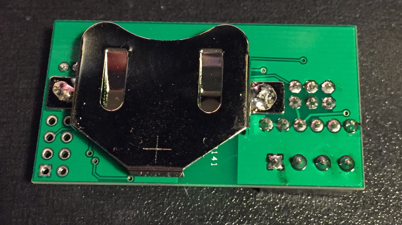
@scalz I may have found the problem, i have just completed a x25 magnification inspection on the boards and every board has atleast one filled VIA. I'm going to get a makeshift jumper in place on this board and test for continuity again.
I get continuity from the pin to the one side of the capacitor but nothing from the MEGA to the pin, it feels like the capacitor is stopping it coming through...
Hello! It looks like you're interested in this conversation, but you don't have an account yet.
Getting fed up of having to scroll through the same posts each visit? When you register for an account, you'll always come back to exactly where you were before, and choose to be notified of new replies (either via email, or push notification). You'll also be able to save bookmarks and upvote posts to show your appreciation to other community members.
With your input, this post could be even better 💗
Register Login