Error flashing bootloader to atmega328p au board I design
-
Hi
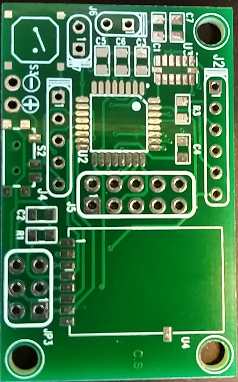
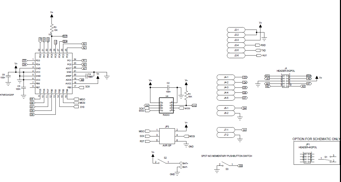
I design this board (schematic and pcb pics):
I bought atmega328p au from here:
link text
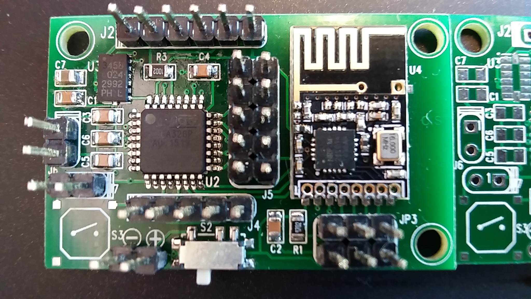
I solder all components and check and everything seems connected right.
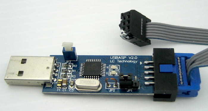
Then I tried to programme the chip with bootloader(as you see in the pics there is spi connector) using USBASP V2.0:
I added to boards.txt the following section:##############################################################
int.name=Arduino int
int.upload.tool=avrdude
int.upload.protocol=arduinoint.bootloader.tool=avrdude
int.bootloader.unlock_bits=0x3F
int.bootloader.lock_bits=0x0Fint.build.board=AVR_PRO
int.build.core=arduino
int.build.variant=eightanaloginputsArduino int internal clock (3.3V, 8 MHz) w/ ATmega328
--------------------------------------------------
int.menu.cpu.8MHzatmega328=ATmega328 (3.3V, 8 MHz)
int.menu.cpu.8MHzatmega328.upload.maximum_size=30720
int.menu.cpu.8MHzatmega328.upload.maximum_data_size=2048
int.menu.cpu.8MHzatmega328.upload.speed=57600int.menu.cpu.8MHzatmega328.bootloader.low_fuses=0xE2
int.menu.cpu.8MHzatmega328.bootloader.high_fuses=0xDA
int.menu.cpu.8MHzatmega328.bootloader.extended_fuses=0x05
int.menu.cpu.8MHzatmega328.bootloader.file=atmega/ATmegaBOOT_168_atmega328_pro_8MHz.hexint.menu.cpu.8MHzatmega328.build.mcu=atmega328p
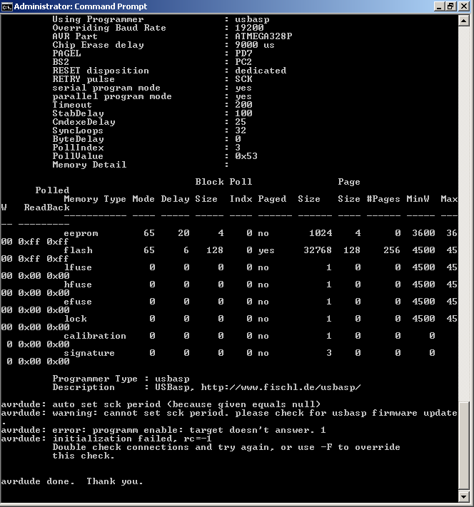
int.menu.cpu.8MHzatmega328.build.f_cpu=8000000Land from Arduino IDE I tried to burn bootloader and got this output:
avrdude: Version 6.0.1, compiled on Apr 15 2015 at 19:59:58
     Copyright (c) 2000-2005 Brian Dean, http://www.bdmicro.com/
     Copyright (c) 2007-2009 Joerg Wunsch

     System wide configuration file is "C:\Program Files (x86)\Arduino\hardware\tools\avr/etc/avrdude.conf"

     Using Port                    : usb
     Using Programmer              : usbasp
     AVR Part                      : ATmega328P
     Chip Erase delay              : 9000 us
     PAGEL                         : PD7
     BS2                           : PC2
     RESET disposition             : dedicated
     RETRY pulse                   : SCK
     serial program mode           : yes
     parallel program mode         : yes
     Timeout                       : 200
     StabDelay                     : 100
     CmdexeDelay                   : 25
     SyncLoops                     : 32
     ByteDelay                     : 0
     PollIndex                     : 3
     PollValue                     : 0x53
     Memory Detail                 :

                              Block Poll               Page                       Polled
       Memory Type Mode Delay Size  Indx Paged  Size   Size #Pages MinW  MaxW   ReadBack
       ----------- ---- ----- ----- ---- ------ ------ ---- ------ ----- ----- ---------
       eeprom        65    20     4    0 no       1024    4      0  3600  3600 0xff 0xff
       flash         65     6   128    0 yes     32768  128    256  4500  4500 0xff 0xff
       lfuse          0     0     0    0 no          1    0      0  4500  4500 0x00 0x00
       hfuse          0     0     0    0 no          1    0      0  4500  4500 0x00 0x00
       efuse          0     0     0    0 no          1    0      0  4500  4500 0x00 0x00
       lock           0     0     0    0 no          1    0      0  4500  4500 0x00 0x00
       calibration    0     0     0    0 no          1    0      0     0     0 0x00 0x00
       signature      0     0     0    0 no          3    0      0     0     0 0x00 0x00

     Programmer Type : usbasp
     Description     : USBasp, http://www.fischl.de/usbasp/

avrdude: auto set sck period (because given equals null)
avrdude: warning: cannot set sck period. please check for usbasp firmware update.
avrdude: error: programm enable: target doesn't answer. 1
avrdude: initialization failed, rc=-1
         Double check connections and try again, or use -F to override
     this check.


avrdude done.  Thank you.

Error while burning bootloader.
Am I at the right direction and should focus on checking my soldering or I burning firmware the wrong way?
the chip is without any bootloader and I don't know what is his "factory" state. also I want to drive this board without an external clock and only with internal 8mhz clock (does the boards.txt fit to this?)I will be happy to have some help here because I banging my head on this for days...
-
@Mickey Nice board ! Just a question: why did you add the 56K (R1) ?
The schematic does not show U3, is the schematic complete ? -
hi.
the factory state for chip is Internal RC 1Mhz. So be careful, when you set the fuses to not set External fuses ON if you have no crystal onboard. because you will need one then ;)
Did you program the fuses with avrdude or avrdudess? and then upload your bootloader with arduino ide...or do you try to change fuses with arduino ide? -
hi.
the factory state for chip is Internal RC 1Mhz. So be careful, when you set the fuses to not set External fuses ON if you have no crystal onboard. because you will need one then ;)
Did you program the fuses with avrdude or avrdudess? and then upload your bootloader with arduino ide...or do you try to change fuses with arduino ide?@scalz said:
hi.
the factory state for chip is Internal RC 1Mhz. So be careful, when you set the fuses to not set External fuses ON if you have no crystal onboard. because you will need one then ;)
Did you program the fuses with avrdude or avrdudess? and then upload your bootloader with arduino ide...or do you try to change fuses with arduino ide?The only thing I tried is what I wrote. I didnt try to mess with fuses. Isnt boards.txt implies that the fuses changed also by trying to bootloader burn?
Any way if I want to program this chip what are the fuses state to change? I would like 8mhz internal... -
@Mickey Nice board ! Just a question: why did you add the 56K (R1) ?
The schematic does not show U3, is the schematic complete ?@GertSanders said:
@Mickey Nice board ! Just a question: why did you add the 56K (R1) ?
The schematic does not show U3, is the schematic complete ?U3 is not relevant to topic but yes the schematic is short u3 which is ADXL345
Also I used 56k because I didnt find 47k in my stock...(is it a problem?) -
@Mickey I'm just wondering why you would need a pull up of 56K, since the internal pullup resistor of those pins in the atmega328 is about the same value (somewhere between 30K and 50K according to datasheet). I see no need for R1.
-
@Mickey I'm just wondering why you would need a pull up of 56K, since the internal pullup resistor of those pins in the atmega328 is about the same value (somewhere between 30K and 50K according to datasheet). I see no need for R1.
@GertSanders said:
@Mickey I'm just wondering why you would need a pull up of 56K, since the internal pullup resistor of those pins in the atmega328 is about the same value (somewhere between 30K and 50K according to datasheet). I see no need to R1.
When I design the board I use the sensebender micro as reference. I did ask my self is it really needed but Deside to go with that but its not part of the problem...
-
@Mickey Correct, if electrically your board is OK, and you do not have a spare working Arduino board, you will need to use an AVR programmer to flash the bootloader.
-
@Mickey Correct, if electrically your board is OK, and you do not have a spare working Arduino board, you will need to use an AVR programmer to flash the bootloader.
@GertSanders said:
@Mickey Correct, if electrically your board is OK, and you do not have a spare working Arduino board, you will need to use an AVR programmer to flash the bootloader.
What is correct? I use an Avr programmer - Usbasp as I mention . I have a few working arduinos is it better to use them as a programmer? Can you tell me what values should I need to the fueses?
-
@Mickey As I do not have a AVR programmer, I flash my processors with my old Arduino. The fuses I use are the same I have in one of the earlier messages.
For me, the easiest way to work was to extend the sketch made by GAMMON (Atmega_Board_Programmer), but how I changed that sketch is a bit complicated to explain in a mail. I basically converted my bootloader HEX file into an ascii string, which I added in a '.h' file to his sketch. Then I hacked his code so that when I choose atmega328 I get my boatloader, instead of the default.
GAMMON's sketch also reprograms the fuses.
In his sketch I started with this change:
//#define USE_ATMEGA168 true
//#define USE_ATMEGA328P_8M true
#define USE_ATMEGA328P_8Mi true
//#define USE_ATMEGA328P trueanother piece of code I changed was this:
// ATmega328P
{ { 0x1E, 0x95, 0x0F },
0x7E00, // start address
#if USE_ATMEGA328P_8Mi
optiboot_atmega328_8Mhz_B0_hex, // loader image
sizeof optiboot_atmega328_8Mhz_B0_hex,
// 0xE2, // fuse low byte: internal clock, max start-up time
0xFF, // fuse low byte: external clock, max start-up time
0xDE, // fuse high byte: SPI enable, boot into bootloader, 512 byte bootloader
0x07, // fuse extended byte: brown-out detection off
#else
atmega328_optiboot,
sizeof atmega328_optiboot,
0xFF, // fuse low byte: external clock, max start-up time
0xDE, // fuse high byte: SPI enable, boot into bootloader, 512 byte bootloader
0x05, // fuse extended byte: brown-out detection at 2.7V
#endif
0x2F
}, // lock bits: SPM is not allowed to write to the Boot Loader section.I also added the attached '.h' file to his sketch:
optiboot_atmega328p_8M_B0.hFor me this is the fastest and most reliable way to flash my processors.
-
@Mickey: I think you have to change fuses. What I usually do is:
- program fuses with : avrdudess+usbasp.
you can check your fuse here: http://www.engbedded.com/fusecalc/ - Then copy atmega boards files, and you can use arduino ide to upload your bootloader, still with usbasp of course.
- Finally, you can bootload with ftdi.
But, adding atmega board files doesn't reprogram the fuses if I remember right. If it doesn't work like I explained, then maybe hardware connection..
On my side, I prefer usbasp/avrspi. it's very easy too, I think :smiley: most important is that it works :wink:
- program fuses with : avrdudess+usbasp.
-
@Mickey: I think you have to change fuses. What I usually do is:
- program fuses with : avrdudess+usbasp.
you can check your fuse here: http://www.engbedded.com/fusecalc/ - Then copy atmega boards files, and you can use arduino ide to upload your bootloader, still with usbasp of course.
- Finally, you can bootload with ftdi.
But, adding atmega board files doesn't reprogram the fuses if I remember right. If it doesn't work like I explained, then maybe hardware connection..
On my side, I prefer usbasp/avrspi. it's very easy too, I think :smiley: most important is that it works :wink:
@scalz said:
@Mickey: I think you have to change fuses. What I usually do is:
- program fuses with : avrdudess+usbasp.
you can check your fuse here: http://www.engbedded.com/fusecalc/ - Then copy atmega boards files, and you can use arduino ide to upload your bootloader, still with usbasp of course.
- Finally, you can bootload with ftdi.
But, adding atmega board files doesn't reprogram the fuses if I remember right. If it doesn't work like I explained, then maybe hardware connection..
On my side, I prefer usbasp/avrspi. it's very easy too, I think :smiley: most important is that it works :wink:
Hi
How can I change fuses if the avr programmer doesn't even detect the chip? when I runavrdude -b 19200 -c usbasp -p m328p -vI get
- program fuses with : avrdudess+usbasp.
-
Double check the connections. If the programmer does not see your processor, there is not much more that can be done on the software side. First check hardware again.
-
@scalz said:
@Mickey: I think you have to change fuses. What I usually do is:
- program fuses with : avrdudess+usbasp.
you can check your fuse here: http://www.engbedded.com/fusecalc/ - Then copy atmega boards files, and you can use arduino ide to upload your bootloader, still with usbasp of course.
- Finally, you can bootload with ftdi.
But, adding atmega board files doesn't reprogram the fuses if I remember right. If it doesn't work like I explained, then maybe hardware connection..
On my side, I prefer usbasp/avrspi. it's very easy too, I think :smiley: most important is that it works :wink:
Hi
How can I change fuses if the avr programmer doesn't even detect the chip? when I runavrdude -b 19200 -c usbasp -p m328p -vI get
- program fuses with : avrdudess+usbasp.
-
@Mickey Maybe you need to disconnect the radio. I am not able to use SPI programming with the radio connected...
@AWI said:
@Mickey Maybe you need to disconnect the radio. I am not able to use SPI programming with the radio connected...
I also thought that but I made another board without the radio with the same error.
I needed a fast way to figure it out so I desolder the atmega from an old arduino nano board but before I did it I read the fuses and got this:
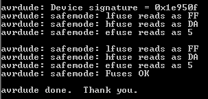
then I soldered the virgin series I have and read the fuses:
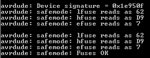
so first of all It appears that I need the chips first hook up to an external clock just to be able to read the fuses and then change them.
Hello! It looks like you're interested in this conversation, but you don't have an account yet.
Getting fed up of having to scroll through the same posts each visit? When you register for an account, you'll always come back to exactly where you were before, and choose to be notified of new replies (either via email, or push notification). You'll also be able to save bookmarks and upvote posts to show your appreciation to other community members.
With your input, this post could be even better 💗
Register Login