2 channel in wall dimmer
-
@ahmedadelhosni Going slowly at the moment had to do a respin on my thermostat project as i have made some small errors. Some of the design is the same so i will verify some things on the other design. Also waiting for chinese new years to end
@Denke Yeah the holiday takes a long period there :)
Actually yesterday I read a lot about AC-DC converters and really learned new things, but I may need your help in clarifying some points please. I watched this video which guided me to this type of circuit design. Modlet Smart-Outlet Teardown and Review - (IT'S A POS)
Be aware that by this type of design with the transformer less design considerations needs to be taken when connecting computers and other stuff.
1- What I learned yesterday is that a "transformless" design is not safe ( don't know to what level of safety though ), but I read that there is no isolation between Main inputs and low voltage.
My questions:- Is this normal ? Would that affect the Atmega and other components ?
- How to avoid this ?
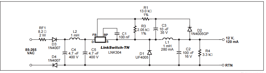
2- The above video mentioned that the Modlet outlet uses LNK304DN Datasheetwith outputs 12V. The below picture is from the datasheet and that reference was even used in the Modlet outlet as mentioned in the video.
My question:
- There are different designs in the datasheet but I can't diffrentiate between them and what is the best to use, but in all cases, this design still lacks the safety procedures, correct ? Like there is no MOV, Fuse .. ? It is just the circuit to produce a 12V 120mA which shall be stable and not noisy. Correct ?
3-
The AC is on the left hand side. the 0.33 uF capacitor in series on the 240 sets the maximum current, which should be around 10 mA on the AC side
I then changed some parts as the transformerless design would in simulation not give more than 10mA so I added the MAX 17552 circuit in between and set the input voltage to 24 V with the zener diode and by that I will be able to draw about 30 mA (starting current of the circuit that I tested is around 24 mA).
Can you explain what the 0.33 uF does to set the maximun current ?- What is the maximum current and how was it calculated ?
- How can I increase the output current to 100mA 5v/3.3v ?
- Actually the schematic is not clear at all when I download the pictuers. Maybe resolution :)
Thanks a lot for your support.
-
@Denke Very nice project! Hope to see a working protype soon. Any thoughts about making a relay switch based on this design. Will there be space and power for a 10A relay?
-
@Denke Yeah the holiday takes a long period there :)
Actually yesterday I read a lot about AC-DC converters and really learned new things, but I may need your help in clarifying some points please. I watched this video which guided me to this type of circuit design. Modlet Smart-Outlet Teardown and Review - (IT'S A POS)
Be aware that by this type of design with the transformer less design considerations needs to be taken when connecting computers and other stuff.
1- What I learned yesterday is that a "transformless" design is not safe ( don't know to what level of safety though ), but I read that there is no isolation between Main inputs and low voltage.
My questions:- Is this normal ? Would that affect the Atmega and other components ?
- How to avoid this ?
2- The above video mentioned that the Modlet outlet uses LNK304DN Datasheetwith outputs 12V. The below picture is from the datasheet and that reference was even used in the Modlet outlet as mentioned in the video.
My question:
- There are different designs in the datasheet but I can't diffrentiate between them and what is the best to use, but in all cases, this design still lacks the safety procedures, correct ? Like there is no MOV, Fuse .. ? It is just the circuit to produce a 12V 120mA which shall be stable and not noisy. Correct ?
3-
The AC is on the left hand side. the 0.33 uF capacitor in series on the 240 sets the maximum current, which should be around 10 mA on the AC side
I then changed some parts as the transformerless design would in simulation not give more than 10mA so I added the MAX 17552 circuit in between and set the input voltage to 24 V with the zener diode and by that I will be able to draw about 30 mA (starting current of the circuit that I tested is around 24 mA).
Can you explain what the 0.33 uF does to set the maximun current ?- What is the maximum current and how was it calculated ?
- How can I increase the output current to 100mA 5v/3.3v ?
- Actually the schematic is not clear at all when I download the pictuers. Maybe resolution :)
Thanks a lot for your support.
@ahmedadelhosni said:
My questions:
- Is this normal ? Would that affect the Atmega and other components ?
- How to avoid this ?
This is a matter of reference. When you have a power source with no contact to any othe rreference you are safe to touche one contact of that power source. If you make contact to the other one, you would be a resistor to the power source and act as esistor, having current runningthrough your body with all the negative impacts, including chance of death.
As explained, that is a matter of the reference. When you use a transformator, where secondary is not connected to anything else, you could safely make contact. In case you use any transfromless design, everything is somehow connected to mains. You are connected to grounds, so touching anything would be dangerous. As long as you do not touch anything, you are safe.
In fact a lot of electronics is tranformless with enough and safe insulation around it, so that no contact to grounds is possible. It is not only affecting persnal health, but could also be a source of fire if there could leak any current to grounds or mains from that circuitry. That's the reaosn for the insulation.In fact this applies to transformators as well, as the primay side has contact to grounds.
So, it does not affect any Atmel or so, it just raises the level of security precautions you have to take care of for this type of circuitry.
-
@ahmedadelhosni said:
My questions:
- Is this normal ? Would that affect the Atmega and other components ?
- How to avoid this ?
This is a matter of reference. When you have a power source with no contact to any othe rreference you are safe to touche one contact of that power source. If you make contact to the other one, you would be a resistor to the power source and act as esistor, having current runningthrough your body with all the negative impacts, including chance of death.
As explained, that is a matter of the reference. When you use a transformator, where secondary is not connected to anything else, you could safely make contact. In case you use any transfromless design, everything is somehow connected to mains. You are connected to grounds, so touching anything would be dangerous. As long as you do not touch anything, you are safe.
In fact a lot of electronics is tranformless with enough and safe insulation around it, so that no contact to grounds is possible. It is not only affecting persnal health, but could also be a source of fire if there could leak any current to grounds or mains from that circuitry. That's the reaosn for the insulation.In fact this applies to transformators as well, as the primay side has contact to grounds.
So, it does not affect any Atmel or so, it just raises the level of security precautions you have to take care of for this type of circuitry.
@tante-ju
Thanks for great clarification.
So does this only happens when the device is pluged in the wall ? In other words, there are a bunch of capacitors and passive components in the low side which has rederence to main inputs ( that's what i understood ) so touching is damgerous while plugged. But if i unplugged the device, will it still contain charges which can kill me ?
Suppose this is a wall plug and I have both terminals of the plug free to be touch ofcourse. So will the charges disappate through the terminals and then to my body ? -
@ahmedadelhosni : I agree too. yes mostly inwall. and yes there still can be some capa charged.
for the difference in the schematic. Generally you can use the standard schematic in datasheet for simple things even if you have to add few components. But for things like transformerless, which is more tricky for instance, it is not sufficient. you have to add components around. I don't remember right as I have already looked at this (and have a bunch of lnk306 and tny in stock), there are more complete schematics in appnotes or in the datasheet. But footprint increase to have something more secure or more optimized (the reason why I choosed hilink finally, but in some case transformerless makes sense and insulating is mandatory!). There are online tools at powerintegrations, to calculate what is possible to do regarding value of component. -
Thanks Tante-ju and Scalz for helping out with the answer. This is why i stated that you need to treat the equipment as hot, becouse that you don't have control of the reference to ground. But as long as it stays "inwall" and you are using 230 V rated switches on the low voltage switch then the insulations shall be ok and safe. But as soon as you open up and work with it you need to treat is as hot.
-
Thank you all. I still want to know whether there will be charges also when I unplug it or not ?
I am giving the example of a wall plug because it can be plugged and unplungged several times and the terminals can be touched. -
Thank you all. I still want to know whether there will be charges also when I unplug it or not ?
I am giving the example of a wall plug because it can be plugged and unplungged several times and the terminals can be touched.@ahmedadelhosni That all has to do if you have some sort of bleeder. or something that uses the charge. So in my design on the secondary side (+5V) there is always something that consumes the current. On the primary side you can see that there is bleeder resistors in paralell with the capacitor. So it should be safe from that aspect
-
@ahmedadelhosni That all has to do if you have some sort of bleeder. or something that uses the charge. So in my design on the secondary side (+5V) there is always something that consumes the current. On the primary side you can see that there is bleeder resistors in paralell with the capacitor. So it should be safe from that aspect
@Denke yeah great. I understood now.
I am thinking of using LNK304 to produce 120mA max. Still trying to investigate how to layout the pcb design correctly from a safety prespective.
Thanks for support -
Boards are now ordered. Lets hope they will work fine. I have some doubts about EMI coming from the boards when dimming. So now it will be measure and correct if needed
-
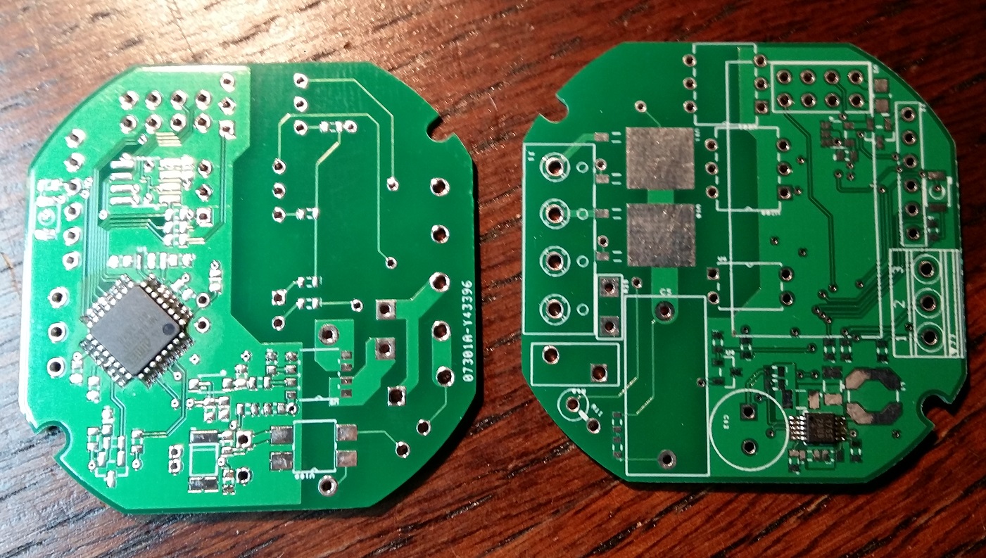
Finally new boards have arrived..
Assembly will start soon:)
![0_1458579519569_20160321_172537 [297989] (2).jpg](/uploads/files/1458579517358-20160321_172537-297989-2.jpg)
-
@Denke Nice :) I am really excited to see your results.
Regarding the resistor which is in parallel to act as a bleeder. What value do you think the most suitable ? 100K ? 1M ? and howa much watt ?Thanks.
-
@Denke Nice :) I am really excited to see your results.
Regarding the resistor which is in parallel to act as a bleeder. What value do you think the most suitable ? 100K ? 1M ? and howa much watt ?Thanks.
@ahmedadelhosni
Hi I have used 1M as bleeder in 0603 size. This resistor should be able to handle around 0.1W.If i have calculated right the power in the bleeder resistor should be around 0.05W
-
Any pictures of the assembled board ?
-
Any pictures of the assembled board ?
@ahmedadelhosni Have not started the assembly of these boards yet. Im currently doing assembly of my other project Wirsbo/Uponor thermostat replacement. And those boards seems to be fully functional.
I will post a picture as soon as I get it assembled
-
@ahmedadelhosni Have not started the assembly of these boards yet. Im currently doing assembly of my other project Wirsbo/Uponor thermostat replacement. And those boards seems to be fully functional.
I will post a picture as soon as I get it assembled
Thanks @Denke
-
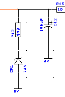
If I am not mistaken, isn't this the bleeding resistor in parallel with the cap ?
Why is there a reverse diode ? Won't this block the current from passing from the + terminal of the capacitor to the resistor then to gnd ? -
If I am not mistaken, isn't this the bleeding resistor in parallel with the cap ?
Why is there a reverse diode ? Won't this block the current from passing from the + terminal of the capacitor to the resistor then to gnd ?@ahmedadelhosni
It's a zener diode which will pass current once voltage is above 24v and then the resistor protects it from complete shorting to ground. -
First components added after a visit to the lab at work and some soldering under the microscope
Hello! It looks like you're interested in this conversation, but you don't have an account yet.
Getting fed up of having to scroll through the same posts each visit? When you register for an account, you'll always come back to exactly where you were before, and choose to be notified of new replies (either via email, or push notification). You'll also be able to save bookmarks and upvote posts to show your appreciation to other community members.
With your input, this post could be even better 💗
Register Login