💬 In Wall AC/DC Pcb for MySensors
-
Hi, just found your project and I believe it is a great job!
Please, I would like to try your project, but am unable to find alternative Aliexpress providers for the following material (because the provider does not deliver to my country) and cannot find any other provider for the same specs as:
- 10 x Zinc Oxide Varistor 250VAC 60J 2500A 10mm
Please, could you provide different providers to choose from or the specs to look for them?
Thank you very much and keep up the good work!
- 10 x Zinc Oxide Varistor 250VAC 60J 2500A 10mm
-
@fgallarday Did you check eBay? I ordered a pack these recently on the eBay
-
Hello @sunberg84
I went over the thread http://forum.mysensors.org/topic/1607/safe-in-wall-ac-to-dc-transformers, and came across your PCB - Great work!
Not sure how I can have the PCB made - I'd appreciate any pointers. I have looked in the Design Files section but couldn't make sense of the files.Thanks!
-
Hi @Sefi-Ninio!
You find a pcb manufacturer, check which gerber files they need and send them there in a zip/rar. I use Itead and they want these files in a .zipTop layer: pcbname.GTL
Bottom layer: pcbname.GBL
Solder Stop Mask top: pcbname.GTS
Solder Stop Mask Bottom: pcbname.GBS
Silk Top: pcbname.GTO
Silk Bottom: pcbname.GBO
NC Drill: pcbname.TXT
Outline layer: pcbname.DOThe files can be found if you download the project from openhardware.io.
But a small note - i am redesigning it some at the moment because the AC traces are to close to each other. This can make the board unsafe if its placed in a dirty or high humidity enviroment. I will update the files this week. Also note this is a test project - im no electrical engineer and learning as the project evolves - i cant garantee its safe.
-
Hi @sundberg84, really appreciate the quick reply!
Thanks for the explanation - I'll check Itead out.
Regarding the safety - I completely understand, but after reading all the 360+ posts in the thread, I gained confidence both in the HLK-PM01 as well as the general circuitry when using the fuses and varistor. I'm not electrical engineer as well, and learning as I go/read.Thanks again for the contribution, waiting for the 4th rev. ! :)
-
Great, I will try to release it tonight or tomorrow :)
Yea, i have a great confidence in the HLK as well, its my PCB and the AC traces i have learned more about and need to update.
-
Hi,
thanks for your great work..
great to have chosed a pwm output for the relay (ssr can be used as a dimmer)
but is it possible to add a fuse on the ssr output too ?thanks
-
Hi @vil1driver!
This pcb does not contain any relay. -
roh sry :D bad thread lol, i was think it was the http://forum.mysensors.org/topic/1540/110v-230v-ac-to-mysensors-pcb-board/72
too much windows opened =)
I can delete it if needed
-
Ok - updated to 3.1. Its mainly changes on the AC side to decrease risk of creepage and increase clearance.
See changes.txt for more detailed info.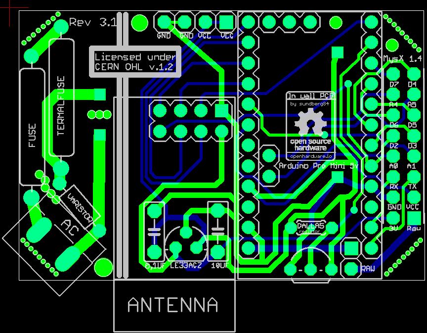
-
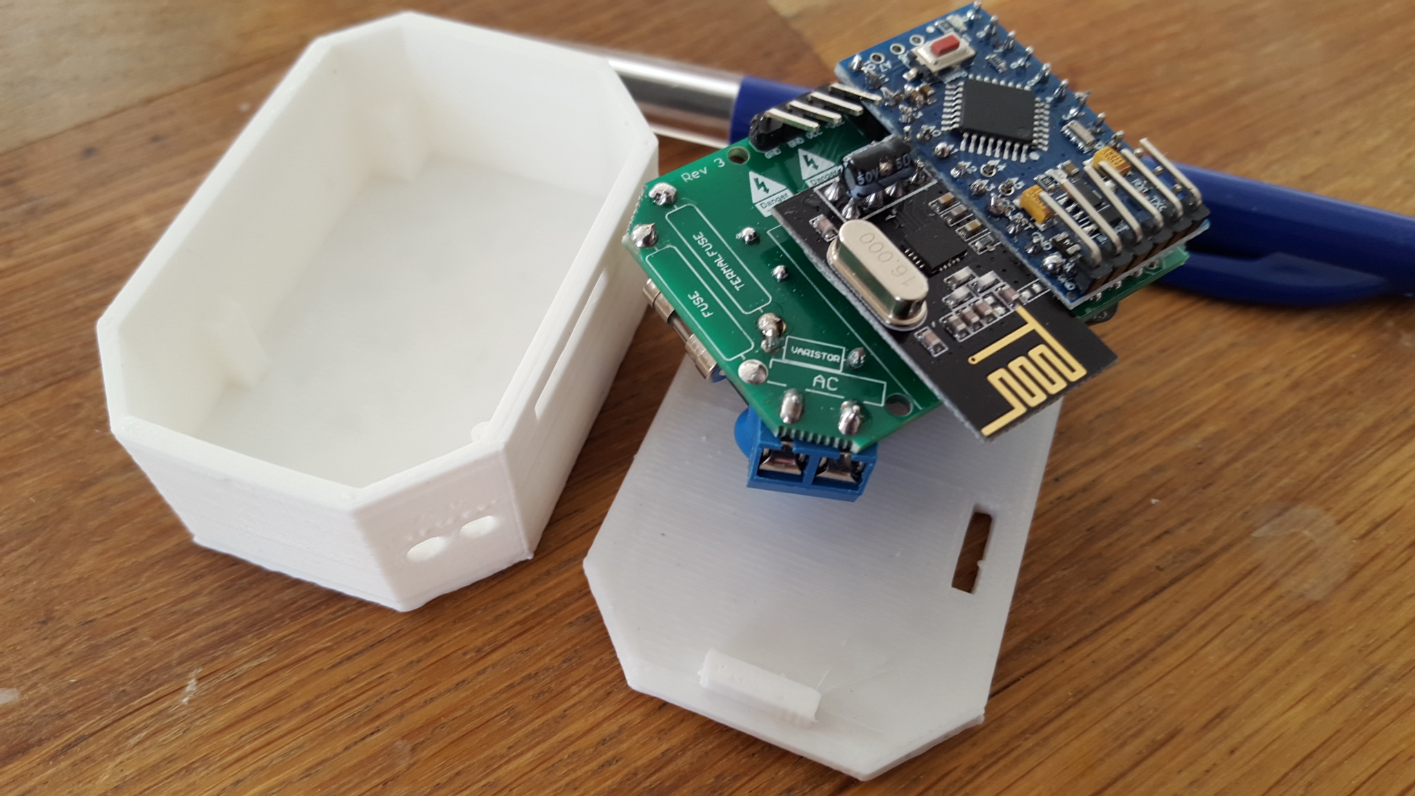
Playtime...
-
Sweeet!!!!
Say @sundberg84, have you considered also adding one or two relays to the mix?
I know it'll probably increase it's size footprint but in terms for height, if you position them next to the HLK unit then there shouldn't be a noticeable height increase. SSRs are very small. -
I have and might in the future... at the moment I'm focusing on safety, test and size. Rev 4 is ordered today with smd components. Let's see how that evolves first.
-
Hi @sundberg84,
I was talking with a friend of mine who has pcb design experience about your board, and he told me to tell you that it would be better to add creapage protection between the 220v and the 5v sections, by bigger distance at also a longated gap. He told me the term, but I can't remember it now... -
-
@Sefi-Ninio - Yea I should. Im working on Rev 4 and there is more creepage both between primary (220) and secondary (5) and also internally in primary. Everything is ordered but nothing recieved yet, but let me give you a small peak:
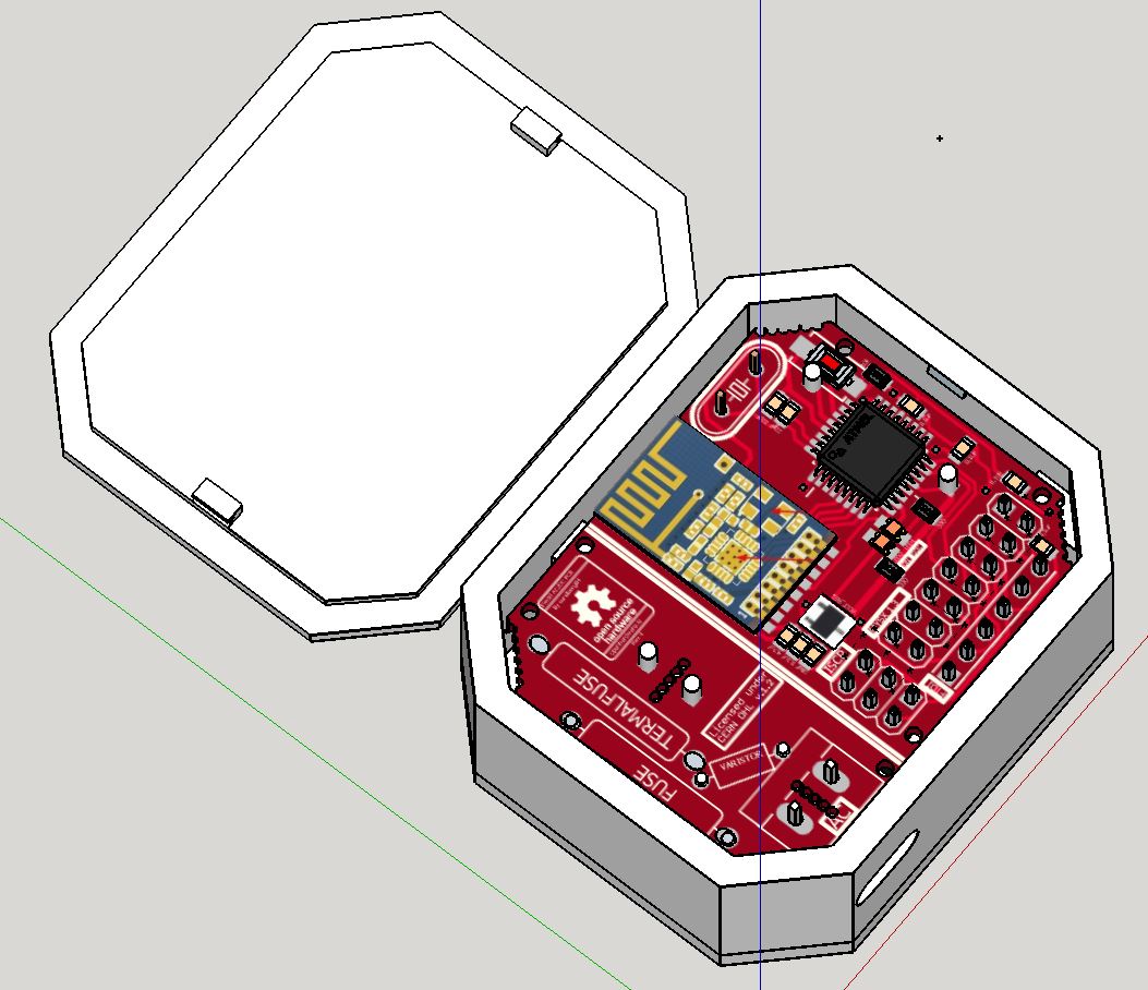
-
Looking good!
I see you went with the SMD path! did it allow for a smaller PCB?
Don't see how you handle the creepage though. -
Yes - smaller PCB.
Creepage is handled with:- Greater distance between components.
- Holes in PCB between components/parts that are close to each other.
Creepage distance is calculated here: http://creepage.com/