Battery percentage - Help needed
-
Your setup with 470k and 100k would make a quite good divider ratio for that Li battery range. Maybe increase both a little to limit leakage current.
BUT you can NOT use the readVcc() function here since battery isn't connected to Vcc. Instead you should replace it the normal code used with the voltage divider and analogRead() function. Can't guide you, but it should be like the standard example sketch for battery monitoring. This will give you more info. http://forum.mysensors.org/topic/2210/battery-sensor-measure-for-li-ion-cells
@m26872 Thank you for the pointer.
I used the sketch from the link, but still the readings are quite far off.I have tried checking the actual voltage at the division point. It reads 0.58V with a battery charge of 3.81V.
I my math doesn't fail me, it should be 0.69V...I then looked at the actual resistance of R1 and R2.
R1=1012e3
R2=220e3Of course this changes things, but not too drastically - now it should be 0.68V.
So I'm 15% wrong at my division point!Any suggestions?
I should add that the serial output vary a bit at first, but then settles in after 30 seconds or so. I guess that could be because the capacitor is a bit on the large size...
-
#include <SPI.h> #include <MySensor.h> #include <DHT.h> #define CHILD_ID_HUM 0 #define CHILD_ID_TEMP 1 #define HUMIDITY_SENSOR_DIGITAL_PIN 3 // define values for the battery measurement #define R1 1012e3 #define R2 220e3 #define VMIN 3.2 #define VMAX 4.2 #define ADC_PRECISION 1023 #define VREF 1.1 MySensor gw; DHT dht; unsigned long SLEEP_TIME = 5000; // Sleep time between reads (in milliseconds) float lastTemp; float lastHum; boolean metric = true; MyMessage msgHum(CHILD_ID_HUM, V_HUM); MyMessage msgTemp(CHILD_ID_TEMP, V_TEMP); int oldBatteryPcnt = 0; int BATTERY_SENSE_PIN = A0; void setup() { // use the 1.1 V internal reference analogReference(INTERNAL); gw.begin(); dht.setup(HUMIDITY_SENSOR_DIGITAL_PIN); // Send the Sketch Version Information to the Gateway gw.sendSketchInfo("Humidity", "1.0"); // Register all sensors to gw (they will be created as child devices) gw.present(CHILD_ID_HUM, S_HUM); gw.present(CHILD_ID_TEMP, S_TEMP); metric = gw.getConfig().isMetric; } void loop() { int batteryPcnt = getBatteryPercentage(); Serial.print("Battery percent: "); Serial.print(batteryPcnt); Serial.println(" %"); if (oldBatteryPcnt != batteryPcnt) { // Power up radio after sleep gw.sendBatteryLevel(batteryPcnt); oldBatteryPcnt = batteryPcnt; } // totally random test values gw.send(msgTemp.set(20, 1)); gw.send(msgHum.set(42, 1)); gw.sleep(SLEEP_TIME); //sleep a bit } int getBatteryPercentage() { // read analog pin value int inputValue = analogRead(BATTERY_SENSE_PIN); // calculate the max possible value and therefore the range and steps float voltageDividerFactor = (R1 + R2) / R2; float maxValue = voltageDividerFactor * VREF; float voltsPerBit = maxValue / ADC_PRECISION; float batteryVoltage = voltsPerBit * inputValue; float batteryPercentage = ((batteryVoltage-VMIN)/(VMAX-VMIN))*100; //int batteryPercentage = map(batteryVoltage, 0, maxValue, 0, 100); return batteryPercentage; } -
#include <SPI.h> #include <MySensor.h> #include <DHT.h> #define CHILD_ID_HUM 0 #define CHILD_ID_TEMP 1 #define HUMIDITY_SENSOR_DIGITAL_PIN 3 // define values for the battery measurement #define R1 1012e3 #define R2 220e3 #define VMIN 3.2 #define VMAX 4.2 #define ADC_PRECISION 1023 #define VREF 1.1 MySensor gw; DHT dht; unsigned long SLEEP_TIME = 5000; // Sleep time between reads (in milliseconds) float lastTemp; float lastHum; boolean metric = true; MyMessage msgHum(CHILD_ID_HUM, V_HUM); MyMessage msgTemp(CHILD_ID_TEMP, V_TEMP); int oldBatteryPcnt = 0; int BATTERY_SENSE_PIN = A0; void setup() { // use the 1.1 V internal reference analogReference(INTERNAL); gw.begin(); dht.setup(HUMIDITY_SENSOR_DIGITAL_PIN); // Send the Sketch Version Information to the Gateway gw.sendSketchInfo("Humidity", "1.0"); // Register all sensors to gw (they will be created as child devices) gw.present(CHILD_ID_HUM, S_HUM); gw.present(CHILD_ID_TEMP, S_TEMP); metric = gw.getConfig().isMetric; } void loop() { int batteryPcnt = getBatteryPercentage(); Serial.print("Battery percent: "); Serial.print(batteryPcnt); Serial.println(" %"); if (oldBatteryPcnt != batteryPcnt) { // Power up radio after sleep gw.sendBatteryLevel(batteryPcnt); oldBatteryPcnt = batteryPcnt; } // totally random test values gw.send(msgTemp.set(20, 1)); gw.send(msgHum.set(42, 1)); gw.sleep(SLEEP_TIME); //sleep a bit } int getBatteryPercentage() { // read analog pin value int inputValue = analogRead(BATTERY_SENSE_PIN); // calculate the max possible value and therefore the range and steps float voltageDividerFactor = (R1 + R2) / R2; float maxValue = voltageDividerFactor * VREF; float voltsPerBit = maxValue / ADC_PRECISION; float batteryVoltage = voltsPerBit * inputValue; float batteryPercentage = ((batteryVoltage-VMIN)/(VMAX-VMIN))*100; //int batteryPercentage = map(batteryVoltage, 0, maxValue, 0, 100); return batteryPercentage; }@ksga Can't see any error in your sketch. Sure you can add pinMode(BATTERY_SENSE_PIN, INPUT) but doubt it will matter.
So if you disconnect your divider from A0, the voltage at that divider point will raise to the right value?
-
@ksga Can't see any error in your sketch. Sure you can add pinMode(BATTERY_SENSE_PIN, INPUT) but doubt it will matter.
So if you disconnect your divider from A0, the voltage at that divider point will raise to the right value?
@m26872 I decided to trip everything from my breadboard and start over.
First thing - the voltage divider:
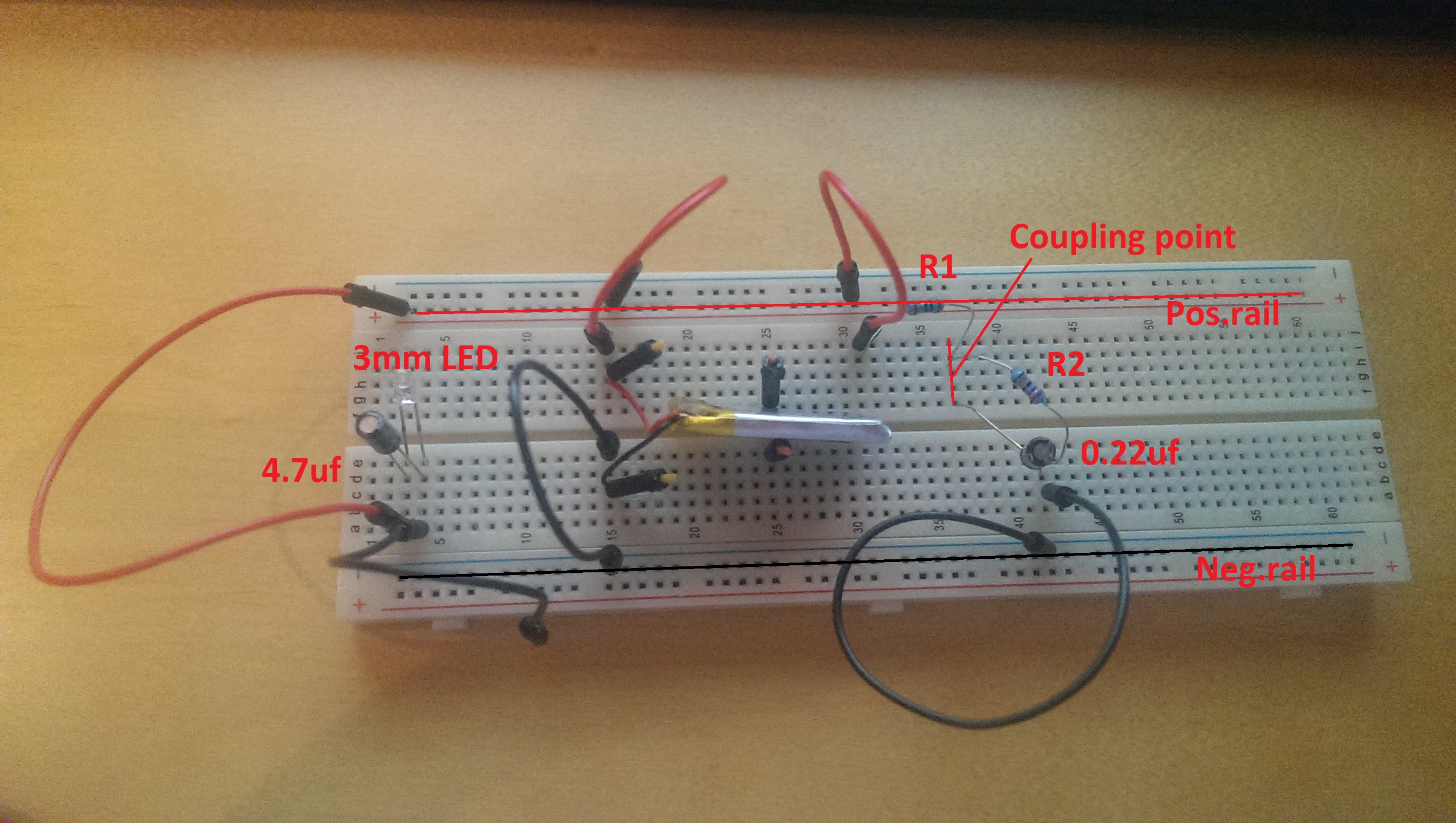
Simple Bat+ > pos.rail > R1 (1M, new specimen, verified resistance with multimeter) > R2(220k)/0.22uf capacitor > neg.rail > Bat-
In paralel I added an LED to put a bit of load on the battery for more realistic current.The results are:
Battery current: 4.03V
Neg.rail to coupling point R1-R2: 0.61V
Coupling point R1-R2 to Pos.rail: 2.78VDoes that make any sense?
I would expect 0.61V+2.78V=4.03V (or maybe I still haven't grasped the concept.)Hopefully this photo will make someone wiser than me point out my many mistakes ;-)

-
@m26872 I decided to trip everything from my breadboard and start over.
First thing - the voltage divider:
Simple Bat+ > pos.rail > R1 (1M, new specimen, verified resistance with multimeter) > R2(220k)/0.22uf capacitor > neg.rail > Bat-
In paralel I added an LED to put a bit of load on the battery for more realistic current.The results are:
Battery current: 4.03V
Neg.rail to coupling point R1-R2: 0.61V
Coupling point R1-R2 to Pos.rail: 2.78VDoes that make any sense?
I would expect 0.61V+2.78V=4.03V (or maybe I still haven't grasped the concept.)Hopefully this photo will make someone wiser than me point out my many mistakes ;-)

@ksga I can't see any current limiting resistor to the LED?
Start as simple as possible with few components. Short and few connections and wires to limit unexpected voltage drops in wires, breadboard or connections between. Remove the caps. -
@ksga I can't see any current limiting resistor to the LED?
Start as simple as possible with few components. Short and few connections and wires to limit unexpected voltage drops in wires, breadboard or connections between. Remove the caps.@m26872 Thank you for sticking with me.. I'm quite puzzled by this.
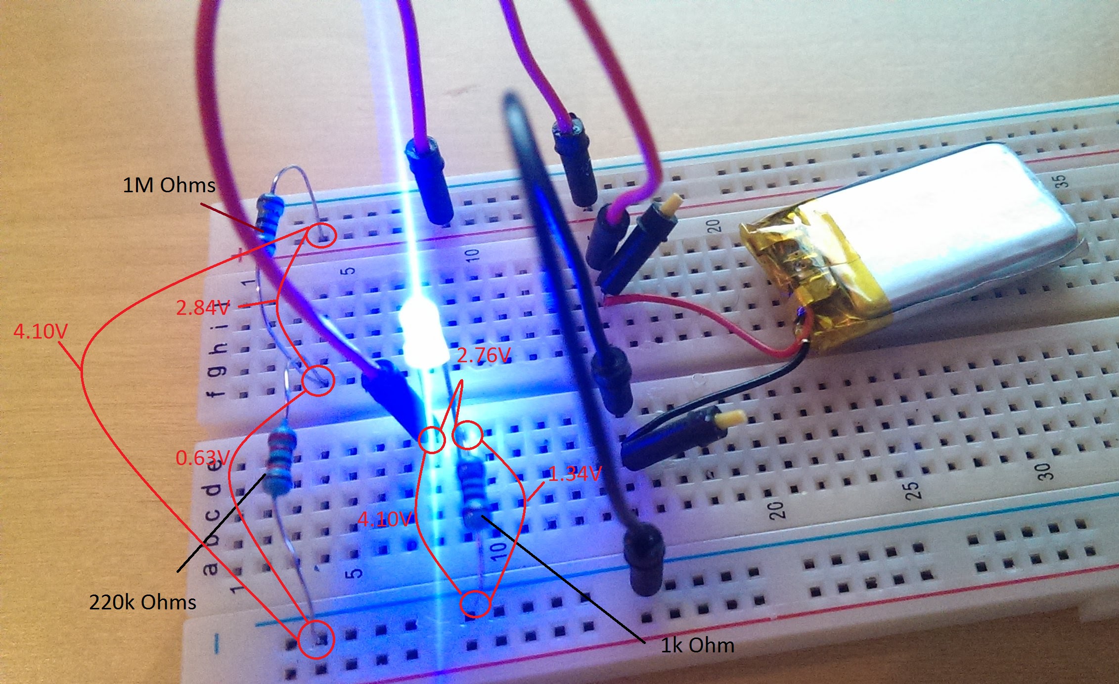
Removed all caps. Added a 1k resistor in front of the LED.
Checked resistance of wires - individually and mounted (all ~0.5 Ohm)Readings remain the same:

Where does the last "0,63V" go - and should the fact that it is the same as the current over R2 teach me something?
-
@m26872 Thank you for sticking with me.. I'm quite puzzled by this.
Removed all caps. Added a 1k resistor in front of the LED.
Checked resistance of wires - individually and mounted (all ~0.5 Ohm)Readings remain the same:

Where does the last "0,63V" go - and should the fact that it is the same as the current over R2 teach me something?
-
UPDATE:
So I decided to go ahead and connect the ProMini and nrf24l01+Now the output from the terminal fluctuated between 80% and 105% with no real pattern.
So I added a 0.22uf across R2Now the output is stable:
Battery percent: 104 %I still only measure 0.63V across R2.
I guess the remaining error could be written down to the 1.1V reference being off. I think I read somewhere that it can be 10% off! -
here is the battery related code from my battery powered temp sensor. Took a while to get the battery correct. Before this thread I had not seen any other code correcting for battery max / min voltages. I am using the 3.7V li-ion cells which actually seem to top out at 4.2V. I cap the percent at 99 for Vera.
float fmap(float x, float in_min, float in_max, float out_min, float out_max) {
  return (x - in_min) * (out_max - out_min) / (in_max - in_min) + out_min;
}

void loop()
{
  delay(dht.getMinimumSamplingPeriod());
  int sensorValue = analogRead(BATTERY_SENSE_PIN);

   // 1M, 330K divider across battery and using internal ADC ref of 1.1V
   // Sense point is bypassed with 0.1 uF cap to reduce noise at that point
   // ((1e6+330e3)/330e3)*1.1 = Vmax = 4.43 Volts
   // 4.43/1023 = Volts per bit = 0.0043336591723688
   // 4.2 = 100% 2.5 = 0%

   float batteryV  = sensorValue * 0.004333659;
   float batteryVmap = fabs(fmap(batteryV, 2.5, 4.2, 0.0, 1000.0));
   int batteryPcnt = batteryVmap / 10;
   if(batteryPcnt >= 100){
    batteryPcnt = 99;
