3 + 4 way switch with a relay
-
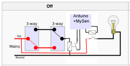
@Sefi-Ninio There is a way to solve this problem| by NOT directly connecting the original switches to the light bulb but as input on the Arduino + MySensers and control the light with an extra relais. Now the Arduino can decide to switch on of off the lamp.
And when the input is toggled e.g. when a 3-way switch is toggled the Arduino can toggle the relais as well.
I've tried to make a drawing:
-
@Sefi-Ninio There is a way to solve this problem| by NOT directly connecting the original switches to the light bulb but as input on the Arduino + MySensers and control the light with an extra relais. Now the Arduino can decide to switch on of off the lamp.
And when the input is toggled e.g. when a 3-way switch is toggled the Arduino can toggle the relais as well.
I've tried to make a drawing:
@BartE Thanks for your reply!
In your suggestion, I can see how the arduino can control the light, however I am not sure I understand how flipping a switch will turn on the light.
Do you mean that in that case, flipping a switch will cause the 2nd relay to change state, and this will allow the arduino to know that it should change the state of the 1st relay (the one that is directly connected to the lamp)? -
@BartE Thanks for your reply!
In your suggestion, I can see how the arduino can control the light, however I am not sure I understand how flipping a switch will turn on the light.
Do you mean that in that case, flipping a switch will cause the 2nd relay to change state, and this will allow the arduino to know that it should change the state of the 1st relay (the one that is directly connected to the lamp)?@Sefi-Ninio yes exactly
When the first (left) relay is toggled the Arduino sees an input change and in your Arduino sketch you can toggle the 2nd (right) relay which actually controls the lamp.
Modifying the Relay with Button example sketch should like this (where the button should be replace by the left relay:
/** * The MySensors Arduino library handles the wireless radio link and protocol * between your home built sensors/actuators and HA controller of choice. * The sensors forms a self healing radio network with optional repeaters. Each * repeater and gateway builds a routing tables in EEPROM which keeps track of the * network topology allowing messages to be routed to nodes. * * Created by Henrik Ekblad <henrik.ekblad@mysensors.org> * Copyright (C) 2013-2015 Sensnology AB * Full contributor list: https://github.com/mysensors/Arduino/graphs/contributors * * Documentation: http://www.mysensors.org * Support Forum: http://forum.mysensors.org * * This program is free software; you can redistribute it and/or * modify it under the terms of the GNU General Public License * version 2 as published by the Free Software Foundation. * ******************************* * * REVISION HISTORY * Version 1.0 - Henrik Ekblad * * DESCRIPTION * Example sketch for a "light switch" where you can control light or something * else from both HA controller and a local physical button * (connected between digital pin 3 and GND). * This node also works as a repeader for other nodes * http://www.mysensors.org/build/relay */ #include <MySensor.h> #include <SPI.h> #include <Bounce2.h> #define RELAY_PIN 3 // Arduino Digital I/O pin number for relay #define BUTTON_PIN 4 // Arduino Digital I/O pin number for button #define CHILD_ID 1 // Id of the sensor child #define RELAY_ON 1 #define RELAY_OFF 0 Bounce debouncer = Bounce(); bool state; MySensor gw; MyMessage msg(CHILD_ID,V_LIGHT); void setup() { gw.begin(incomingMessage, AUTO, true); // Send the sketch version information to the gateway and Controller gw.sendSketchInfo("Relay & Button", "1.0"); // Setup the button pinMode(BUTTON_PIN,INPUT); // Activate internal pull-up digitalWrite(BUTTON_PIN,HIGH); // After setting up the button, setup debouncer debouncer.attach(BUTTON_PIN); debouncer.interval(5); // Register all sensors to gw (they will be created as child devices) gw.present(CHILD_ID, S_LIGHT); // Make sure relays are off when starting up digitalWrite(RELAY_PIN, RELAY_OFF); // Then set relay pins in output mode pinMode(RELAY_PIN, OUTPUT); // Set relay to last known state (using eeprom storage) state = gw.loadState(CHILD_ID); digitalWrite(RELAY_PIN, state?RELAY_ON:RELAY_OFF); } /* * Example on how to asynchronously check for new messages from gw */ void loop() { gw.process(); // Get the update value if (debouncer.update()) { gw.send(msg.set(state?false:true), true); // Send new state and request ack back } } void incomingMessage(const MyMessage &message) { // We only expect one type of message from controller. But we better check anyway. if (message.isAck()) { Serial.println("This is an ack from gateway"); } if (message.type == V_LIGHT) { // Change relay state state = message.getBool(); digitalWrite(RELAY_PIN, state?RELAY_ON:RELAY_OFF); // Store state in eeprom gw.saveState(CHILD_ID, state); // Write some debug info Serial.print("Incoming change for sensor:"); Serial.print(message.sensor); Serial.print(", New status: "); Serial.println(message.getBool()); } } -
@BartE ok sounds good, thanks.
Though I'm not sure how to wire the first relay.AFAIK, switching the relay state NO/NC is controlled by the arduino Dx gpio pin, not the other way around.
So while I understand the concept, I fail to see how to wire this...
-
You need a relay that is capable of your mains voltage 230/110 V.
So you need two different types of relays:- 5 V input, 230/110V output
- 230/110V input, 5 V output
-
@Sefi-Ninio it is called a phone charger :-)
Or just this http://s.click.aliexpress.com/e/Rbq7UZRFa -
@Sefi-Ninio What about the wiring this would look like this:
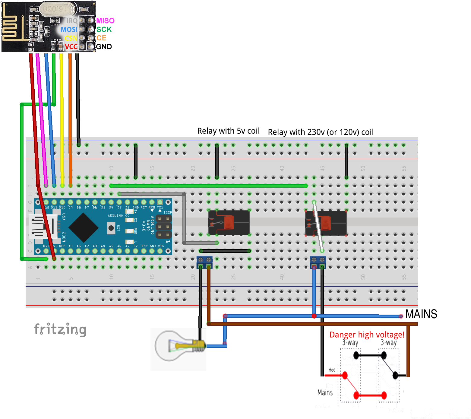
@mfalkvidd is right you can use an mobile phone charger or an USB 230v adapter plug like this
Of course a real 230v coil relay this this
-
A agree with BartE's solution, but if you want to wire everything 3-way, this is a way to do it:

Exchange any of the switches with relays.@mfalkvidd
You know?
I started thinking about instead of going with the solution @BartE suggested, I could simulate the 4way switch with 2 relay units. Then I remembered your reply and then the chip fell into place, this is just what you suggested :)Somehow, I think this solution is the best one. It it easier for me to comprehend and wire, and I think it is also more robust, as potentially, I can connect several of those along the wire if needed.
Software-wise, I think it's a simple matter of switching both relays to their NC or NO state in sync, so they both are either NO or NC, so the software is also relatively easier to implement.
I would love to hear what you guys think, though.
Thanks again for all the help, I'm learning this as I go. Software I know, but all the wirings is very new to me :)
-
I dont think the solution is what you wanted, if the arduino fails, you will not be able to turn the light on. It is good only to be able to override switches and turn lights off. I would like to come up with a full solution instead...
Hello! It looks like you're interested in this conversation, but you don't have an account yet.
Getting fed up of having to scroll through the same posts each visit? When you register for an account, you'll always come back to exactly where you were before, and choose to be notified of new replies (either via email, or push notification). You'll also be able to save bookmarks and upvote posts to show your appreciation to other community members.
With your input, this post could be even better 💗
Register Login