💬 Various bootloader files based on Optiboot 6.2
-
@Samuel235
Would you want to try a bootloader with an upload speed of 4800 ? I can make that for 8Mhz if you want (just to test)?@GertSanders, that would be fantastic if you wouldn't mind. Its for my in wall light switch custom made node that you're following. Thanks you, much appreciated.
-
@GertSanders, that would be fantastic if you wouldn't mind. Its for my in wall light switch custom made node that you're following. Thanks you, much appreciated.
here is the boot loader in 2 versions: one will flash port PB0 and the other does not.
You need to use the following fuse settings in the board file:
bootloader.low_fuses=0xE2
bootloader.high_fuses=0xDE
bootloader.extended_fuses=0x061_1458903521561_optiboot_atmega328_08M_004800_NOLED.hex
0_1458903521561_optiboot_atmega328_08M_004800_B0.hex
I saw that you use high fuse 0xDA
I'm assuming you use a boot loader larger then 512 bytes. Optiboot fits inside 512 bytes, so we need to define a space of 256 words (1 word = 2 bytes in AVR 8bit).
-
@GertSanders, that would be fantastic if you wouldn't mind. Its for my in wall light switch custom made node that you're following. Thanks you, much appreciated.
For my boot loaders based on Optiboot 6.2, I normally use high fuse set to 0xDE
Extract from my boards.txt file:
menu.mhz=CPU Speed
menu.bod=Brown Out Detection28PinBoard.name=atmega328p based - 28 pin DIL
28PinBoard.upload.tool=arduino:avrdude
28PinBoard.upload.protocol=arduino
28PinBoard.upload.maximum_size=32256
28PinBoard.upload.maximum_data_size=204828PinBoard.bootloader.tool=arduino:avrdude
28PinBoard.bootloader.unlock_bits=0x3F
28PinBoard.bootloader.lock_bits=0x0F28PinBoard.build.core=arduino:arduino
28PinBoard.build.mcu=atmega328p28PinBoard.build.board=AVR_GERTSANDERS28PinBoard
28PinBoard.build.variant=28PinBoard28PinBoard.menu.bod.4v3=4V3
28PinBoard.menu.bod.4v3.bootloader.extended_fuses=0x04
28PinBoard.menu.bod.2v7=2V7
28PinBoard.menu.bod.2v7.bootloader.extended_fuses=0x05
28PinBoard.menu.bod.1v8=1V8
28PinBoard.menu.bod.1v8.bootloader.extended_fuses=0x06
28PinBoard.menu.bod.off=Disabled
28PinBoard.menu.bod.off.bootloader.extended_fuses=0x0728PinBoard.menu.mhz.8Mi-38K4-D8= 8Mhz - internal - 38K4 - D8
28PinBoard.menu.mhz.8Mi-38K4-D8.bootloader.low_fuses=0xE2
28PinBoard.menu.mhz.8Mi-38K4-D8.bootloader.high_fuses=0xDE
28PinBoard.menu.mhz.8Mi-38K4-D8.build.f_cpu=8000000L
28PinBoard.menu.mhz.8Mi-38K4-D8.upload.speed=38400
28PinBoard.menu.mhz.8Mi-38K4-D8.bootloader.file=myoptiboot/optiboot_atmega328_08M_038400_B0.hex -
For my boot loaders based on Optiboot 6.2, I normally use high fuse set to 0xDE
Extract from my boards.txt file:
menu.mhz=CPU Speed
menu.bod=Brown Out Detection28PinBoard.name=atmega328p based - 28 pin DIL
28PinBoard.upload.tool=arduino:avrdude
28PinBoard.upload.protocol=arduino
28PinBoard.upload.maximum_size=32256
28PinBoard.upload.maximum_data_size=204828PinBoard.bootloader.tool=arduino:avrdude
28PinBoard.bootloader.unlock_bits=0x3F
28PinBoard.bootloader.lock_bits=0x0F28PinBoard.build.core=arduino:arduino
28PinBoard.build.mcu=atmega328p28PinBoard.build.board=AVR_GERTSANDERS28PinBoard
28PinBoard.build.variant=28PinBoard28PinBoard.menu.bod.4v3=4V3
28PinBoard.menu.bod.4v3.bootloader.extended_fuses=0x04
28PinBoard.menu.bod.2v7=2V7
28PinBoard.menu.bod.2v7.bootloader.extended_fuses=0x05
28PinBoard.menu.bod.1v8=1V8
28PinBoard.menu.bod.1v8.bootloader.extended_fuses=0x06
28PinBoard.menu.bod.off=Disabled
28PinBoard.menu.bod.off.bootloader.extended_fuses=0x0728PinBoard.menu.mhz.8Mi-38K4-D8= 8Mhz - internal - 38K4 - D8
28PinBoard.menu.mhz.8Mi-38K4-D8.bootloader.low_fuses=0xE2
28PinBoard.menu.mhz.8Mi-38K4-D8.bootloader.high_fuses=0xDE
28PinBoard.menu.mhz.8Mi-38K4-D8.build.f_cpu=8000000L
28PinBoard.menu.mhz.8Mi-38K4-D8.upload.speed=38400
28PinBoard.menu.mhz.8Mi-38K4-D8.bootloader.file=myoptiboot/optiboot_atmega328_08M_038400_B0.hex@GertSanders I used that DA high fuse simply to make sure the default bootloader fitted, however if its too big will it cause issues on serial ipload even if its a very small upload? Could that be the reason?
I will try your bootloader without the LED as my module doesn't contain the LED. This is very hard to read from a mobile device so i will attempt this when i get home tonight. Thank you once again for your files and time.
-
@carlierd
In sleep mode it does not matter which frequency is used. The watchdog timer runs off its own clock and that is the same for all three cases. The fact that you get around 4 uA is just because you still have a watchdogtimer running. With full deep sleep and complete shutdown of the radio we should see 1-2 uA if external pullup of more then 2MOhm is used.
The mcu frequency is important for the active time. Higher frequency means faster startup and faster completion of tasks.
8Mhz is a good compromise as the internal oscillator is less powerhungry then fullswing crystal.
And you need less parts.@GertSanders Hello. I tried the full deep sleep and it's really amazing !
I used your 8MHz with internal crystal and B0 led, BOD disabled. RFM69 for radio and just a switch via a 10MOhm resistor.
With the switch open: 280nA
With the switch close: 580nAMeasures done with a uCurrent Gold.
So I am sure now that I found the good bootloader for my application. It's simple to install and I can change easily the BOD !
Thanks ! -
@GertSanders Hello. I tried the full deep sleep and it's really amazing !
I used your 8MHz with internal crystal and B0 led, BOD disabled. RFM69 for radio and just a switch via a 10MOhm resistor.
With the switch open: 280nA
With the switch close: 580nAMeasures done with a uCurrent Gold.
So I am sure now that I found the good bootloader for my application. It's simple to install and I can change easily the BOD !
Thanks !@carlierd
Great to hear those low consumption numbers. -
@carlierd
Great to hear those low consumption numbers.@GertSanders
Yes, very impressive ! But finally not a lot of difference with the same node using interruption and sleep.
The auto-discharge of AA batteries is really important compare to node consumption.David.
-
For my boot loaders based on Optiboot 6.2, I normally use high fuse set to 0xDE
Extract from my boards.txt file:
menu.mhz=CPU Speed
menu.bod=Brown Out Detection28PinBoard.name=atmega328p based - 28 pin DIL
28PinBoard.upload.tool=arduino:avrdude
28PinBoard.upload.protocol=arduino
28PinBoard.upload.maximum_size=32256
28PinBoard.upload.maximum_data_size=204828PinBoard.bootloader.tool=arduino:avrdude
28PinBoard.bootloader.unlock_bits=0x3F
28PinBoard.bootloader.lock_bits=0x0F28PinBoard.build.core=arduino:arduino
28PinBoard.build.mcu=atmega328p28PinBoard.build.board=AVR_GERTSANDERS28PinBoard
28PinBoard.build.variant=28PinBoard28PinBoard.menu.bod.4v3=4V3
28PinBoard.menu.bod.4v3.bootloader.extended_fuses=0x04
28PinBoard.menu.bod.2v7=2V7
28PinBoard.menu.bod.2v7.bootloader.extended_fuses=0x05
28PinBoard.menu.bod.1v8=1V8
28PinBoard.menu.bod.1v8.bootloader.extended_fuses=0x06
28PinBoard.menu.bod.off=Disabled
28PinBoard.menu.bod.off.bootloader.extended_fuses=0x0728PinBoard.menu.mhz.8Mi-38K4-D8= 8Mhz - internal - 38K4 - D8
28PinBoard.menu.mhz.8Mi-38K4-D8.bootloader.low_fuses=0xE2
28PinBoard.menu.mhz.8Mi-38K4-D8.bootloader.high_fuses=0xDE
28PinBoard.menu.mhz.8Mi-38K4-D8.build.f_cpu=8000000L
28PinBoard.menu.mhz.8Mi-38K4-D8.upload.speed=38400
28PinBoard.menu.mhz.8Mi-38K4-D8.bootloader.file=myoptiboot/optiboot_atmega328_08M_038400_B0.hex@GertSanders, I have just managed to make time to remake a node and troubleshoot its upload issues with your suggested solution. So i went a head, got everything made up the minimal version, MCU, caps, and programming headers. I made sure all connections were working fine, they were. I then read the fuses, all fine and dandy. I then burnt your suggested fuses of;
bootloader.low_fuses=0xE2
bootloader.high_fuses=0xDE
bootloader.extended_fuses=0x06
Then the problem came. I lost all contact to the node, tried slowing the clock rate down on AVRDUDE to read it, nothing. I've hooked up my crystal just in case it burnt it incorrectly and thought it had an external crystal, nothing there either.
I'll be honest, i'm a little confused.
-
@GertSanders, I have just managed to make time to remake a node and troubleshoot its upload issues with your suggested solution. So i went a head, got everything made up the minimal version, MCU, caps, and programming headers. I made sure all connections were working fine, they were. I then read the fuses, all fine and dandy. I then burnt your suggested fuses of;
bootloader.low_fuses=0xE2 bootloader.high_fuses=0xDE bootloader.extended_fuses=0x06Then the problem came. I lost all contact to the node, tried slowing the clock rate down on AVRDUDE to read it, nothing. I've hooked up my crystal just in case it burnt it incorrectly and thought it had an external crystal, nothing there either.
I'll be honest, i'm a little confused.
@Samuel235
I'm out of ideas myself. I have been using several boot loader versions with the LED on different pins and different upload speeds or clockspeeds, and so far all my boot loaders work on my nodes.
Maybe you should write down step by step what you do, without assuming we know which steps you take, so we can see if the procedure is correct. Other then that it could be a board issue, but then if you already have a working board which allows uploading ??? -
Here is the process i have gone through so far:
- Soldered the MCU in place.
- Soldered the ISP and FTDI header in place.
- Soldered the Capacitors and resistor in place.
- Connected the board to PC through ISP.
- Checked for continuity through-out the board on all ISP header Pins and corresponding MCU pins.
- Check for correct voltage on all of the VCC and GND points.
- Ran a fuse check on AVRDUDE and got back all the default fuses.
- Checked that your fuses were going to be okay with my board using the fuse calculator.
- Entered your suggested fuse settings into AVRDUDE and burned.
- Went to read the fuses (like i always do after burning them to double check they have been applied). Got no answer for the device.
- Disconnected and connected the board back and read fuses over and over again with no hope with all of the speed options available within AVRDUDESS.
- Connected a 8MHz external crystal and checked for fuse readings yet again, nothing.
- Came here to see if you have any idea what has happened.
I didn't even get to the point of choosing one of your bootloaders that you gave me to try, so i'm more than sure it is either a fuse problem or a board problem (which i'm doubtful of since it was working before i burned the new fuse settings).
I haven't soldered the Radio, the radio's capacitor, battery holder, or the screw terminal block. Other than that, everything else has been assembled. The only other hardware thing that it could be, but not sure why it would work until i burnt the fuse settings, is there may be a 4.7uF as one of the capacitors where it should be a 0.1uF. I have replaced the one on the reset line so i can guarantee it is not that one. The only other caps on the board are decoupling/filtering caps.
I do already have one board with the fuses that you saw me use before (which you questioned why i used the size of the boot sector that i did) and that is working perfectly fine. But as you know that is just running a sketch that was uploaded through "Upload using programmer".
-
Here is the process i have gone through so far:
- Soldered the MCU in place.
- Soldered the ISP and FTDI header in place.
- Soldered the Capacitors and resistor in place.
- Connected the board to PC through ISP.
- Checked for continuity through-out the board on all ISP header Pins and corresponding MCU pins.
- Check for correct voltage on all of the VCC and GND points.
- Ran a fuse check on AVRDUDE and got back all the default fuses.
- Checked that your fuses were going to be okay with my board using the fuse calculator.
- Entered your suggested fuse settings into AVRDUDE and burned.
- Went to read the fuses (like i always do after burning them to double check they have been applied). Got no answer for the device.
- Disconnected and connected the board back and read fuses over and over again with no hope with all of the speed options available within AVRDUDESS.
- Connected a 8MHz external crystal and checked for fuse readings yet again, nothing.
- Came here to see if you have any idea what has happened.
I didn't even get to the point of choosing one of your bootloaders that you gave me to try, so i'm more than sure it is either a fuse problem or a board problem (which i'm doubtful of since it was working before i burned the new fuse settings).
I haven't soldered the Radio, the radio's capacitor, battery holder, or the screw terminal block. Other than that, everything else has been assembled. The only other hardware thing that it could be, but not sure why it would work until i burnt the fuse settings, is there may be a 4.7uF as one of the capacitors where it should be a 0.1uF. I have replaced the one on the reset line so i can guarantee it is not that one. The only other caps on the board are decoupling/filtering caps.
I do already have one board with the fuses that you saw me use before (which you questioned why i used the size of the boot sector that i did) and that is working perfectly fine. But as you know that is just running a sketch that was uploaded through "Upload using programmer".
@Samuel235
One possible reason: the BOD setting is now 0x06, which is the value if you use the Arduino IDE to burn the bootloader and set the fuses.
Since you use AVRDUDE ditectly, the extended fuse needs a different value (the one you get from the AVR fuse calculator at ATMEL).
I'm using my phone for this reply, so can not check the actual site right now -
@Samuel235
One possible reason: the BOD setting is now 0x06, which is the value if you use the Arduino IDE to burn the bootloader and set the fuses.
Since you use AVRDUDE ditectly, the extended fuse needs a different value (the one you get from the AVR fuse calculator at ATMEL).
I'm using my phone for this reply, so can not check the actual site right now@GertSanders, you're correct in that. I encountered this issue with my first board but the avrdude still contacted the board unlike this one. To test this out would you suggest me trying to burn the bootloader with the Arduino IDE?
I will attempt this tomorrow if so.
-
@GertSanders, you're correct in that. I encountered this issue with my first board but the avrdude still contacted the board unlike this one. To test this out would you suggest me trying to burn the bootloader with the Arduino IDE?
I will attempt this tomorrow if so.
@Samuel235
I just checked the avr calculator.
The extended fuse is FE for a BOD at 1.8V
Low E2 means internal oscillator. So that should be OK.I always use an arduino as ISP programmer when loading a bootloader onto a blank atmega328.
Tomorrow I will also test a new board with the AU variant (smd) of the mcu. Should be similar to your setup.
-
Just to keep you updated on the situation @GertSanders;
I have now double checked it hasn't burnt a external 8MHz crystal fuse setting, which it hasn't. I can't check for 16MHz setting as i do not have a 16MHz crystal or a board with one on. I will be making a new board later with a fresh MCU to see if it happens all over again. I need to stock up on 0.1uF caps to make any more boards after this one today so this is my only option for the moment.
Keep me posted on your AU style board that you're assembling today :)
EDIT/UPDATE
After remaking another board, the only thing i can think i did incorrectly was burn a high fuse of 0xEE. This would disable all SPI downloads and turn on watch dog timer. Do you think this may be whats happened here?
The new board is working perfectly fine. I've burnt the correct fuses and can read the fuses back.
I have downloaded your bootloader you included above (optiboot_atmega328_08m_004800_noled.hex). I made a new directory in 'C:\Program Files (x86)\Arduino\hardware\arduino\avr\bootloaders' called gertsoptiboot and saved the .hex file inside of there. So the overall directory of the bootloader is: 'C:\Program Files (x86)\Arduino\hardware\arduino\avr\bootloaders\gertsoptiboot\optiboot_atmega328_08m_004800_noled.hex'.
The board.txt file i have added your included text in there but i assumed that i need to change the bootloader file path and name, so my boards.txt entry for you looks like this;
##############################################################
##                        GERTSANDERS                       ##
##############################################################

menu.mhz=CPU Speed
menu.bod=Brown Out Detection

28PinBoard.name=atmega328p based - 28 pin DIL

28PinBoard.upload.tool=arduino:avrdude
28PinBoard.upload.protocol=arduino
28PinBoard.upload.maximum_size=32256
28PinBoard.upload.maximum_data_size=2048

28PinBoard.bootloader.tool=arduino:avrdude

28PinBoard.bootloader.unlock_bits=0x3F
28PinBoard.bootloader.lock_bits=0x0F

28PinBoard.build.core=arduino:arduino
28PinBoard.build.mcu=atmega328p

28PinBoard.build.board=AVR_GERTSANDERS28PinBoard
28PinBoard.build.variant=28PinBoard

28PinBoard.menu.bod.4v3=4V3
28PinBoard.menu.bod.4v3.bootloader.extended_fuses=0x04
28PinBoard.menu.bod.2v7=2V7
28PinBoard.menu.bod.2v7.bootloader.extended_fuses=0x05
28PinBoard.menu.bod.1v8=1V8
28PinBoard.menu.bod.1v8.bootloader.extended_fuses=0x06
28PinBoard.menu.bod.off=Disabled
28PinBoard.menu.bod.off.bootloader.extended_fuses=0x07

28PinBoard.menu.mhz.8Mi-38K4-D8= 8Mhz - internal - 38K4 - D8
28PinBoard.menu.mhz.8Mi-38K4-D8.bootloader.low_fuses=0xE2
28PinBoard.menu.mhz.8Mi-38K4-D8.bootloader.high_fuses=0xDE
28PinBoard.menu.mhz.8Mi-38K4-D8.build.f_cpu=8000000L
28PinBoard.menu.mhz.8Mi-38K4-D8.upload.speed=4800
28PinBoard.menu.mhz.8Mi-38K4-D8.bootloader.file=gertsoptiboot/optiboot_atmega328_08m_004800_noled.hex
I have changed the bottom two lines and will change the arduino menu name when its working. While this all like fine to me (obviously point out any errors for me here if i have done any) I'm getting a little error of "pins_arduino.h: No such file or directory". I have done a little searching around and basically i think its because i do not have a variant folder for this board/entry. I'm assuming that you have a subfolder inside of 'C:\Program Files (x86)\Arduino\hardware\arduino\avr\variants' titled something like "28PinBoard"?
To fix my issue i think i either need a copy of your variant folder OR to change the variant inside of boards.txt to that of something like 28PinBoard.build.variant=arduino:standard. Would this work considering there is nothing different on my MCU to that of a arduino board?
So here is my update: on my board I was able to upload my boot loader for 8MHz internal oscillator, with 34K8 upload speed and a led on pin D8. Here is the board running the "blink" sketch:
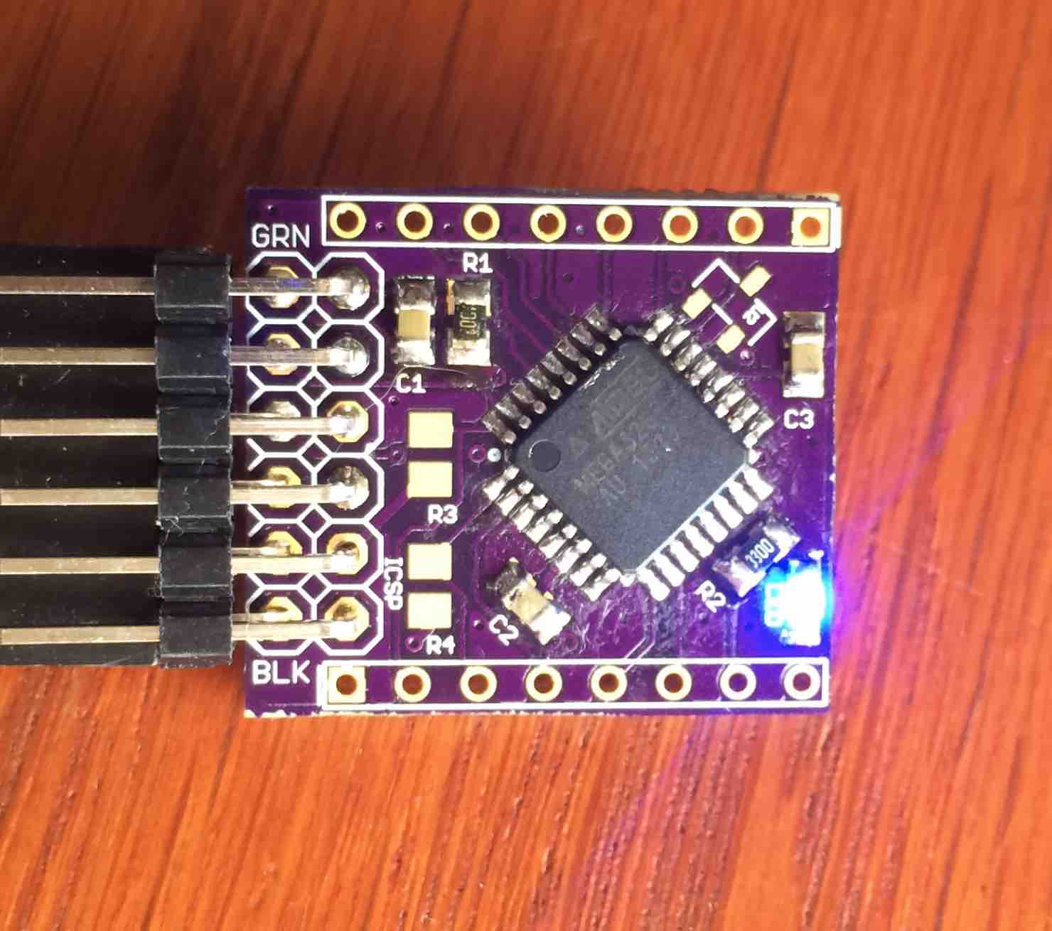
To make life easier I have zipped my complete folder, which I keep under the "hardware" folder in the sketches folder:
0_1460809951141_atmega328p.zip
I started with loading the ISP sketch on my Uno compatible board (it is set up for loading boot loaders on DIL type of atmega328):
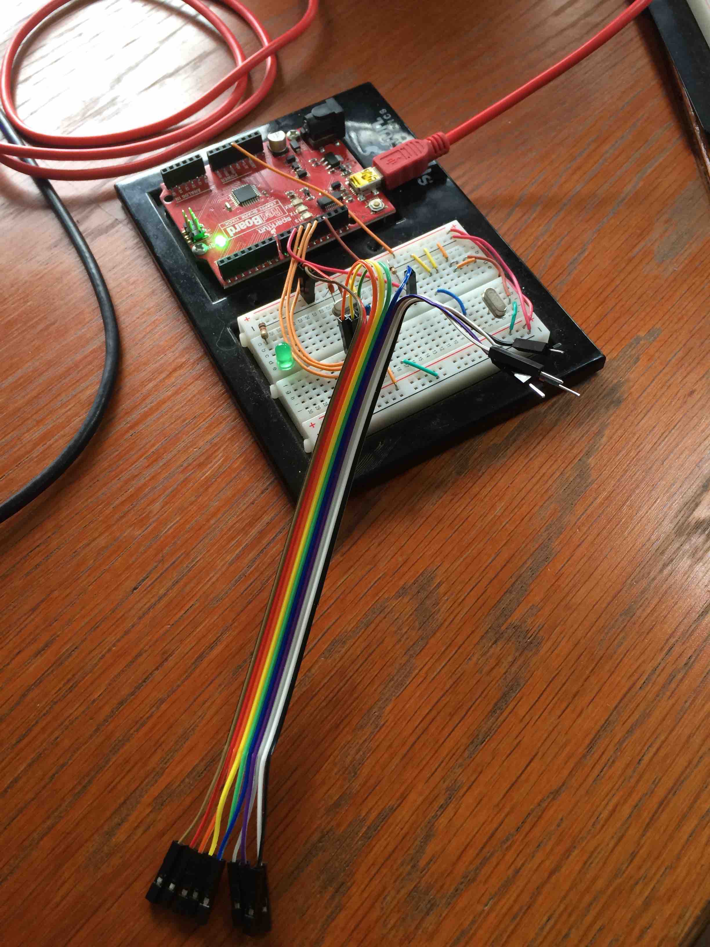
Then I choose the following settings in the Arduino IDE:
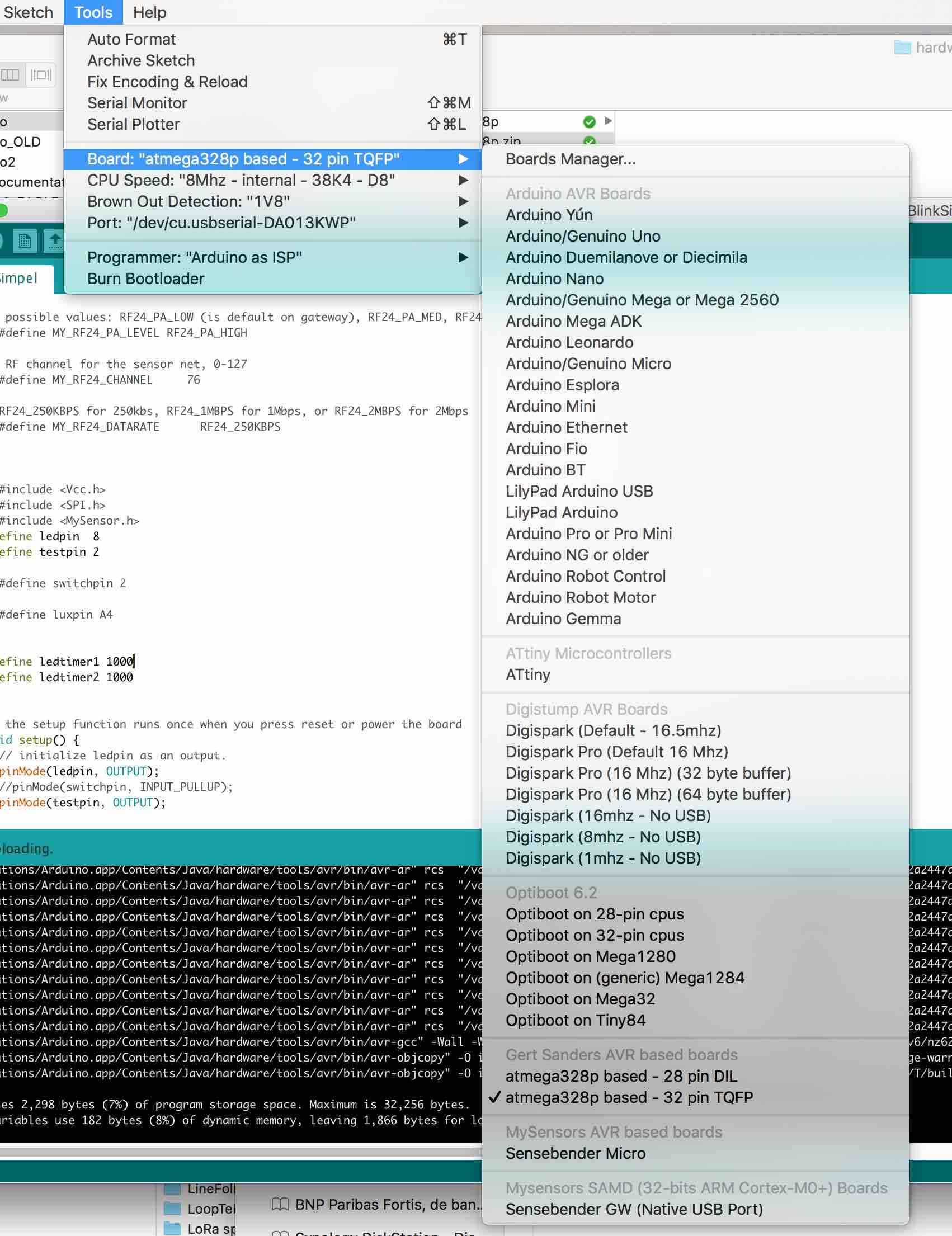
After choosing these settings I selected "Burn Bootloader", which resulted in a good loading. Since there is no sketch yet, my board cycles through a reset fase (and thus the LED blinks three times every few seconds).
After that I selected my FTDI interface and uploaded the BLINK sketch with the same settings, and bingo: blinky lights.
My next step will now be to add the radio and do a LED dimming test, to be continued ...
-
So here is my update: on my board I was able to upload my boot loader for 8MHz internal oscillator, with 34K8 upload speed and a led on pin D8. Here is the board running the "blink" sketch:
To make life easier I have zipped my complete folder, which I keep under the "hardware" folder in the sketches folder:
0_1460809951141_atmega328p.zip
I started with loading the ISP sketch on my Uno compatible board (it is set up for loading boot loaders on DIL type of atmega328):
Then I choose the following settings in the Arduino IDE:
After choosing these settings I selected "Burn Bootloader", which resulted in a good loading. Since there is no sketch yet, my board cycles through a reset fase (and thus the LED blinks three times every few seconds).
After that I selected my FTDI interface and uploaded the BLINK sketch with the same settings, and bingo: blinky lights.
My next step will now be to add the radio and do a LED dimming test, to be continued ...
@GertSanders I will test this as we speak! May I ask if there is a difference between your DIL and TQFP entries in your boards.txt?
-
@GertSanders I will test this as we speak! May I ask if there is a difference between your DIL and TQFP entries in your boards.txt?
In the boards.txt you will see additional entries for the 32 pin version. These are basically a repeat of all the inputs for the 28 pin version.
So yes, there is a difference in the boards.txt file, but the boot loaders remain the same.
-
In the boards.txt you will see additional entries for the 32 pin version. These are basically a repeat of all the inputs for the 28 pin version.
So yes, there is a difference in the boards.txt file, but the boot loaders remain the same.
@GertSanders I'm sorry, I didn't look inside of the folder your provided before i asked that question.
-
Last update on this topic to save bogging it down now, just to assist anyone else looking to use your bootloaders. I have managed to upload sketches to my MCU. I'm running the 'optiboot_atmega328_08m_004800_noled.hex' bootloader with the following boards.txt entry:
##############################################################
##                        GERTSANDERS                       ##
##############################################################

menu.mhz=CPU Speed
menu.bod=Brown Out Detection

28PinBoard.name=atmega328p based - 28 pin DIL

28PinBoard.upload.tool=arduino:avrdude
28PinBoard.upload.protocol=arduino
28PinBoard.upload.maximum_size=32256
28PinBoard.upload.maximum_data_size=2048

28PinBoard.bootloader.tool=arduino:avrdude

28PinBoard.bootloader.unlock_bits=0x3F
28PinBoard.bootloader.lock_bits=0x0F

28PinBoard.build.core=arduino:arduino
28PinBoard.build.mcu=atmega328p

28PinBoard.build.board=AVR_GERTSANDERS28PinBoard
28PinBoard.build.variant=28PinBoard

28PinBoard.menu.bod.4v3=4V3
28PinBoard.menu.bod.4v3.bootloader.extended_fuses=0x04
28PinBoard.menu.bod.2v7=2V7
28PinBoard.menu.bod.2v7.bootloader.extended_fuses=0x05
28PinBoard.menu.bod.1v8=1V8
28PinBoard.menu.bod.1v8.bootloader.extended_fuses=0x06
28PinBoard.menu.bod.off=Disabled
28PinBoard.menu.bod.off.bootloader.extended_fuses=0x07

28PinBoard.menu.mhz.8Mi-38K4-D8= 8Mhz - internal - 4K8 - D8
28PinBoard.menu.mhz.8Mi-38K4-D8.bootloader.low_fuses=0xE2
28PinBoard.menu.mhz.8Mi-38K4-D8.bootloader.high_fuses=0xDE
28PinBoard.menu.mhz.8Mi-38K4-D8.build.f_cpu=8000000L
28PinBoard.menu.mhz.8Mi-38K4-D8.upload.speed=4800
28PinBoard.menu.mhz.8Mi-38K4-D8.bootloader.file=gertsoptiboot/optiboot_atmega328_08m_004800_noled.hex
I'de like to thank you for the time and effort you have put in to assist me on this problem. I will be making entries for the rest of your bootloaders that you have also kindly given to us. I'll be changing this to a faster upload speed bootloader variant to allow for quicker uploads, maybe the 'optiboot_atmega328_08M_038400_NOLED.hex'. Would you advise me to use this bootloader with the correct boards.txt entry for it, would it be okay to have on my switch node permanently or is there something in there that wouldn't make it appropriate?
After seeing the extent that you have gone to with your customization with the bootloaders, it has inspired me to get into bootloaders myself. All in due time.
Thank you once again :)
-
I have upgraded my Arduino to 1.6.8, running Ubuntu 14.04LTS and downloaded the GertSander great optiboot :-)
I use Arduino Pro mini clones from ebay. I have removed power LED and LDO, since those shall be powered from 2pcs AAA . I can read "80e" on the crystal - I assume this is 8MHz
But I get weird troubles, I can flash bootloader via TinyUSB and upload sketch via FTDI, but not the lower frequencies like 1MHz or 4MHz, my working sketch upload is with 8 MHz (I have not tried with a higer freq). I can upload both using internal and external crystal settings. I use BOD=1.8V
I have been suspecting my USB cable to MiniUSB to FTDI, but it's working when I use the 8MHz frequencey and 38K4baud rate
any good ideas?
Hello! It looks like you're interested in this conversation, but you don't have an account yet.
Getting fed up of having to scroll through the same posts each visit? When you register for an account, you'll always come back to exactly where you were before, and choose to be notified of new replies (either via email, or push notification). You'll also be able to save bookmarks and upvote posts to show your appreciation to other community members.
With your input, this post could be even better 💗
Register Login