Skip to content
  • MySensors
  • OpenHardware.io
  • Categories
  • Recent
  • Tags
  • Popular
Skins
  • Light
  • Brite
  • Cerulean
  • Cosmo
  • Flatly
  • Journal
  • Litera
  • Lumen
  • Lux
  • Materia
  • Minty
  • Morph
  • Pulse
  • Sandstone
  • Simplex
  • Sketchy
  • Spacelab
  • United
  • Yeti
  • Zephyr
  • Dark
  • Cyborg
  • Darkly
  • Quartz
  • Slate
  • Solar
  • Superhero
  • Vapor

  • Default (No Skin)
  • No Skin
Collapse
Brand Logo
  1. Home
  2. Hardware
  3. Sensebender/Dualoptiboot OTA HowTo in Mysensors

Sensebender/Dualoptiboot OTA HowTo in Mysensors

Scheduled Pinned Locked Moved Hardware
25 Posts 10 Posters 12.9k Views 18 Watching
  • Oldest to Newest
  • Newest to Oldest
  • Most Votes
Reply
  • Reply as topic
Log in to reply
This topic has been deleted. Only users with topic management privileges can see it.
  • scalzS Offline
    scalzS Offline
    scalz
    Hardware Contributor
    wrote on last edited by
    #7

    @emc2
    thx.
    you can use example sketch from spiflash lib ;)

    1 Reply Last reply
    0
    • E Offline
      E Offline
      emc2
      Hardware Contributor
      wrote on last edited by
      #8

      This one? https://github.com/mysensors/Arduino/blob/development/libraries/SPIFlash/examples/SPIFlash_ReadWrite/SPIFlash_ReadWrite.ino

      Great I will give it a try tonight!

      By the way, is it me or in the current dev branch lost https://github.com/mysensors/Arduino/tree/fb1c542862221f0678485a553b46120bf09c6a91/libraries/MySensors/examples/Sha204Personalizer at some point?

      1 Reply Last reply
      0
      • E Offline
        E Offline
        emc2
        Hardware Contributor
        wrote on last edited by
        #9
        Start...Init FAIL!
        

        Well I guess something is wrong

        1 Reply Last reply
        0
        • scalzS Offline
          scalzS Offline
          scalz
          Hardware Contributor
          wrote on last edited by
          #10

          @emc2
          depending on the eeprom you're using, you may need to change the corresponding jedec code in the sketch (I don't remember well). you can find the eeprom jedec code in datasheet if not the same. but in mysensors it should work. or you have a bad wiring perhaps..

          1 Reply Last reply
          1
          • E Offline
            E Offline
            emc2
            Hardware Contributor
            wrote on last edited by
            #11

            Got it, thanks @scalz !

            I had indeed to remove the ID from

            SPIFlash flash(FLASH_SS, 0xEF30);
            

            and leave it blank (or use 0x1F65 for the AT25DF512C):

            SPIFlash flash(FLASH_SS);
            

            Next step OTA flashing... but tomorrow.

            1 Reply Last reply
            0
            • scalzS Offline
              scalzS Offline
              scalz
              Hardware Contributor
              wrote on last edited by
              #12

              :thumbsup:

              1 Reply Last reply
              0
              • alexsh1A Offline
                alexsh1A Offline
                alexsh1
                wrote on last edited by
                #13

                I have AT25512N-SH-T SOIC-8 -> http://www.mouser.com/ds/2/36/Atmel-5165-SEEPROM-AT25512-Datasheet-476711.pdf
                I so have a different bootloader - http://www.boardstuff.co.uk. I think I can use it with the flash as it does have 8 pins socket.

                However, I am a complete noob when it comes to the OTA. Is this the way to do it:

                1. Burn Optiboot onto the Sensebender
                2. Why do you have external eeprom board? I think the Sensebender has 64kb SPI flash / e2prom onboard.

                Thanks for an excellent tutorial.

                1 Reply Last reply
                0
                • scalzS Offline
                  scalzS Offline
                  scalz
                  Hardware Contributor
                  wrote on last edited by
                  #14

                  @alexsh1
                  i don't know for your eeprom, i don't have time right now, but that need to check datasheet, same pin footprint is not enough.

                  1. you need to burn DualOptiboot, it's not optiboot. Optiboot does not handle ota.
                  2. The board is an eval board for ota/auth. that's all. it could be used in some diy projects but i integrate the eeprom on my pcbs of course.
                  1 Reply Last reply
                  0
                  • alexsh1A Offline
                    alexsh1A Offline
                    alexsh1
                    wrote on last edited by
                    #15

                    @scalz Thanks! The sensebender had already the eeprom IC right? So no need to do anything external

                    1 Reply Last reply
                    0
                    • scalzS Offline
                      scalzS Offline
                      scalz
                      Hardware Contributor
                      wrote on last edited by scalz
                      #16

                      @alexsh1 yes, no need. thx for feedback. I will modify my howto and add a link to the post relating eeprom compatibility too.

                      alexsh1A 1 Reply Last reply
                      0
                      • scalzS scalz

                        @alexsh1 yes, no need. thx for feedback. I will modify my howto and add a link to the post relating eeprom compatibility too.

                        alexsh1A Offline
                        alexsh1A Offline
                        alexsh1
                        wrote on last edited by
                        #17

                        @scalz only the bootloader change to Dualoptiboot on a node is required with some change of code, right? Does eeprom IC have to be programed as well or it is fully changed by Dualoptiboot + sketch?

                        1 Reply Last reply
                        0
                        • KoreshK Offline
                          KoreshK Offline
                          Koresh
                          Contest Winner
                          wrote on last edited by Koresh
                          #18

                          Thanks for this incredible tutorial. :thumbsup:
                          I've found almost all answers here and now I want only confirmation of my thoughts :)
                          I am prepearing my Wall Socket insertable node for production so I am making latest changes on the board. I decided to add SPI flash to implement OTA ability (see picture - U5). I plan to use dualboot.
                          alt text
                          As I understand the sketch works during loading firmware over the air, so it doesn't matter how much time it takes because my sketch can send heartbeat impulses to external watchdog during updating. Is it correct?
                          Second, I didn't want to add spi flash to Wall switch insertable node, but now I am having doubts. If I understand correctly there is no problem to update sleeping node because it will get update messages when it wakes up. Is it true? :)
                          Thanks!

                          martinhjelmareM 1 Reply Last reply
                          0
                          • scalzS Offline
                            scalzS Offline
                            scalz
                            Hardware Contributor
                            wrote on last edited by
                            #19

                            @koresh thx i'm glad if it helped you.

                            1. not sure what you mean with "how much time... because external wdt". I was referring about the time it could take for battery powered device. because some sensors lib can have delays for instance, and keeping the readings process during ota could slow ota reception. but I have not checked the behaviour in the new lib yet.
                            2. I think so, depending of the controller used.
                            1 Reply Last reply
                            0
                            • KoreshK Koresh

                              Thanks for this incredible tutorial. :thumbsup:
                              I've found almost all answers here and now I want only confirmation of my thoughts :)
                              I am prepearing my Wall Socket insertable node for production so I am making latest changes on the board. I decided to add SPI flash to implement OTA ability (see picture - U5). I plan to use dualboot.
                              alt text
                              As I understand the sketch works during loading firmware over the air, so it doesn't matter how much time it takes because my sketch can send heartbeat impulses to external watchdog during updating. Is it correct?
                              Second, I didn't want to add spi flash to Wall switch insertable node, but now I am having doubts. If I understand correctly there is no problem to update sleeping node because it will get update messages when it wakes up. Is it true? :)
                              Thanks!

                              martinhjelmareM Offline
                              martinhjelmareM Offline
                              martinhjelmare
                              Plugin Developer
                              wrote on last edited by
                              #20

                              @Koresh

                              Make sure you wait for a little bit (~300 ms) before going back to sleep in the sketch, to give the controller time to send the reboot command to the node. The firmware config request is sent from the node in the begin method.

                              When I implemented firmware updates in the pymysensors library I made sure to only send the reboot command after receiving a set command from a node. That way the node should be awake to receive the reboot command if it waits a bit before going back to sleep. I'm not sure how the other controllers that support ota firmware updates have solved this.

                              1 Reply Last reply
                              0
                              • V Offline
                                V Offline
                                vikasjee
                                wrote on last edited by vikasjee
                                #21

                                Any sample optimised sketch for the OTA enabled sketch?

                                1 Reply Last reply
                                0
                                • M Offline
                                  M Offline
                                  manutremo
                                  wrote on last edited by
                                  #22

                                  I was looking for the same and found this:

                                  https://forum.mysensors.org/topic/4923/ota-firmware-updating-is-too-slow/13

                                  1 Reply Last reply
                                  0
                                  • scalzS scalz

                                    Hi.

                                    Here is an howto about OTA in Mysensors I made for jeedom french users when Mysensors 1.5 was released. So I translated it if it can be useful to you. Things should not have changed a lot I think. I have no time for the moment to check everything. So if you note differences, tell me here and I will update. I will update pics with latest revision of the software.

                                    OTA, or Over The Air, lets you upload your sketch without ftdi, it's done wirelessly. Can be useful if your nodes are not accessible or you need to make signing changes for instance. To get this nice feature, you need to burn a dedicated bootloader.

                                    In Mysensors, we can use two kind of OTA:

                                    • 1st option : MYSBootloader, created by Tekka from Mysensors Team.
                                    • 2nd option : Dualoptiboot or if you prefer Sensebender Bootloader (in Mysensors boards). But in this tutorial I will name it "Dualoptiboot". It comes from Lowpowerlab.

                                    Difference between these two methods (updated from Tekka post http://forum.mysensors.org/topic/3453/mysbootloader-1-3-pre-release-myscontroller-1-0-0beta/9)

                                    • MYSBootloader does not require external flash: OTA FW updates are transmitted offline, i.e. MYSBootloader communicates with the controller and receives new FW which is directly written to MCU, once FW is transmitted and CRC verified, MYSBootloader hands over to the new sketch/FW.
                                      Pro: recovery OTA possible, also with a faulty/buggy sketch (if sketch freezes, watchdog resets and MYSBootloader takes over), no external flash required
                                      Cons: Radio specific, i.e. different bootloader for RF24 and RFM69 radio (rfm69 work in progess) necessary, offline (no sensor data processing possible during ota).
                                    • Dualoptiboot requires external flash: OTA FW updates are transmitted online, i.e. while the node is active. Once all FW packets are transmitted and CRC verified, the node reboots, dualoptiboot copies FW from external flash to MCU and hands over to the new sketch/FW.
                                      That means too that you need to ftdi upload your node sketch the first time or ota won't work yet as it is handled in the sketch.
                                      Pro: Radio agnostic (no radio specific code in bootloader so can be used in different scheme/protocols..), online (while node processes sensor data)
                                      Cons: Faulty FW (e.g. freezing sketch due to bad coding) cannot be recovered OTA => recovery via serial port necessary, external flash required

                                    This tutorial is only for Dualoptiboot Bootloader, because I have not seen an howto for this option here yet. But some parts/pictures of this howto can be used for MYSBootloader upload.
                                    If you want to use MYSBootloader, howto is here: http://forum.mysensors.org/topic/3453/mysbootloader-1-3-pre-release-myscontroller-1-0-0beta/9

                                    By default, Dualoptiboot bootloader is 8Mhz Internal + 1.8V BOD.

                                    What do you need:

                                    • SPI eeprom, jedec compliant, like AT25DF512C-SSHN-B. For other eeprom and compatibility, you can check this post https://forum.mysensors.org/topic/3160/ota-flash-types-for-mysensors
                                    • for evaluation or some diy projects, I did this evalboard https://oshpark.com/shared_projects/m5Uugjx5 or you can find it on opensourcehardware. No need of course if you have a sensebender, moteino etc as eeprom is already there.
                                    • I use an USBASP to burn the bootloader
                                    • I use AVRDUDESS : http://blog.zakkemble.co.uk/avrdudess-a-gui-for-avrdude/ for fuse
                                    • arduino 1.6.x
                                    • Mysensors 1.5.x : http://www.mysensors.org/download/
                                    • MYSController : http://www.mysensors.org/controller/myscontroller
                                    • So in Arduino Ide, now you shoud see Sensebender Micro board in Boards\tools

                                    Burn Dualoptiboot in your node

                                    To keep things simple, or maybe not for others..imho it's so easy with a cheap usbasp (just few wire) than arduino as isp.

                                    What looks my usbasp (clone, USBASP 2.0 LC Technology) and connections to your arduino or node.
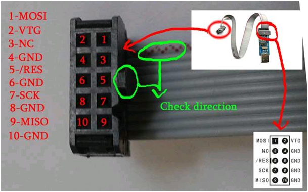
                                    0_1458993268264_737420usbasp.png
                                    Wiring on nano/micro/328p:

                                    MOSI : D11
                                    VTG : VCC 3.3V
                                    GND : GND
                                    RES : RESET
                                    SCK : D13
                                    MISO : D12
                                    

                                    Once it's wired, burn fuses with avrdudess. Here the conf:

                                    0_1458993338862_281987avrdudess.png

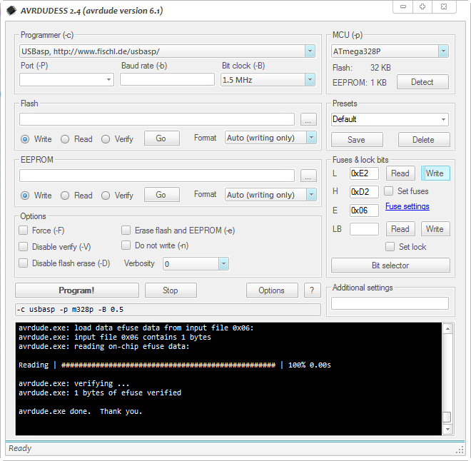
                                    Note : even if my usbasp is a clone, I choose genuine usbasp in the listbox.

                                    Just click on Write in "Fuses&Lock bits" section. Then read it to check fuses are well burned.

                                    Now don't disconnect your usbasp.

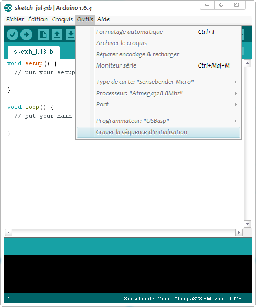
                                    • Go to arduino ide, choose SensebenderMicro, Processeur Atmel328 8Mhz, serial COM port, and USBASP programmer.
                                    • Click Tools\Burn bootloader. You will get few SCK warning but that's not a problem, it's because I have an usbasp clone.
                                      Note: you could use avrdudess to burn the bootloader too.

                                    0_1458993400230_236880arduino1.png

                                    0_1458993479899_889671arduino2.png

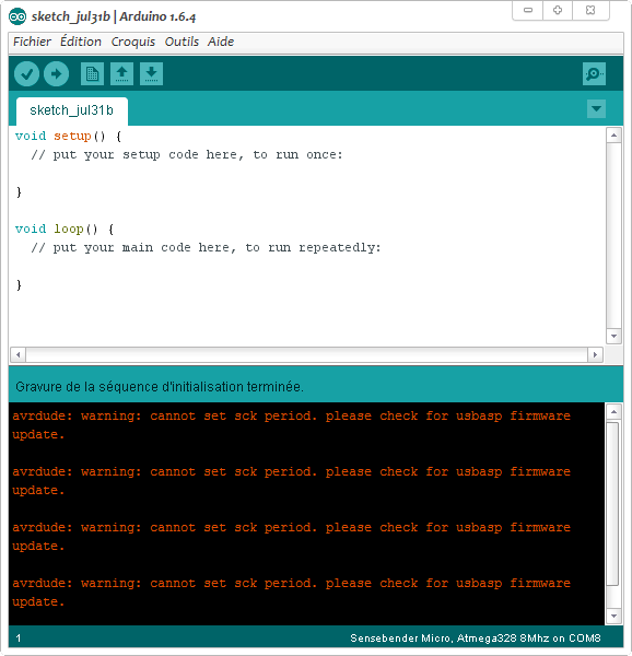
                                    Yeah, our OTA bootloader is burnt :)

                                    In sketch

                                    To enable OTA in your sketch, you need to add

                                    #define MY_OTA_FIRMWARE_FEATURE 
                                    

                                    or uncomment it in Myconfig.h

                                    OTA management is completely transparent. Everything is well handled in process() and wait() methods (when you do a gw.wait or mynode.wait for instance...)

                                    Important note :

                                    • Don't forget a sleeping node can't receive an OTA. You can wait after wakeup for instance to see if you have somethings coming or I have not tried it yet but it seems now in mysensors libs there is smartsleep() wich manage the wait() after wake up.
                                    • when you upload the new sketch, it is done during runtime, so you have to handle/optimize this in sketch. The best is if you detect an OTA msg, to pause process or sensors readings during the process or it will affect the speed of the OTA. I mean for instance if you read sensors, sometimes there are some delays in libs, all these things will delay ota or timeout it during main loop. Plus, if these optimization are not done and you run on battery, the longer time in TX/RX radio for the update, the more battery energy wasted. OTA can be fast 15-30sec if nothing slow it, or x minutes if not optimized :open_mouth:
                                      So it's up to you to manage this, use non blocking/asynchronous code. The rest of the process is again completely transparent. Great!

                                    How to upload a new sketch just with OTA

                                    For this I use MYSController. It's not an .ino file that you will upload but the .hex one. So to easily get this file:

                                    • In Arduino ide, go to File\Preferences, on bottom click on preferences.txt. It opens preferences.txt.

                                    0_1458993573312_121153arduino3.png

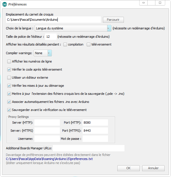
                                    • Keep this file opened and close arduino ide (otherwise your changes will be erased).
                                    • In preferences.txt, at the end, add this
                                    build.path=C:\Arduino-Output\
                                    

                                    or another preferred path. It will be there you will find your .hex compiled sketch files.

                                    • Open arduino ide and compile/check your node project. You should now see your compiled files in the path you have set.
                                    • Copy the .hex to Firmware path of MYSController

                                    Launch your OTA update

                                    • Launch MYSController and in Config/Serial, check the right serial com port.
                                    • Click on "Refresh FW repo" so you can use your new .hex file.
                                      Note : When I tested this it didn't work for me so I needed to do this
                                      In Firmware folder, edit firmware_config.csv and manually add your .hex. Here an example where I added a Humidity .hex file for tests.
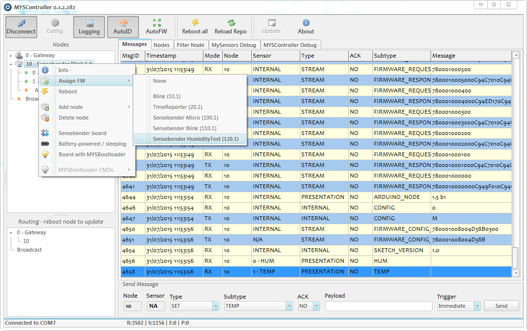
                                    Type,Name,Version,File,Comments
                                    10,Blink,1,Blink.hex,blinking example
                                    20,TimeReporter,1,TimeReporter.hex,TimeReporter
                                    100,Sensebender Micro,1,SensebenderMicro.cpp.hex,Sensebender Micro
                                    110,Sensebender Blink,1,SensebenderBlink.cpp.hex,Sensebender Blink
                                    120,Sensebender HumidityTest,1,HumiditySensor.cpp.hex,HumidityTest
                                    
                                    • Now to wirelessly send your new sketch to your node, simply right click on the node you want to update. For sleeping battery node, choose "Battery powered Sleeping". So when your node will wake up, MYSController will resend the update. Awesome!
                                    • click on Assign FW,
                                    • choose the sketch

                                    and voilà! OTA should start, and then your node will reboot.

                                    0_1458993734904_399014arduino4.png

                                    I hope to have not missed something important. Please tell me, and I will add in this post.
                                    This howto was made some months ago, so I'm note sure if it's exactly still the same, but that should be almost ok. Try and test ;) and tell me. I hope it will help at least, as it is something often asked..If all is ok, don't hesitate to put it on a better place (I'm not sure if it's the best place here)

                                    Enjoy!

                                    C Offline
                                    C Offline
                                    cvdenzen
                                    wrote on last edited by
                                    #23

                                    @scalz A useful addition could be that the controller only runs on Windows. I bumped into this limitation after quite a few succesful steps. Is there a Linux or Java alternative?

                                    scalzS 1 Reply Last reply
                                    0
                                    • C cvdenzen

                                      @scalz A useful addition could be that the controller only runs on Windows. I bumped into this limitation after quite a few succesful steps. Is there a Linux or Java alternative?

                                      scalzS Offline
                                      scalzS Offline
                                      scalz
                                      Hardware Contributor
                                      wrote on last edited by scalz
                                      #24

                                      @cvdenzen
                                      will think about it :) afaik there isn't any simpler linux or java alternative yet. I'm windows user and MYSController is very handy.
                                      that said you can take a look here for controllers supporting FOTA https://www.mysensors.org/controller , maybe MyController.org ..

                                      M 1 Reply Last reply
                                      1
                                      • scalzS scalz

                                        @cvdenzen
                                        will think about it :) afaik there isn't any simpler linux or java alternative yet. I'm windows user and MYSController is very handy.
                                        that said you can take a look here for controllers supporting FOTA https://www.mysensors.org/controller , maybe MyController.org ..

                                        M Offline
                                        M Offline
                                        manutremo
                                        wrote on last edited by
                                        #25

                                        @scalz Mycontroller works fine, I just tested it with Dualoptiboot and last package version (ask in the forum).

                                        1 Reply Last reply
                                        1
                                        Reply
                                        • Reply as topic
                                        Log in to reply
                                        • Oldest to Newest
                                        • Newest to Oldest
                                        • Most Votes


                                        19

                                        Online

                                        11.7k

                                        Users

                                        11.2k

                                        Topics

                                        113.1k

                                        Posts


                                        Copyright 2025 TBD   |   Forum Guidelines   |   Privacy Policy   |   Terms of Service
                                        • Login

                                        • Don't have an account? Register

                                        • Login or register to search.
                                        • First post
                                          Last post
                                        0
                                        • MySensors
                                        • OpenHardware.io
                                        • Categories
                                        • Recent
                                        • Tags
                                        • Popular