Glass Break Sensor as Switch
-
I have found some nice glass break sensors that don't require power. I looked up the data sheet (http://static.interlogix.com/library/75803_shock_sensor_ds.pdf) and it has a certain resistance when idle 14-24Ω. And when the sensor is tripped it has a resistance > 1MΩ. My question is this: will the arduino register 1 MΩ as open? I have the switch sketch working for door sensors and was really hoping to expand to glass break. Any help is appreciated.
@mh_alex it depends on the value of the pullup resistor. A low signal is <0.3Vcc and a high signal is >0.6Vcc (see Electrical Characteristics in the atmega328 datasheet).
The easiest way to use the sensor is to create a voltage divider by adding a pullup or pulldown resistor.
A 390kohm resistor is the largest you can use to reliably detect a shift from a few ohms to 1mohm with a simple voltage divider.
-
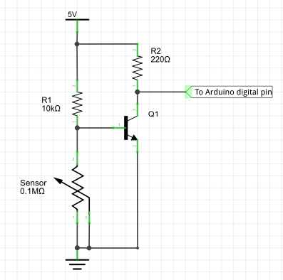
Another way to use the sensor value is a voltage divider that commands a transistor used as switch, see the schema below:
until the sensor's value is low, the voltage value applied to the transistor's base is low so it'll be OFF and at the collector we'll have Vdd, if connected to an arduino digital pin it is an HIGH digital value. When the sensor has an high value the voltage applied to the transistor's base will switch it on and since the transistor's emitter is connected to the ground the value seen at the collector is almost 0V, so LOW value at the arduino digital pin.
-
@mh_alex it depends on the value of the pullup resistor. A low signal is <0.3Vcc and a high signal is >0.6Vcc (see Electrical Characteristics in the atmega328 datasheet).
The easiest way to use the sensor is to create a voltage divider by adding a pullup or pulldown resistor.
A 390kohm resistor is the largest you can use to reliably detect a shift from a few ohms to 1mohm with a simple voltage divider.
@mfalkvidd Thank you for the quick and informative response. I'm new to Arduino and didn't know how to look for this type of information. I think i will try activating the internal pullup resistor as I have already done for my door switches. If this does not work then I will attempt to build my own voltage divider circuit. I will post my findings in the coming week.
-
Another way to use the sensor value is a voltage divider that commands a transistor used as switch, see the schema below:
until the sensor's value is low, the voltage value applied to the transistor's base is low so it'll be OFF and at the collector we'll have Vdd, if connected to an arduino digital pin it is an HIGH digital value. When the sensor has an high value the voltage applied to the transistor's base will switch it on and since the transistor's emitter is connected to the ground the value seen at the collector is almost 0V, so LOW value at the arduino digital pin.
-
@mfalkvidd Thank you for the quick and informative response. I'm new to Arduino and didn't know how to look for this type of information. I think i will try activating the internal pullup resistor as I have already done for my door switches. If this does not work then I will attempt to build my own voltage divider circuit. I will post my findings in the coming week.
-
-
It worked perfectly. I found a sketch in the forums for two switches with interrupts and wired up two glass break sensors. The sensors can be found on amazon for 12 bucks "Interlogix Glassbreak Shock Detector, White (5150W)". Thanks for the help!
Hello! It looks like you're interested in this conversation, but you don't have an account yet.
Getting fed up of having to scroll through the same posts each visit? When you register for an account, you'll always come back to exactly where you were before, and choose to be notified of new replies (either via email, or push notification). You'll also be able to save bookmarks and upvote posts to show your appreciation to other community members.
With your input, this post could be even better 💗
Register Login