Battery powered smoke sensor
-
Hi, I did not find anything about a battery powered smoke sensor.
Is that buildable, withthout changing battery every month ?
Thanks for advices :-) -
@Samuel235 is working on something like that!
-
My smoke alarm/sensor is working from AC-DC power. However, i'v created my smoke sensor through means of an optical sensor and therefor it shouldn't drain too much battery power, however it will still be a fair amount to be honest with you. It has to power an LED and then wait for a reading from a phototransistor. So, i do think it wouldn't be the best method for battery power, however it would be much much better than any ionization method out there.
I have done a bit of research to find a electrochemical sensor, but failed. If there is such a device then this would be the got to for battery powered modules as they do not require any power to sense the smoke, it works on radiation creating a current which is then converted to a voltage for the analog pin to read and detect high or low signals.
By all means take a look at my latest developing module though if you're interested: https://forum.mysensors.org/topic/3449/homini-complete-room-sensor-module
-
Thanks for that complete answer. On my side I tried to mySensorize an existing 5$ smoke sensor, without success. I found the processor pin that goes High when smoke is detected, and wanted to power an arduino with it, but the output is not enough to bring the arduino to live. It would have be a nice solution, and simple too.
I go on reading your usefull links. Thanks again. -
@Poupoune1974 - Not much fun in it - but i bought 433mhz smoke alarms and connected it to my system. Works great and I can even switch the smoke alarm on from my system - as a burgular alarm.
-
@sundberg84 Even without fun, it would do the trick :-). Would you have a link for your item ? Did you couple it with a mySensor Node, or directly in your system (I'm running Jeedom)
-
Im using RFLink connected to Domoticz. It was cheap and works great. You can also use RTXCom or Telldus i think. Im using firealarms from NEXA. I have seen those with other names on other countries. Here is some more: https://forum.mysensors.org/topic/2075/using-mysensors-for-alarm-build/13
-
I planned to build one since a while. So now I know what to do. Besides, Jeedom can integrate it.
Thanks a lot. -
You can get some inspiration from here:
http://harizanov.com/2014/07/diy-internet-of-things-fire-alarm/Quote from the above link: "The piezo siren is activated with a 200ms series of 6.5Khz 50% PWM at 9V so I had to create a small voltage divider + a capacitor to smoothen the signal out and bring it to 3V so the Funky v1 can handle it. A 4.7K:10K + 1 uF ceramic capacitor works well"
-
The link provided above looks like something that could be very high potential for the mysensors community. If my module fails and falls short of what i intend it to do, this is option i would go down. However, i wanted it to contain light sensors, temp, humidity etc etc. If i didn't need/want those sensors I would have made this solution work for myself. It looks a very nice setup.
-
I was considering how the combined smoke-detector/burglar siren device shall work:
1)
First as alarm in case of fire, send signal to home automation (Arduino can be powerdown until interrupt, low power consumption).
2)
Secondly in case of a burglar, I would like to start the piezo noise in smoke alarms - but this requires Arduino to run idle and eat up battery.
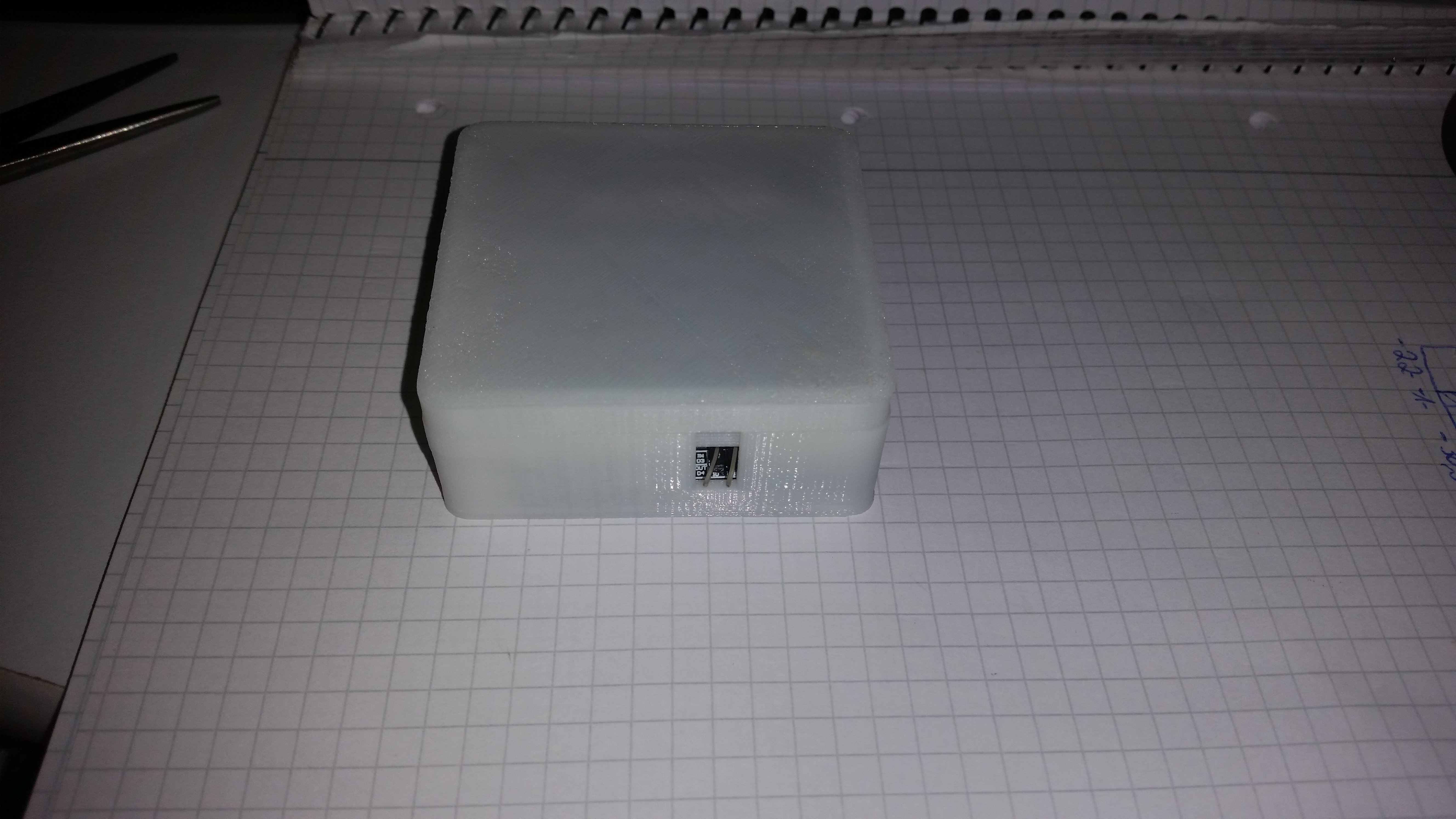
Hmm thinking about maybe it could wake-up once a minute to check status and then sleep? any other good ideas?Is it worth to spend extra money on low power Arduino Pro mini that have a better voltage LDO (MCP 1703), I saw some at 12 US$ at rocketscream - or just accept batteries are cheap to replace a bit more often?
From this link:
http://www.home-automation-community.com/arduino-low-power-how-to-run-atmega328p-for-a-year-on-coin-cell-battery/And then we wonder why most piezo devices have 3 wires, read here:
http://electronics.stackexchange.com/questions/18212/whats-the-third-wire-on-a-piezo-buzzerSo my idea for now is to use the resister 4k7 + 10k and a 1 uF ceramic capacitor. Then I could use a mosfet to activate piezo with short-circuiting the "test" switch
-
Thanks for that complete answer. On my side I tried to mySensorize an existing 5$ smoke sensor, without success. I found the processor pin that goes High when smoke is detected, and wanted to power an arduino with it, but the output is not enough to bring the arduino to live. It would have be a nice solution, and simple too.
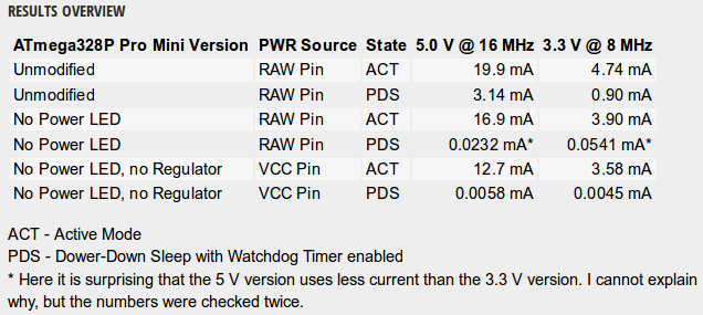
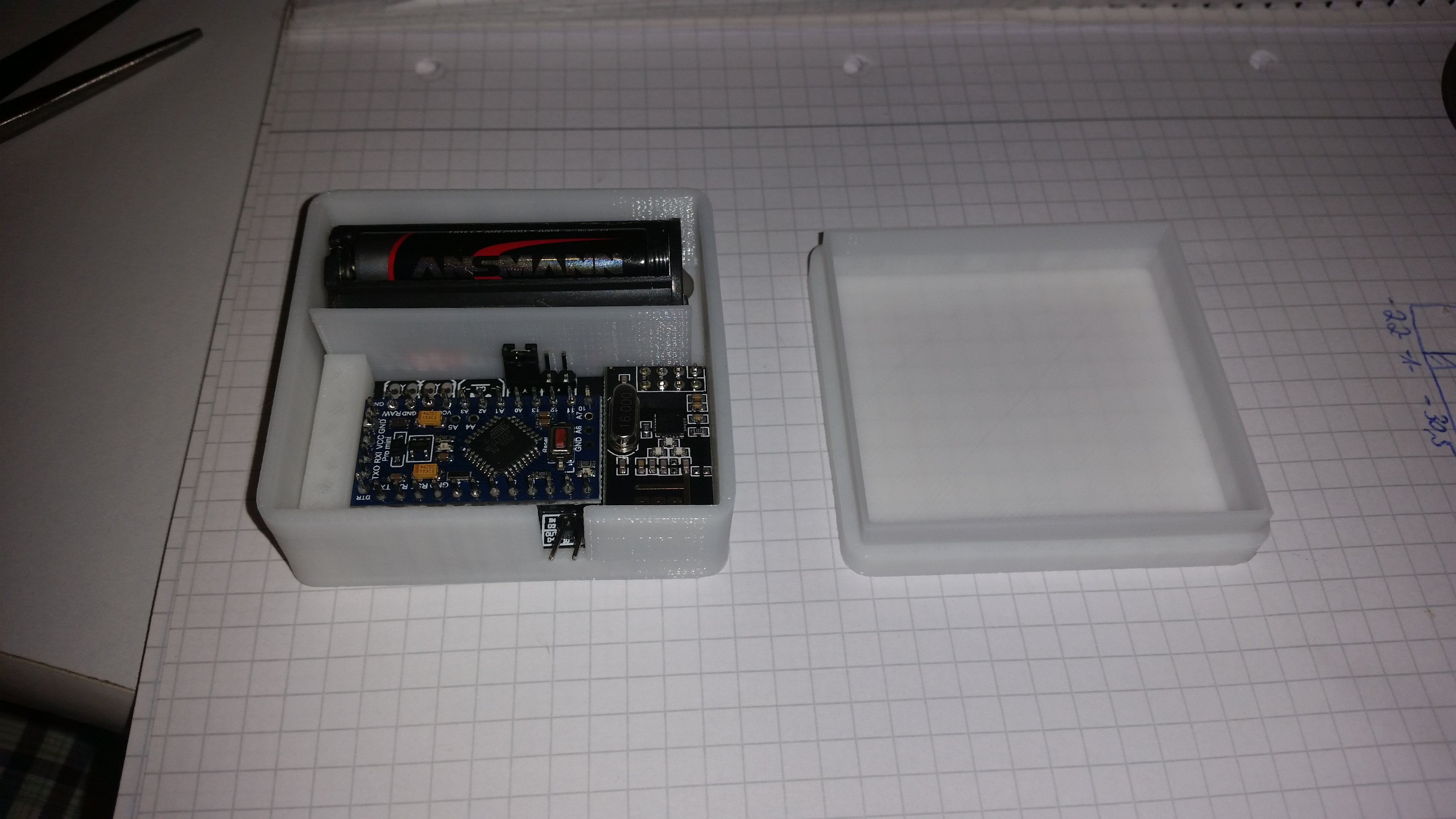
I go on reading your usefull links. Thanks again.Here's my try of mysensorizing a cheap smoke detector, including 3D-printed case:
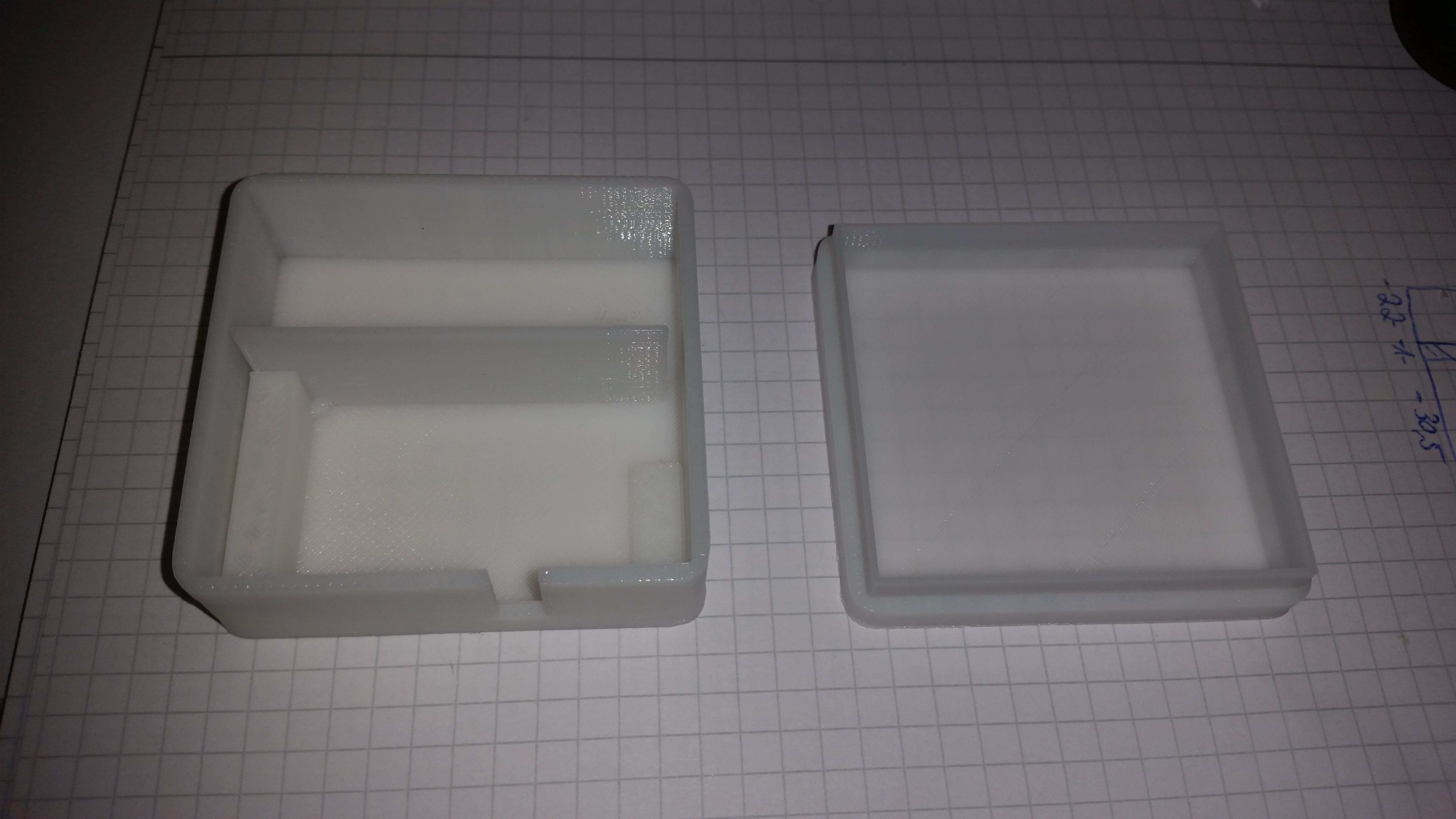
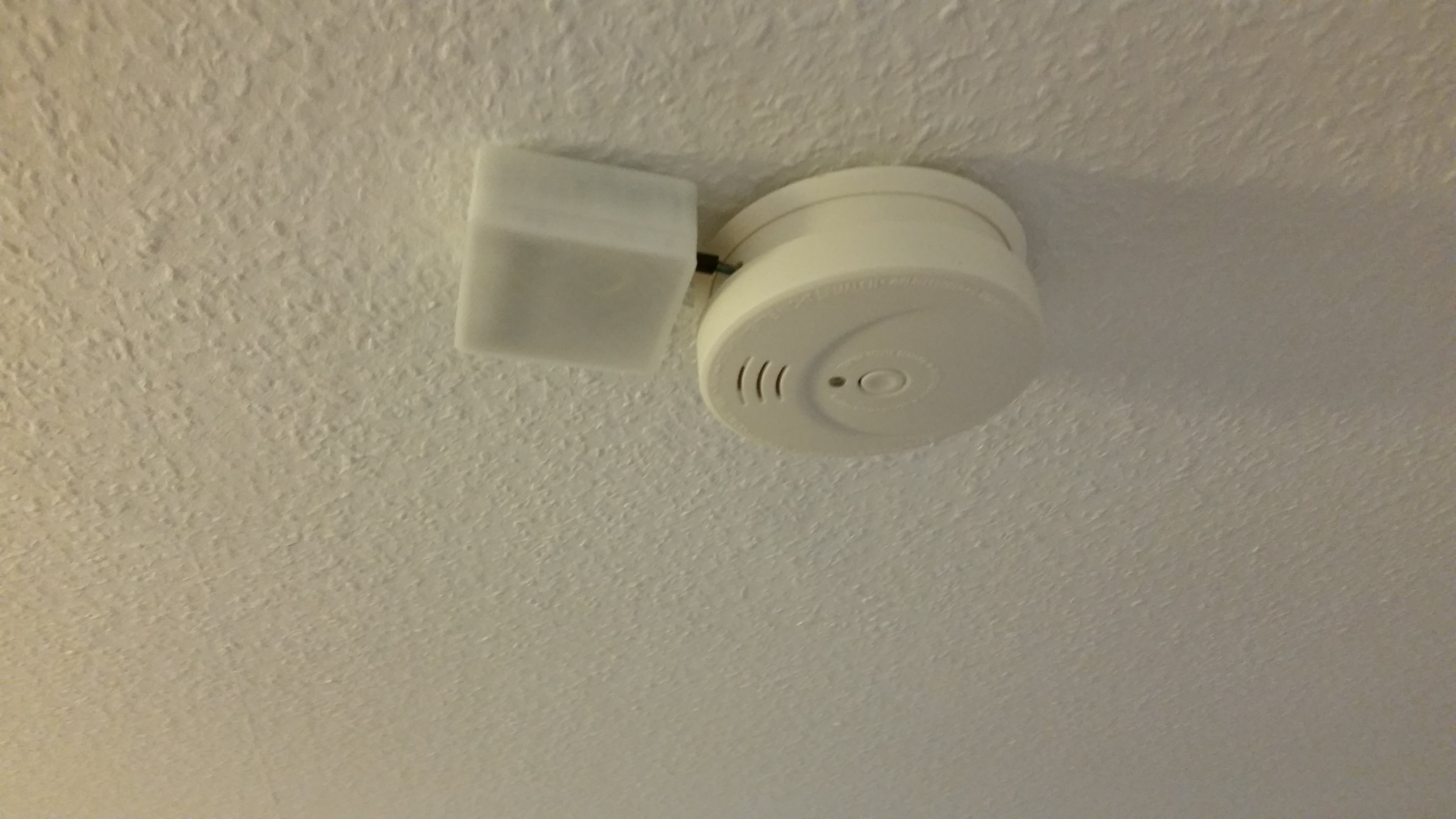
Works flawlessly since 2 months ( I modified 3 smoke detectors at my home)
The designed node can read and trigger the smoke detector. However, it currently runs in read-only mode because of the power issues when the node is active all the time.
The next goal is to use the SmartSleep()-function of MySensors 2.0 with my Controller (OpenHAB), to realize reading&triggering of the smoke detector with a node's battery life of at least 6 months.If anyone knows details on how to implement the SmartSleep-Function, I would really appreciate some information!
-
Nice Work, especially the Box.
Could you give details about the wiring ? How do you read the smoke detector ? On piezo ? -
Nice Work, especially the Box.
Could you give details about the wiring ? How do you read the smoke detector ? On piezo ?@Poupoune1974 said:
Nice Work, especially the Box.
Could you give details about the wiring ? How do you read the smoke detector ? On piezo ?Most cheap smoke detectors use the same microchip as expensive ones, the only difference is that cheap smoke detectors only use certain pins. So I looked up the type number of the microchip in my smokedetector and took a look at the datasheet, which indicates where the I/O (Input/Output) pin of the microchip is located.
When you supply voltage (at least 1V) to this pin, the smoke detector gets triggered - and the other way round: when the smoke detector triggers, it supplies 9v to the pin. So you can solder a wire to this pin and to the GND pin and connect both with your arduino.
Done!
-
Ok, fine, I'll give a try.
Thanks again :-) -
Ok, fine, I'll give a try.
Thanks again :-)@Poupoune1974 said:
Ok, fine, I'll give a try.
Thanks again :-)No problem!
(Don't forget a voltage divider to bring down the signal of the smoke detector to max. 3.3v) -
Here's my try of mysensorizing a cheap smoke detector, including 3D-printed case:
Works flawlessly since 2 months ( I modified 3 smoke detectors at my home)
The designed node can read and trigger the smoke detector. However, it currently runs in read-only mode because of the power issues when the node is active all the time.
The next goal is to use the SmartSleep()-function of MySensors 2.0 with my Controller (OpenHAB), to realize reading&triggering of the smoke detector with a node's battery life of at least 6 months.If anyone knows details on how to implement the SmartSleep-Function, I would really appreciate some information!
@HenryWhite I am trying to implement something similar. Could you post your sketch for this? That would help me. Thanks!
I use an Ei650C that has the two pins ready for the wire connection, but I am not sure how to program the arduino so that it is sleeping and only wakes up on interrupt.
-
Sleep until interrupt: you need this code in the beginning
#define PRIMARY_BUTTON_PIN 2   // Arduino Digital I/O pin for button/reed switch
#define SECONDARY_BUTTON_PIN 3 // Arduino Digital I/O pin for button/reed switch```
And this code where it should sleep
 // Sleep until something happens with the sensor
  sleep(PRIMARY_BUTTON_PIN-2, CHANGE, SECONDARY_BUTTON_PIN-2, CHANGE, 0);
I have take the code snippet from here:
https://github.com/mysensors/MySensors/blob/development/examples/BinarySwitchSleepSensor/BinarySwitchSleepSensor.ino -
Sleep until interrupt: you need this code in the beginning
#define PRIMARY_BUTTON_PIN 2   // Arduino Digital I/O pin for button/reed switch
#define SECONDARY_BUTTON_PIN 3 // Arduino Digital I/O pin for button/reed switch```
And this code where it should sleep
 // Sleep until something happens with the sensor
  sleep(PRIMARY_BUTTON_PIN-2, CHANGE, SECONDARY_BUTTON_PIN-2, CHANGE, 0);
I have take the code snippet from here:
https://github.com/mysensors/MySensors/blob/development/examples/BinarySwitchSleepSensor/BinarySwitchSleepSensor.ino@bjacobse Thanks for the advice. Indeed, looking at the API sometimes helps. :-) But a sketch example is even better.
So, in case of the Ei Electronics 650C it is like this:
It has two pins for connecting wires. I found that terrific -- very simple. :-) So, when there is no Alarm going on, there is 0 V on these two pins. If there is an alarm triggered, there are 5.6 V on the two pins. Sounds ideal. I figure, that I have to put also 5.6 V on these two pins to trigger the alarm from external.But, where do I go from here? I usually use 3.3 V Arduinos. How can I wire this? Does a digital pin of a 3.3 V Arduino take 5.6 V? Or do I need a voltage divider?
Then, I guess I have to connect the + pin to let's say digital pin 3. Because digital pin 2 is used by the radio -- in case we are using interrupts in the future. And the - pin I connect to gnd. Is that right?
Then, I can use the reed switch sketch and try the interrupt thing from the API. Right?
I guess, when I set the 3.3 V Arduino D3 pin to high it will have 3.3 V, right? So I need to figure out if the Ei650C also triggers at 3.3 V. And if so, I would need to check that it is not drawing too much power from the pin. If it does not trigger, what to do? Sounds like using a 5 V Arduino.
How lonng would two AA batteries last if the Arduino was sleeping and the Radio was awake? With 2.0.1 radio interrupt will arrive and power can be saved.
Are the above assumptions correct? Nobody with a ready fire alarm sketch?
Edit: I love this fire alarm. It triggers at 3 V. Perfect. Can't believe it. The good thin about this model that is has one of these 10 year lithium batteries. I like that too.
-
I also use a 3s lipo battery powered a smoke sensor last year, and it works well now.
Hello! It looks like you're interested in this conversation, but you don't have an account yet.
Getting fed up of having to scroll through the same posts each visit? When you register for an account, you'll always come back to exactly where you were before, and choose to be notified of new replies (either via email, or push notification). You'll also be able to save bookmarks and upvote posts to show your appreciation to other community members.
With your input, this post could be even better 💗
Register Login