💬 Insulated Whole House Fan
-
@lis610 sorry, I'm not a place where I can look in depth. It looks like your code isn't communicating with the gateway though. Did you try the line of code above? The device should work with the push button even if it can't communicate with the gateway (with that code).
-
I will come back to the communication issue later.
In your resent code SPI is comment out " //#include <SPI.h> " what is the reason you comment SPI?
The display is not showing anything even with: #define TFT_DISPLAY_ON. and #include <SPI.h> -
I will come back to the communication issue later.
In your resent code SPI is comment out " //#include <SPI.h> " what is the reason you comment SPI?
The display is not showing anything even with: #define TFT_DISPLAY_ON. and #include <SPI.h> -
I will come back to the communication issue later.
In your resent code SPI is comment out " //#include <SPI.h> " what is the reason you comment SPI?
The display is not showing anything even with: #define TFT_DISPLAY_ON. and #include <SPI.h>@lis610 It seems you have two problems.
1 The radio is not connecting reliably with the gateway and may blocking the display from starting.
There are lots of other messages on troubleshooting radio problems.2 The Graphic Display is not operating correctly.
For Item one, You eventually need to resolve the radio problem, However as pete stated in his message if you add the following define it will allow the sketch to run, I can confirm this as i have just tested with just a arduino and just a graphics display.
#define MY_TRANSPORT_WAIT_READY_MS 4000 //This will allow the sensor to function if it can't find the gateway when it first starts upSo if you add this and the display still does not display then you need to test the display connections.
You stated
"Display is working with Adafruit graphicstest example pins:
#define TFT_CS 10 #define TFT_RST 9 #define TFT_DC 8# define TFT_SCLK 13 #define TFT_MOSI 11
I did try the same pins in FAN sketch -nothing on display
Tryed pin# from FAN sketch on Adafruit graphicstest- nothing on display."So with standard connections the display is working.
So you need to test and get the display working with the adafruit test program using the correct pins required for the house fan program.Add the following info the adafruit test sketch as option 3 and comment out the options 1 and 2. Wire the graphic display as per the house fan requirements and it should work.
// Option 3: testing pins used in Whole House Fan Node
#define TFT_CS     3
#define TFT_DC     6
#define TFT_MOSI   7
#define TFT_SCLK   8
#define TFT_RST    0  // you can also connect this to the Arduino reset
                      // in which case, set this #define pin to 0

Adafruit_ST7735 tft = Adafruit_ST7735(TFT_CS, TFT_DC, TFT_MOSI, TFT_SCLK, TFT_RST);
If it does not work the same as when connected to the standard connections , then your wiring is in error and need to be changed to make it work before proceeding to the other sketch.
-
Thank you very much. Star Over. Rewire display and change the code. Never thought I would be excited to see the word ”Error” on display :).
I got five NRF24L01+. Two of them are not working at all. Looks like the one on the gateway working ok, but the node is unstable.
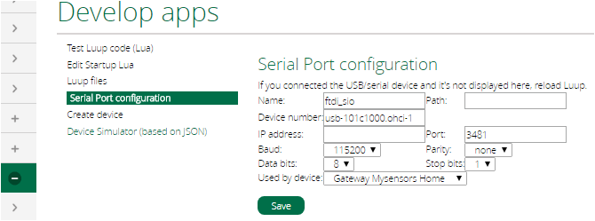
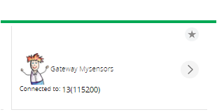
Do I need to create an additional device for Fan in Vera or, it will be displayed within the MySensors serial gateway? -
Thank you very much. Star Over. Rewire display and change the code. Never thought I would be excited to see the word ”Error” on display :).
I got five NRF24L01+. Two of them are not working at all. Looks like the one on the gateway working ok, but the node is unstable.
Do I need to create an additional device for Fan in Vera or, it will be displayed within the MySensors serial gateway?@hard-shovel Thanks for the help.
@lis610 You are picking a very advanced project to start with. If you have the time I'd suggest an easier project like a motion sensor to get started. If you want to keep going I'd suggest doing some additional reading/watching on how this all works. Not trying to be critical but rather save you frustration.
I'm not running UI7 on my Vera so I haven't tested but it should automatically create your device as long as you are including it when first starting the node. For me I press the "Start" button then power up my node (the fan in this case).

However, if you don't have good communication it may not add correctly.
-
Replaced NRF24L01+ and it is working now.
Having trouble with DHT22 it is working on MEGA, but not on Pro Mini ATMega328P 3.3V 8MHz any suggestions@lis610 I find that at 3.3 some of my DHT22s are unreliable and at 3.2V it just gets worse..
The data sheet shows the minimum voltage as being 3.3V, and i suspect my Chinese supplied items are not within specification.
while you are using a 3.3V pro mini do you have a 5V supply for the DHT22?
You will find they are much more reliable at the higher voltage. -
Replaced NRF24L01+ and it is working now.
Having trouble with DHT22 it is working on MEGA, but not on Pro Mini ATMega328P 3.3V 8MHz any suggestions -
I am using 5V power supply and testing sensor with DHT example. DHT is working with MEGA power by 3.3 or 5 v. Maybe it is not working because of Pro Mini 8MHz?
-
I am using 5V power supply and testing sensor with DHT example. DHT is working with MEGA power by 3.3 or 5 v. Maybe it is not working because of Pro Mini 8MHz?
@lis610 DHT22 being a "one wire" protocol, are timing dependent. Make sure that you have defined #define F_CPU 8000000L or have selected the 8mhz option in the newer versions of the IDE. If #define F_CPU gives you an error, you have to do it in the IDE.
Are you using the Adafruit DHT library? Which version? To double check that your CPU frequency is correct, create a new sketch with the following:void setup() { pinMode(13, OUTPUT); } void loop() { digitalWrite(13,HIGH); delay(10000); digitalWrite(13,LOW); delay(10000); }Then time the speed of the blinks. it should be 10 seconds on and 10 seconds off. if you're getting 20 seconds on and 20 seconds off, your F_CPU is wrong.
-
@lis610 you can't just leave us hanging and say "it's working", tell us what the problem was. Was it wiring, was it the 8mhz, was it a wrong library setting, was it a bad sensor? What did you do to make it work? The next person will want to know because they could have the same issue and it teaches the rest of us which troubleshooting tips are working.
-
In the beginning, I connected the DHT sensor to Pro Mini A0 and separate power supply (5V) and ran DHT Example sketch and eading was "nan". Want to mention that all other wires (FAN setup ) attached to Pro Mini as well. Then I disconnect Pro Mini from setup and connect DHT to it (GND, VCC, and A0) got numbers by running DHT Example. Connect everything together (motor, display, radio) and connect DHT to Pro Mini (GND, VCC, and A0) turn on and got zeros for Temp and Hum. Got frustrated and left for a walk. When I come back, Temp: 85 and Hum 52. I was not patient enough. It takes 5 to 6 min for Temp to show on display. I also tried to connect DHT VCC to the external power supply 3.3 and 5 V, but leave GND connected to Pro Mini and it works.