Low power Distance Sensor - Hardware issues
-
Hello @qqlapraline
i want to build exactly this sensor like you do.
Can you help me with a wiring schema and a parts list?Thank you so much!
-
Here is the schematics (freshly made for you :))
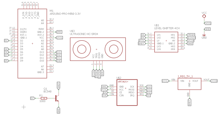
And here the part list:
- Arduino pro mini (3.3v with BOD disabled) or Sensebender Micro
- Ultrasonic sensor: ME007-ULS (available here)
- NRF24L01+ (I use the PA - LNA version for long range communication)
- NPN Transistor: BC548 (the B version if prefered)
- Base resistor: 1k
- 3.3V Step-up Voltage regulator: NCP1402 (available here)
- Logic Level Converter (available here): it says 3.3/5 but actually it's any to any voltage.
- Waterproof case (available here)
And finally here is my code (not cleaned, sorry).
0_1496348693347_DistanceSensebenderMicro.ino
And the Eagle SCH
0_1496348714531_Low power Distance Sensor.schAnd now, I realize that it may have been wise to upload that to openhardware.io :)
Regards,
QQ.
-
Thank you very much!
-
Here is the schematics (freshly made for you :))
And here the part list:
- Arduino pro mini (3.3v with BOD disabled) or Sensebender Micro
- Ultrasonic sensor: ME007-ULS (available here)
- NRF24L01+ (I use the PA - LNA version for long range communication)
- NPN Transistor: BC548 (the B version if prefered)
- Base resistor: 1k
- 3.3V Step-up Voltage regulator: NCP1402 (available here)
- Logic Level Converter (available here): it says 3.3/5 but actually it's any to any voltage.
- Waterproof case (available here)
And finally here is my code (not cleaned, sorry).
0_1496348693347_DistanceSensebenderMicro.ino
And the Eagle SCH
0_1496348714531_Low power Distance Sensor.schAnd now, I realize that it may have been wise to upload that to openhardware.io :)
Regards,
QQ.
-
@qqlapraline would you mind reupload your sketch?
-
Does it work fine ?
In case, you need it, here it goes again :)
0_1504557254355_DistanceSensebenderMicro.ino
Beware, it uses a former version of the MySensors library.QQ.
-
Does it work fine ?
In case, you need it, here it goes again :)
0_1504557254355_DistanceSensebenderMicro.ino
Beware, it uses a former version of the MySensors library.QQ.
@qqlapraline thanks! It works fine, thanks again!
-
I tried this with a similar setup but RFM95 for LoRaWan and without the transistor as I'm testing it directly on USB.
A pololu 5V stepup regulator does not even work directly on VCC - if I connect the HC-SR04, voltage drops from 5V
to 1.2V after the regulator.I then tried a different regulator from aliexpress, this setup works with the regulator on VCC, but if I try to control it through a
Pin, Voltage also drops and does not even power the regulator (it has a LED) :( -
From my experience, the transistor (or mosfet) is key to allow enough current to the DC-DC booster. Otherwise, it will not provide the appropriate voltage because max current getting out of a digital pin from Arduino is around 40 mA.
QQ.
-
I have a working setup now, however, it seems that I lose current through the trigger pin.
If I disconnect it, it drops.@qqlapraline what I don't get is: Do you really have GND on the high side of the LVL converter connected to GND as in your schematic?
Since the GND sides on the converter are connected, this closes the loop for the regulator, thus it would be turned on all the time?
Same for the HC-SR04Thanks!
@chbla well, yes. As the level adapter AND the booster are triggered only when needed (during the measure time), I don't see where it closes the loop.
By maybe I misunderstand something. Where do you loose some current ? The trigger pin from the HC-SR04 ?QQ.
-
What I mean is, those should be connected to GNDT not GND as in your diagram - right?
GND is permanent ground.I noticed I'm losing current through the trigger pin, the cause is apparently that if disconnected, the system is only on VCC.
Since the trigger bin is set to LOW in my previous sketch, it loses current there.But I found out that if I set the trigger pin to HIGH before sleeping, it's fine. My sketch uses 78ua while sleeping. Using a MOSFET at the moment
to switch. -
What I mean is, those should be connected to GNDT not GND as in your diagram - right?
GND is permanent ground.I noticed I'm losing current through the trigger pin, the cause is apparently that if disconnected, the system is only on VCC.
Since the trigger bin is set to LOW in my previous sketch, it loses current there.But I found out that if I set the trigger pin to HIGH before sleeping, it's fine. My sketch uses 78ua while sleeping. Using a MOSFET at the moment
to switch.@chbla, you are right. As mentionned on the schema, it should be connected to GNDT (the triggered GND). And now I do understand your point.
-
@chbla, you are right. As mentionned on the schema, it should be connected to GNDT (the triggered GND). And now I do understand your point.
@qqlapraline good to hear! :) Thanks for the confirmation
-
I need help :( - I have soldered the whole thing to a prototyping board, and now the Pro Mini keeps resetting.
Does anyone see a problem in the following schematic? (sorry for the drawing, I'm a bit limited here).
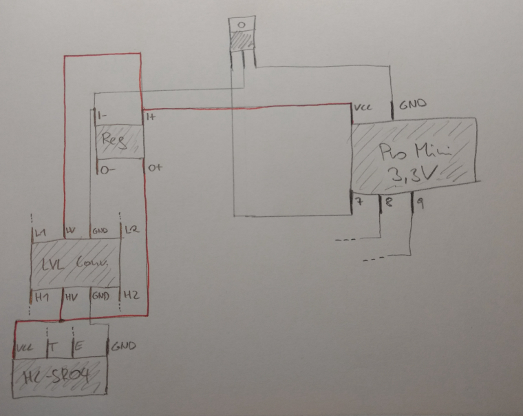
As mentioned I'm using a MOSFET, switched on/off via Pin 7.
Mosfet: https://de.aliexpress.com/item/10PCS-IRLB8721-TO220-IRLB8721PBF-TO-220-free-shipping/32714364118.html?spm=a2g0s.9042311.0.0.FjZdIJ
Vreg: https://de.aliexpress.com/item/2pcs-DC-DC-Power-Supply-Converter-Step-Up-Boost-Module-1A-3V-to-5V/32598574742.html?spm=a2g0s.9042311.0.0.IFPbYZ
Lvl Converter: https://de.aliexpress.com/item/Free-shipping-1pcs-4-channel-IIC-I2C-Logic-Level-Converter-Bi-Directional-Module-5V-to-3/32670479389.html?spm=a2g0s.9042311.0.0.OAwsE9It was working fine on the breadboard, but I have verified all the connections.
Right now it seems to reset all the time (2nd LED blinking on the arduino).
The regulator switches on and off with 1hz, the voltage between I+ and I- changes between 1.0V and 2.4V
If I connect GND to the regulator directly, bridging the Mosfet, it works.Any idea?
-
I need help :( - I have soldered the whole thing to a prototyping board, and now the Pro Mini keeps resetting.
Does anyone see a problem in the following schematic? (sorry for the drawing, I'm a bit limited here).
As mentioned I'm using a MOSFET, switched on/off via Pin 7.
Mosfet: https://de.aliexpress.com/item/10PCS-IRLB8721-TO220-IRLB8721PBF-TO-220-free-shipping/32714364118.html?spm=a2g0s.9042311.0.0.FjZdIJ
Vreg: https://de.aliexpress.com/item/2pcs-DC-DC-Power-Supply-Converter-Step-Up-Boost-Module-1A-3V-to-5V/32598574742.html?spm=a2g0s.9042311.0.0.IFPbYZ
Lvl Converter: https://de.aliexpress.com/item/Free-shipping-1pcs-4-channel-IIC-I2C-Logic-Level-Converter-Bi-Directional-Module-5V-to-3/32670479389.html?spm=a2g0s.9042311.0.0.OAwsE9It was working fine on the breadboard, but I have verified all the connections.
Right now it seems to reset all the time (2nd LED blinking on the arduino).
The regulator switches on and off with 1hz, the voltage between I+ and I- changes between 1.0V and 2.4V
If I connect GND to the regulator directly, bridging the Mosfet, it works.Any idea?
@chbla, I'm quite puzzled.
As it works on the breadboard, of course, I would chase for bad soldering. For instance, the mosfet gate controled by pin 7.Any picture of the arduino pro mini ?
-
@chbla, I'm quite puzzled.
As it works on the breadboard, of course, I would chase for bad soldering. For instance, the mosfet gate controled by pin 7.Any picture of the arduino pro mini ?
@qqlapraline Just use a 5V pro mini and get rid of level converter and mosfet!
Power the 5V HC-SR04 sonar with a pro mini digital pin.
Switch on the sonar for doing a measurement and then switch off again and put the promini to sleep till the next measurement. -
@qqlapraline Just use a 5V pro mini and get rid of level converter and mosfet!
Power the 5V HC-SR04 sonar with a pro mini digital pin.
Switch on the sonar for doing a measurement and then switch off again and put the promini to sleep till the next measurement. -
Great, @peerv !
That's a very good idea.
Do you have reasonable power consumption ?@qqlapraline The 5v and 3v3 pro-minis can both be modified to very similar low power consumption, Google low power pro-mini for a multitude of sites over several years detailing comparatives and examples. I had reason to dig into this as explained below:
With combined radio and RTC on a 3v3 pro-mini I was faced with a lack of available pins from the combination to deal with the 5v ultrasonics as well as providing voltage step-up. I tried a plethora of potential solutions before realising it was a losing battle with a single device and so many demands.
Adding a low power 5v pro-mini to the node to deal with the US and communicating via I2C to the 3v3 pro-mini ended up the most efficient solution for my case. It may seem counter intuitive to waste energy on two devices and two power sources, but not so, both sleep saving energy. In my own case I was going to end up with two devices and two power supplies anyway, but just two separate radio nodes, so there was no energy penalty.
The 5v pro-mini has one interrupt triggered by the 3v3's RTC for US readings, the second interrupt is to be enabled by the adjacent Gas Meter reed sensor, releasing the original dedicated node for other duties.
It is not completed and deployed yet as it is still sub-zero here and the ground is rock solid where the sensor head has to run.