💬 Building a Raspberry Pi Gateway
-
@gohan Sorry I miss your answer a few days ago
I don't want to a gateway with both rfm69 and nrf24..I'm planning to change my nrf24 sensors with rfm69, to have a better transmission distance. My two nodes are outside, and i have communication trouble if i put them where i wanted, specially for my rain gauge.
So I wanted to use those adaptors https://www.openhardware.io/view/16/NRF2RFM69.
I received them, and I'm still waiting RFM69 board to test it.But as the pinout is not the same between nrf24 and rfm69 on raspberry gateway, I could not use the adaptor on the gateway. So before making a new board for my raspberry, I wanted to know if it's possible to change the default pin configuration, to have exactly the same as nrf24, and use an adaptor on the gateway too.
For that, I "just" need to redefine DIO0 on pin 15 (default is 22). So I wonder if it's possible to do it.And "bonus question", I'd like to know why pin configuration is not the same between arduino and raspberry. Why pin 15 is not used for DIO0 on raspberry (equivalent to pin 2 on arduino). I'm telling myself it should be a good reason, but I don't get it.
@barrydou is this what you need (from the documentation and ./configure--help)
--my-rfm69-irq-pin=<PIN> Pin number connected to RFM69 IRQ pin.For the bonus question: I wasn't aware that there was a mapping between Raspberry Pi gpio and Arduino pins. Could you share he rest of the list?
-
@mfalkvidd I don't know what DI00 is, and if it's equivalent to IRQ ? If Yes, it's exactly what I need ! Thank you !!! :) I will test it as soon as I get my RFM69
Here is the pin mapping between RFM69W/NRF24 and Arduino/Raspberry
Arduino mini - NRF24  - RFM69 - Raspberry GW NRF - Raspberry GW RFM
9            - CE     - N/A   - 22               - N/A
10           - CSN/CS - NSS   - 24               - 24
13           - SCK    - SCK   - 23               - 23
11           - MOSI   - MOSI  - 19               - 19
12           - MISO   - MISO  - 21               - 21
2            - IRQ    - DI00  - 15               - 22
So, the only mismatch breaking pin compatibility (and preventing to use adaptors on the raspberry pi gateway) is on IRQ/DI00. Adaptors wire RFM69 DI00 on NRF24 IRQ pin, but they don't use, by default, the same pin on raspberry, depending the radio type.
@barrydou I don't know what dio0 is either, but https://learn.sparkfun.com/tutorials/rfm69hcw-hookup-guide/all describes it like this:
Digital I/O 0
RX interrupt Received data ready interrupt signal from RFM69HCW to microcontrollerwhich sounds like it could be interrupt. It might be worth a try at least.
-
@mfalkvidd Thank you.
I've found that too https://www.mysensors.org/apidocs/RFM69_8h_source.html
It's clearly indicated that DIO0 is IRQ.So I think with "--my-rfm69-irq-pin=" it will do the job.
I'll test it as soon as i'll receive RFM69.
Thank you again
-
@jerseyguy1996 Are you using a decoupling capacitor?
@marceloaqno Sorry to kick this old topic, but I will soon be trying to build my gateway with a Raspberry pi. I was wondering if the capacitor is also required for the gateway, or just for the nodes?
Because at the instruction page on how to wire and build a Raspberry Pi gateway, the capacitor isn't mentioned.
I'll be using a RPI 1 and NRF24L01+
-
Ok, one more question. I thought I read somewhere that the wiring between the RPI and de radio should be as short as possible, but I can't find exactly where I read that anymore.
At another project (zigbee2mqtt) I read that users had better reception when they placed the transceiver further away from the controller, because there was less inteference. So if possible, I would like to use a piece of UTP cable to wire the radio to the raspberry pi. That way I can put the rpi inside a closet, but the radio outside.
So I am not sure if longer wires (say 2, 3 meters) is going to be a problem?
@rolandow there could be a problem.
There are two things to consider.
-
Power drop due to resistance in the cable. See https://electronics.stackexchange.com/questions/113253/voltage-drop-and-safe-current-load-on-cat5-cable for details but use the current used by the radio (provided in the datasheet) instead of the 2.5A used in that question.
-
SPI communication problems due to capacitance in the cable. See https://electronics.stackexchange.com/questions/163468/spi-max-distance for details. See also my post at https://forum.mysensors.org/post/92967 for oscilloscope pictures of what an i2c signal can look like through a long cable. SPI can handle longer cable lengts than i2c though.
-
-
-
For me, my electronics is not as good as my development skills ;-). But I gave it a try. According to the datasheet the NRF24 will consume about 14 mA max. My cable is 2 m max, so then the resistance is 0,16ohms. So if I understand correctly the voltage drop would be 0,00224 volt. Sounds neglegtable to me? Also; can't I just measure the voltage at the end of the cable once it's connected to the RPI?
-
At the stackoverflow page somebody says: "In an answer on a Microchip forum, Jan Axelson, author of 'Serial Port Complete', claims a maximum cable length of 10' for the SPI bus. Other posts have mentioned the same figure.". So 10" is about 3 metres, so I am within that range. I do understand though that this isn't a preferred thing to do.
Which makes me wonder how other people handle this. I mean; I think ideally you'd want the radio that is connected to the controller in the most 'center' way of the home, right? So do people just hange the Pi and the whole shebang to the ceiling? ;-) I'd rather put the controller in the closet where my modem and router are, and then only wire the receiver to outside the closet. Isn't there a better way to do this?
-
-
-
For me, my electronics is not as good as my development skills ;-). But I gave it a try. According to the datasheet the NRF24 will consume about 14 mA max. My cable is 2 m max, so then the resistance is 0,16ohms. So if I understand correctly the voltage drop would be 0,00224 volt. Sounds neglegtable to me? Also; can't I just measure the voltage at the end of the cable once it's connected to the RPI?
-
At the stackoverflow page somebody says: "In an answer on a Microchip forum, Jan Axelson, author of 'Serial Port Complete', claims a maximum cable length of 10' for the SPI bus. Other posts have mentioned the same figure.". So 10" is about 3 metres, so I am within that range. I do understand though that this isn't a preferred thing to do.
Which makes me wonder how other people handle this. I mean; I think ideally you'd want the radio that is connected to the controller in the most 'center' way of the home, right? So do people just hange the Pi and the whole shebang to the ceiling? ;-) I'd rather put the controller in the closet where my modem and router are, and then only wire the receiver to outside the closet. Isn't there a better way to do this?
Nice work @rolandow
You can measure the voltage drop, if you put a load of 14mA on the cable. But without load, there will be no voltage drop.One small adjustment on your calculation: there will be 4m cable (2m to the radio and 2m back). But the drop will still be negligable for a normal nrf24.
-
-
Please edit the image used in this tutorial:
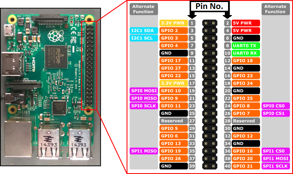
It is wrong and misleading, as it says that pin36 is SPI1 CS0. In fact SPI1 CS0 by default is pin12. To be able to use pin36 as SPI1 CS0 one have to follow implicit steps which can be found on this forum thread: https://www.raspberrypi.org/forums/viewtopic.php?t=203776.
Also it would be useful to add instructions to enable SPI1 in /boot/config.txt to the tutorial. -
I want to run this gateway with another networkid (RFM69) but can't find how to do this. The option --my-rfm69-networkid=105 in the config line is ignored. So maybe it should go in the mysensnsors.conf file, but what is the syntax of this option?
Thanks. -
I want to run this gateway with another networkid (RFM69) but can't find how to do this. The option --my-rfm69-networkid=105 in the config line is ignored. So maybe it should go in the mysensnsors.conf file, but what is the syntax of this option?
Thanks.@rolo6442u where did you find
my-rfm69-networkid? I don't think such an option has ever existed. If you found it somewhere we probably need to update that documentation.Follow the instructions at https://www.mysensors.org/build/raspberry#advanced to set defines.
-
@rolo6442u where did you find
my-rfm69-networkid? I don't think such an option has ever existed. If you found it somewhere we probably need to update that documentation.Follow the instructions at https://www.mysensors.org/build/raspberry#advanced to set defines.
-
@mfalkvidd
I did not found it, I kind of made it up, following the syntax of other options.
Looks like there is no way of changing the ID at this moment for the PI gateway. -
@rolo6442u ok. Well, making things up will usually not add them to the code ;-)
There is a way. Two actually. Set the define in one of the two ways described on the link I provided.
@mfalkvidd
Thanks, will take a look at that. -
Might be nice to know it compilation still seems to works fine on Raspbian Buster on a Raspberry Pi 4.
// Update: unlike on the Pi 3 I now had to activate SPI. Might be good to make that more prominent in the explanation now.
-
Might be nice to know it compilation still seems to works fine on Raspbian Buster on a Raspberry Pi 4.
// Update: unlike on the Pi 3 I now had to activate SPI. Might be good to make that more prominent in the explanation now.
@alowhum to my knowledge, activating SPI has always been required, unless the user has already activated SPI by some other means.
Do you have a suggestion on how to make it more prominent that what it is now? Preferably without contributing too much to the pileup of notices that scare users - everything is super-important to at least 1 person.