ESP8266 Gateway restarts when data is received from node [Solved]
-
After giving on up finding a possible solution for the ESP8266 gateway, I decided to focus on potential issues with the sensors. I added a 4.7uF capacitor to the radios on the gateway and sensor as the troubleshooting thread suggested and it fixed my gateway issues.
-
Yes I have the same Situation. nodeMCU with mysensors 2.0 and ESP8266 board version 2.3.0.
See Article https://forum.mysensors.org/topic/4983/nodemcu-my_gateway_esp8266-and-temp-sensor -
@cravecode
could you tell us which sensors are you using plz ? -
Yes I use one DS18B20.
-
Yes I have the same Situation. nodeMCU with mysensors 2.0 and ESP8266 board version 2.3.0.
See Article https://forum.mysensors.org/topic/4983/nodemcu-my_gateway_esp8266-and-temp-sensor -
@mysensors-6043 said:
Yes I have the same Situation.
No, you have a different situation, we are trying to help you solve it.
Please stick to the original thread you started! -
removed
Not sure what happened before (!)
Just to say I still get this problem - I'm not sure if solved or not - so posting some device configurations for people to try .I found that in situations 1 and 2, the ESP8266 always resets with WDT when the node tries to send a message.(before a message is sent, the ESP8266 is fine - it just waits).
Situation 3 works! - It would be good if someone can confirm if Situation 3 is the intended design ( I also tried uncommenting the LED lines - no difference seen) .-
Situation 1 (Does not work :( ) - 2 devices (Both devices have capacitors added and good power)
Device 1 - Sensor node (Uno with motion sensor - added extra line for device ID)
Device 2 - Gateway (ESP8266 using the "ESP8266 MQTT Gateway" sketch - No changes to code). -
Situation 2 (Does not work :( ) - 2 devices (Both devices have capacitors added and good power)
Device 1 - Sensor node (Uno with motion sensor - added extra line for device ID)
Device 2 - Gateway (ESP8266 using the "gatewayserial" sketch) - No changes to code). -
Situation 3 - (works! :) ) As above, but with a 3rd device
Device 3 - Gateway (Uno with "GatewaySerial" sketch - No change to code
-
-
Not sure what happened before (!)
Just to say I still get this problem - I'm not sure if solved or not - so posting some device configurations for people to try .I found that in situations 1 and 2, the ESP8266 always resets with WDT when the node tries to send a message.(before a message is sent, the ESP8266 is fine - it just waits).
Situation 3 works! - It would be good if someone can confirm if Situation 3 is the intended design ( I also tried uncommenting the LED lines - no difference seen) .-
Situation 1 (Does not work :( ) - 2 devices (Both devices have capacitors added and good power)
Device 1 - Sensor node (Uno with motion sensor - added extra line for device ID)
Device 2 - Gateway (ESP8266 using the "ESP8266 MQTT Gateway" sketch - No changes to code). -
Situation 2 (Does not work :( ) - 2 devices (Both devices have capacitors added and good power)
Device 1 - Sensor node (Uno with motion sensor - added extra line for device ID)
Device 2 - Gateway (ESP8266 using the "gatewayserial" sketch) - No changes to code). -
Situation 3 - (works! :) ) As above, but with a 3rd device
Device 3 - Gateway (Uno with "GatewaySerial" sketch - No change to code
My situation involves 2 devices:
- Device 1 - Gateway (ESP8266 + NRF24L01)
- Device 2 - Temp sensor (NRF24L01 + DHT11)
FYI: I have a 4.7uF capacitor across the GND and VCC pins of the NRF24L01 on both devices.
This may sound silly, but make sure your ESP8266 is booted into the correct mode:
GPIO 0=High
GPIO 2=High
GPIO 15=Low -
-
My situation involves 2 devices:
- Device 1 - Gateway (ESP8266 + NRF24L01)
- Device 2 - Temp sensor (NRF24L01 + DHT11)
FYI: I have a 4.7uF capacitor across the GND and VCC pins of the NRF24L01 on both devices.
This may sound silly, but make sure your ESP8266 is booted into the correct mode:
GPIO 0=High
GPIO 2=High
GPIO 15=LowSUCCESS! - My "ESP8266 MQTT gateway" sketch now works OK - no need for a 3rd device :) :)
*EDIT I've been using this board and the problem is ....I'M USING THE BOARD PICTURED BELOW AND THE LABELS FOR GPIO4 and GPIO5 ARE THE WRONG WAY ROUND (screen print error)
I swapped the cable from the header pin marked GPIO4 to GPIO5 and everything worked fine. I'm wondering if this is the same solution for a lot of people here (I've put this info on build page)
https://github.com/esp8266/Arduino/issues/437
https://twitter.com/bdcatalin/status/663434209265078272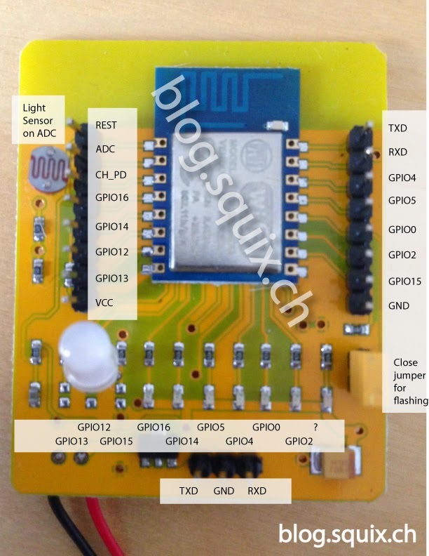
Hope it helps someone
-
-----*removed and put comments above