Minimal design thoughts
-
@tbowmo said:
Seems like dirty pcb is doing a great job, compared to the price, only have experience with prinline.dk from previous jobs, but they are expensive like hell (just looked at their prices earlier today, together with Hek, They want 314$ (plus taxes) for the same job, that I pay 14$ for at dirtypcb, only advantage is that they have a turn arround time of 8 days, instead of 4-5 weeks from dirtypcbs.
Ouch, that seems a bit steep. Never heard of any cheap board houses outside of China. OSHPark may be the exception? I thinks they have fabrication in the US right? I heard they were planning to set up a factory in Europe ... don't know if anything ever happened.
It like a nice tool, Have to look at it :) Only problem is, that I have to generate gerbers myself then, instead of just uploading the eagle file, which dirtypcb turns into gerber files for me. (Remember a project 10 years ago, where it was a lot of work in creating gerbers in eagle).
I don't know how CAM exports have changed over the years but compared to how backwards everything else works in Eagle, exporting Gerbers is easy. DirtyPCBs have a CAM-file listed on their about page. I sent them Gerbers of Meanpenguin's PCB designs and that seemed to have worked out. Knock on wood. Hopefully I'll have the boards back before xmas. The reason I didn't send the Eagle file was their new warning on the front page regarding Eagle v7+ files. Some unspecified problem with their Eagle 6.x installation. Only iffy thing I've run into so far (on some exports) is the drill file showing the holes all over the place because of the wrong precision settings. Now I'm sure the board house would have fixed this for me (their Gerber tools are bound to a great deal more advanced than mine and can probably detect Excellon formats automatically), but choosing EXCELLON_24 as output solved that problem. It's enough to send them impossible routing and endless stop mask errors ;-)
Oh and btw, that Gerber Panelizer also helps to circumvent the 5x5cm limit on freeware Eagle since you can take your Gerbers and join them any way you please as a greater whole. Just to point out the obvious.
@bjornhallberg said:
I don't know how CAM exports have changed over the years but compared to how backwards everything else works in Eagle, exporting Gerbers is easy. DirtyPCBs have a CAM-file listed on their about page. I sent them Gerbers of Meanpenguin's PCB designs and that seemed to have worked out. Knock on wood. Hopefully I'll have the boards back before xmas. The reason I didn't send the Eagle file was their new warning on the front page regarding Eagle v7+ files. Some unspecified problem with their Eagle 6.x installation. Only iffy thing I've run into so far (on some exports) is the drill file showing the holes all over the place because of the wrong precision settings. Now I'm sure the board house would have fixed this for me (their Gerber tools are bound to a great deal more advanced than mine and can probably detect Excellon formats automatically), but choosing EXCELLON_24 as output solved that problem. It's enough to send them impossible routing and endless stop mask errors ;-)
Hhm.. don't tell my boards that dirtypcbs have problems with eagle v7 files :) Haven't seen that warning before now.. So cross my fingers, that everything is ok.
I remember the trouble with excellon format, and getting drill files alligned, but got some files made for printline back then, and they are still making the pcb, so must have done something right :)
Oh and btw, that Gerber Panelizer also helps to circumvent the 5x5cm limit on freeware Eagle since you can take your Gerbers and join them any way you please as a greater whole. Just to point out the obvious.
Think that the free eagle is 10x8cm board space, isn't it?
-
@bjornhallberg said:
I don't know how CAM exports have changed over the years but compared to how backwards everything else works in Eagle, exporting Gerbers is easy. DirtyPCBs have a CAM-file listed on their about page. I sent them Gerbers of Meanpenguin's PCB designs and that seemed to have worked out. Knock on wood. Hopefully I'll have the boards back before xmas. The reason I didn't send the Eagle file was their new warning on the front page regarding Eagle v7+ files. Some unspecified problem with their Eagle 6.x installation. Only iffy thing I've run into so far (on some exports) is the drill file showing the holes all over the place because of the wrong precision settings. Now I'm sure the board house would have fixed this for me (their Gerber tools are bound to a great deal more advanced than mine and can probably detect Excellon formats automatically), but choosing EXCELLON_24 as output solved that problem. It's enough to send them impossible routing and endless stop mask errors ;-)
Hhm.. don't tell my boards that dirtypcbs have problems with eagle v7 files :) Haven't seen that warning before now.. So cross my fingers, that everything is ok.
I remember the trouble with excellon format, and getting drill files alligned, but got some files made for printline back then, and they are still making the pcb, so must have done something right :)
Oh and btw, that Gerber Panelizer also helps to circumvent the 5x5cm limit on freeware Eagle since you can take your Gerbers and join them any way you please as a greater whole. Just to point out the obvious.
Think that the free eagle is 10x8cm board space, isn't it?
@tbowmo Yes you're right, the Eagle board size is 10x8! Don't know where I got the 5x5 from. Nevertheless, since DirtyPCBs can do pretty mindblowing routing at no extra cost and have a pretty good price on 10x10 also ... you could probably save a great deal by doing what the Not Rocket Science guys did and create a heavily panelized board that covers a handful of different PCBs.
-
It will be interesting to see if that radio causes any interference for the MCU. Looks like it will be right over the MCU.?
@ServiceXp said:
It will be interesting to see if that radio causes any interference for the MCU. Looks like it will be right over the MCU.?
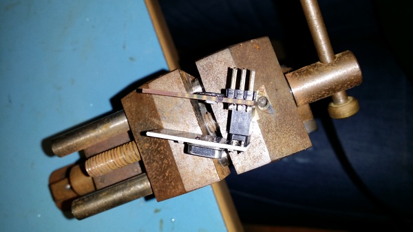
the antenna is not above the mcu, and the nrf module is using the entire backside as gnd. So should be shielded.. Also, I am kind of more worried about mcu generating noise for the radio..
Specially for the first prototype, where I was a bit daft at placing powersupply pins on the wrong side of the pcb, as far away as possible, from the radio. And letting it run under the CPU to pick up noise from that.. Version 2 has this fixed, where I have the power input pins moved closer to the radio, and using wider tracks for VCC arround the board. (Should have done more reviews on the first design before sending it off to dirtypcbs)
-
@ServiceXp said:
It will be interesting to see if that radio causes any interference for the MCU. Looks like it will be right over the MCU.?
the antenna is not above the mcu, and the nrf module is using the entire backside as gnd. So should be shielded.. Also, I am kind of more worried about mcu generating noise for the radio..
Specially for the first prototype, where I was a bit daft at placing powersupply pins on the wrong side of the pcb, as far away as possible, from the radio. And letting it run under the CPU to pick up noise from that.. Version 2 has this fixed, where I have the power input pins moved closer to the radio, and using wider tracks for VCC arround the board. (Should have done more reviews on the first design before sending it off to dirtypcbs)
-
@ServiceXp
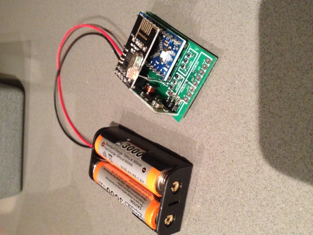
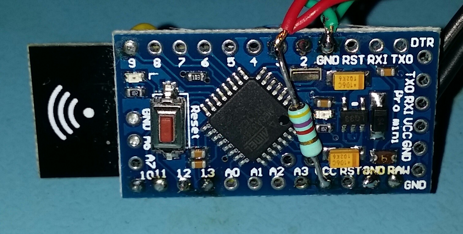
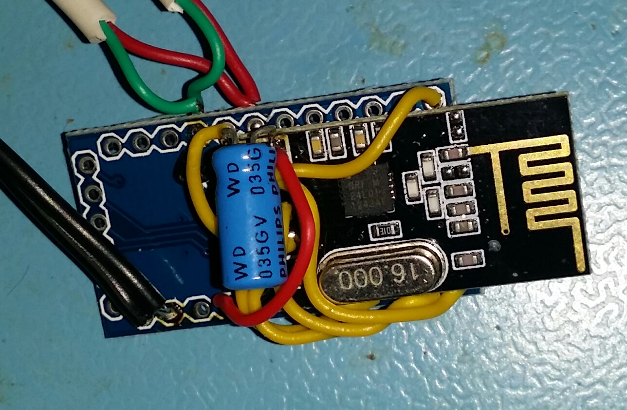
On one of my first mockups, I removed the connector on the radio and used some double sided tape to stick it to the back of an arduino micro, and then soldering wires between the boards. Works like a charm on battery. Antenna is just hanging off the edge of the arduino on the end opposite the serial port pins.
Using it as a range tester for mysensors, logging into a raspberry pi with my mobile using ssh, and then running a serial port terminal emulator on the raspberry to connect to the serial GW. Then I can walk arround with the battery powered node, and check if the GW receives the data packages on my phone :)
Haven't looked at @Bandra's design, but how close is the nrf antenna to the mcu?
-
@ServiceXp
On one of my first mockups, I removed the connector on the radio and used some double sided tape to stick it to the back of an arduino micro, and then soldering wires between the boards. Works like a charm on battery. Antenna is just hanging off the edge of the arduino on the end opposite the serial port pins.
Using it as a range tester for mysensors, logging into a raspberry pi with my mobile using ssh, and then running a serial port terminal emulator on the raspberry to connect to the serial GW. Then I can walk arround with the battery powered node, and check if the GW receives the data packages on my phone :)
Haven't looked at @Bandra's design, but how close is the nrf antenna to the mcu?
-
just ordered components for the first 10 boards. Just about 190$. My wife looked funny at me, as she saw the amount (she was sitting next to me when i ordered).
Well birthay present for myself :)
@tbowmo That was a tad more expensive than you expected I guess? Did Mouser add taxes etc at checkout?
-
Yeah, they added Danish VAT to the order..
Just double checked, it's actually only 154$ (925dkk).. Remembered wrong with the exchange rate when I converted earlier, and just took some numbers from the top of my head. The VAT is around 31$.
But still it's a lot of money, specially this time of year..
-
If use one-sided mounting and on other side set CR2450 holder. Will get a small deviceю
![20141216_175103[1].jpg](/uploads/upload-177cc285-50f8-4b0a-93d4-3232582fe88f.jpg)
-
And now the components arrived :d
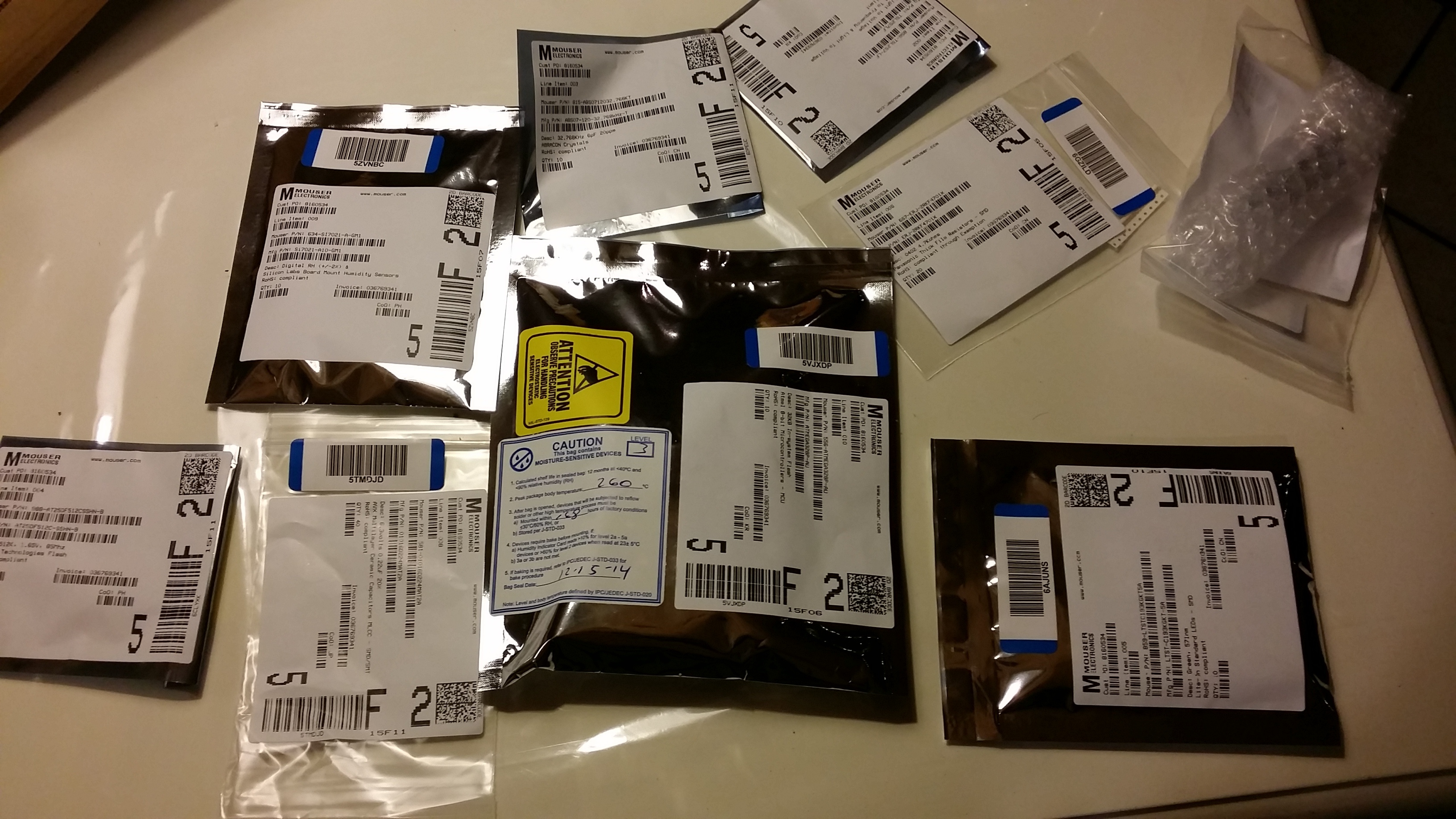
Just miss one capacitor, which is out of stock at Mouser. Got a notice that they will get it in stok again in March 2015! So I'll have to see if I can find an alternative (It was decoupling for the radio).
Hopefully I get some time off to do the first board friday evening.
-
So, it's time for board mounting..
One advice, DOUBLE CHECK the component orders, and TRIPLE check them.. After I got the shipment from mouser, I discovered, that I accidentally had ordered some capacitors in 0101 housing, instead of 0204.. that's DAMN small components.. And I can't use it.. Well thats about 10$ down the drain.. (It was all the decoupling capacitors for the board).
Also found out that I forgot to order a ~100R resistor for the status LED's.. What a bummer!
So I'll have to see if I can source the components quickly from some friends in the next couple of days
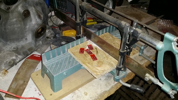
Anyways, pic's from the build:
first depanelling in the "garage"
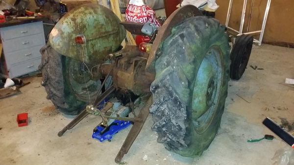
(And just for the fun of it a picture from the garage.. one of my other projects)
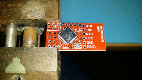
And then to the electronics workshop, mounted the atmega
And with NRF module attached...
-
So, it's time for board mounting..
One advice, DOUBLE CHECK the component orders, and TRIPLE check them.. After I got the shipment from mouser, I discovered, that I accidentally had ordered some capacitors in 0101 housing, instead of 0204.. that's DAMN small components.. And I can't use it.. Well thats about 10$ down the drain.. (It was all the decoupling capacitors for the board).
Also found out that I forgot to order a ~100R resistor for the status LED's.. What a bummer!
So I'll have to see if I can source the components quickly from some friends in the next couple of days
Anyways, pic's from the build:
first depanelling in the "garage"
(And just for the fun of it a picture from the garage.. one of my other projects)
And then to the electronics workshop, mounted the atmega
And with NRF module attached...
@tbowmo Sorry to hear about your sourcing troubles. Wish there was an easier and cheaper way to source things.
Smart depaneling, I have a saw like that standing around as well. I have used it to cut some aluminium profiles before but never considered it for cutting pcbs. Still, I will continue to try and look into tabs and "mouse bites" to make depaneling a bit easier.
Is that an old Ferguson that you're renovating? Sorry, but I immediately thought of Frank Erichsen ;-)
So, no problems hand soldering then? Can you complete the circuit for testing or do the missing components get in the way?
-
Sorry to hear about your sourcing troubles. Wish there was an easier and cheaper way to source things.
I am trying to activate my local nerd network, to see if anyone could get the components within the next couple of days (we are 10-18 nerds having regular meetups, some of them are in the electronics business). One of the nerds have some resistors and caps in 0402, but not exactly the values I want (1uF cap, and 760R resistor if I remember correct)
Smart depaneling, I have a saw like that standing around as well. I have used it to cut some aluminium profiles before but never considered it for cutting pcbs. Still, I will continue to try and look into tabs and "mouse bites" to make depaneling a bit easier.
for the next batch of boards, I might go for easier depanelizing options, with tabs and so on (I got the gerber panelizing tool from http://blog.thisisnotrocketscience.nl/projects/pcb-design-tools/)
So, no problems hand soldering then? Can you complete the circuit for testing or do the missing components get in the way?
I managed the soldering so far.. I must admit that I had forgotten how small 0402 components are :) But soldering, and double checking everything with a "monocle" to magnify things, it's doable..
Also I have tried to power up the atmel, it seems to be ok, at least I can get the correct device checksum when I use my jtagice3 on it with avrdude. It would just be more fun to have all the correct components mounted, for testing and verification of the board, before I push the next board revision off to China
Is that an old Ferguson that you're renovating? Sorry, but I immediately thought of Frank Erichsen wink
Yeah it's an old fergie TEA-20 from '54, that I'm trying to renovate :) Not everything should be computers / electronics :) (Btw. is Frank, or "bonderøven" as he's called in Denmark, also known in Sweden?)
@tbowmo said:
Yeah it's an old fergie TEA-20 from '54, that I'm trying to renovate :) Not everything should be computers / electronics :) (Btw. is Frank, or "bonderøven" as he's called in Denmark, also known in Sweden?)
Yep, bonderøven has been on TV over here for a couple of years now. I think I've seen most episodes. I just love that guy's enthusiasm ... and patience.
-
@tbowmo said:
Yeah it's an old fergie TEA-20 from '54, that I'm trying to renovate :) Not everything should be computers / electronics :) (Btw. is Frank, or "bonderøven" as he's called in Denmark, also known in Sweden?)
Yep, bonderøven has been on TV over here for a couple of years now. I think I've seen most episodes. I just love that guy's enthusiasm ... and patience.
I succeeded in getting a couple of components more (Only missing a 2.2uF 0603 capacitor, that was out of stock at mouser.)
I have vacation, so in theory I could go to the "man cave" and mount the last couple of components. Only problem is, that I have 2 "tasmanian devils" aged 3 and 5 years running wild at home today, So no possibility to have time for my self ;)
-
A quick christmas status update, finaly got arround to power the first board up, just with basic code (blink an LED to check that it will work).
Used a couple of hours trying to get my LED to blink. all other pins would toggle, but not my LED, until I finaly digged into the datasheet. I had used A6 for the LED, which turns out to be an input pin only, facepalm. So the board already have the first "green wire" patch :)
Next up is to get serial up and running. before i can start testing temperature / humidity sensor, and radio interface.