[Solved] NRF24L01+ Serial Gateway not starting ( Sanity check failed )
-
Hello Guys,
i tried to build my first mySensors - Serial Gateway.
It does not seem to work, since the serial monitor gives the following output messages:0;255;3;0;9;Starting gateway (RNNGA-, 2.0.0) 0;255;3;0;9;TSM:INIT 0;255;3;0;9;RF24:write register, reg=0, value=14 0;255;3;0;9;RF24:write register, reg=3, value=3 0;255;3;0;9;RF24:write register, reg=4, value=95 0;255;3;0;9;RF24:write register, reg=5, value=76 0;255;3;0;9;RF24:write register, reg=6, value=35 0;255;3;0;9;RF24:read register, reg=6, value=255 0;255;3;0;9;RF24:read register, reg=5, value=255 0;255;3;0;9;RF24:Sanity check failed: configuration mismatch! Check wiring, replace module or non-P version 0;255;3;0;9;!TSM:RADIO:FAIL 0;255;3;0;9;!TSM:FAILURE 0;255;3;0;9;TSM:PDT 0;255;3;0;9;RF24:write register, reg=0, value=12 0;255;3;0;9;RF24:power downI setup my software like this:
- Download and install Arduino IDE.
- In Arduino IDE, downloaded the MySensors library
- I took the sketch from the example GatewaySerial ( File/Examples/MySensors/GatewaySerial )
- Uploaded the sketch with these 2 additional Defines:
#define MY_NODE_ID 124
#define MY_DEBUG_VERBOSE_RF24
Since i thought the problem could be, that i need a controller to get rid of those error messages, i put the my_node_id to a random value, and to get some more error details i put the verbose_rf24 in the defines.
So the final sketch, that i'm uploading is:
  /**
 * The MySensors Arduino library handles the wireless radio link and protocol
 * between your home built sensors/actuators and HA controller of choice.
 * The sensors forms a self healing radio network with optional repeaters. Each
 * repeater and gateway builds a routing tables in EEPROM which keeps track of the
 * network topology allowing messages to be routed to nodes.
 *
 * Created by Henrik Ekblad <henrik.ekblad@mysensors.org>
 * Copyright (C) 2013-2015 Sensnology AB
 * Full contributor list: https://github.com/mysensors/Arduino/graphs/contributors
 *
 * Documentation: http://www.mysensors.org
 * Support Forum: http://forum.mysensors.org
 *
 * This program is free software; you can redistribute it and/or
 * modify it under the terms of the GNU General Public License
 * version 2 as published by the Free Software Foundation.
 *
 *******************************
 *
 * DESCRIPTION
 * The ArduinoGateway prints data received from sensors on the serial link.
 * The gateway accepts input on seral which will be sent out on radio network.
 *
 * The GW code is designed for Arduino Nano 328p / 16MHz
 *
 * Wire connections (OPTIONAL):
 * - Inclusion button should be connected between digital pin 3 and GND
 * - RX/TX/ERR leds need to be connected between +5V (anode) and digital pin 6/5/4 with resistor 270-330R in a series
 *
 * LEDs (OPTIONAL):
 * - To use the feature, uncomment MY_LEDS_BLINKING_FEATURE in MyConfig.h
 * - RX (green) - blink fast on radio message recieved. In inclusion mode will blink fast only on presentation recieved
 * - TX (yellow) - blink fast on radio message transmitted. In inclusion mode will blink slowly
 * - ERR (red) - fast blink on error during transmission error or recieve crc error
 *
 */

// Enable debug prints to serial monitor
#define MY_DEBUG


// Enable and select radio type attached
#define MY_RADIO_NRF24
//#define MY_RADIO_RFM69

// Set LOW transmit power level as default, if you have an amplified NRF-module and
// power your radio separately with a good regulator you can turn up PA level.
#define MY_RF24_PA_LEVEL RF24_PA_LOW

// Enable serial gateway
#define MY_GATEWAY_SERIAL

// Define a lower baud rate for Arduino's running on 8 MHz (Arduino Pro Mini 3.3V & SenseBender)
#if F_CPU == 8000000L
#define MY_BAUD_RATE 38400
#endif

// Flash leds on rx/tx/err
#define MY_LEDS_BLINKING_FEATURE
// Set blinking period
#define MY_DEFAULT_LED_BLINK_PERIOD 300

// Inverses the behavior of leds
//#define MY_WITH_LEDS_BLINKING_INVERSE

// Enable inclusion mode
#define MY_INCLUSION_MODE_FEATURE
// Enable Inclusion mode button on gateway
#define MY_INCLUSION_BUTTON_FEATURE

// Inverses behavior of inclusion button (if using external pullup)
//#define MY_INCLUSION_BUTTON_EXTERNAL_PULLUP

// Set inclusion mode duration (in seconds)
#define MY_INCLUSION_MODE_DURATION 60
// Digital pin used for inclusion mode button
#define MY_INCLUSION_MODE_BUTTON_PIN  3

// Uncomment to override default HW configurations
//#define MY_DEFAULT_ERR_LED_PIN 4  // Error led pin
//#define MY_DEFAULT_RX_LED_PIN  6  // Receive led pin
//#define MY_DEFAULT_TX_LED_PIN  5  // the PCB, on board LED

#define MY_NODE_ID 124
#define MY_DEBUG_VERBOSE_RF24

#include <SPI.h>
#include <MySensors.h>

void setup() {
  // Setup locally attached sensors
}

void presentation() {
 // Present locally attached sensors
}

void loop() {
    // Send locally attached sensor data here
}
The OS I'm using running arduino IDE:
Windows 10 ( I also tried it with my macbook pro MacOs X, same result. )The Hardware, that I'm using:
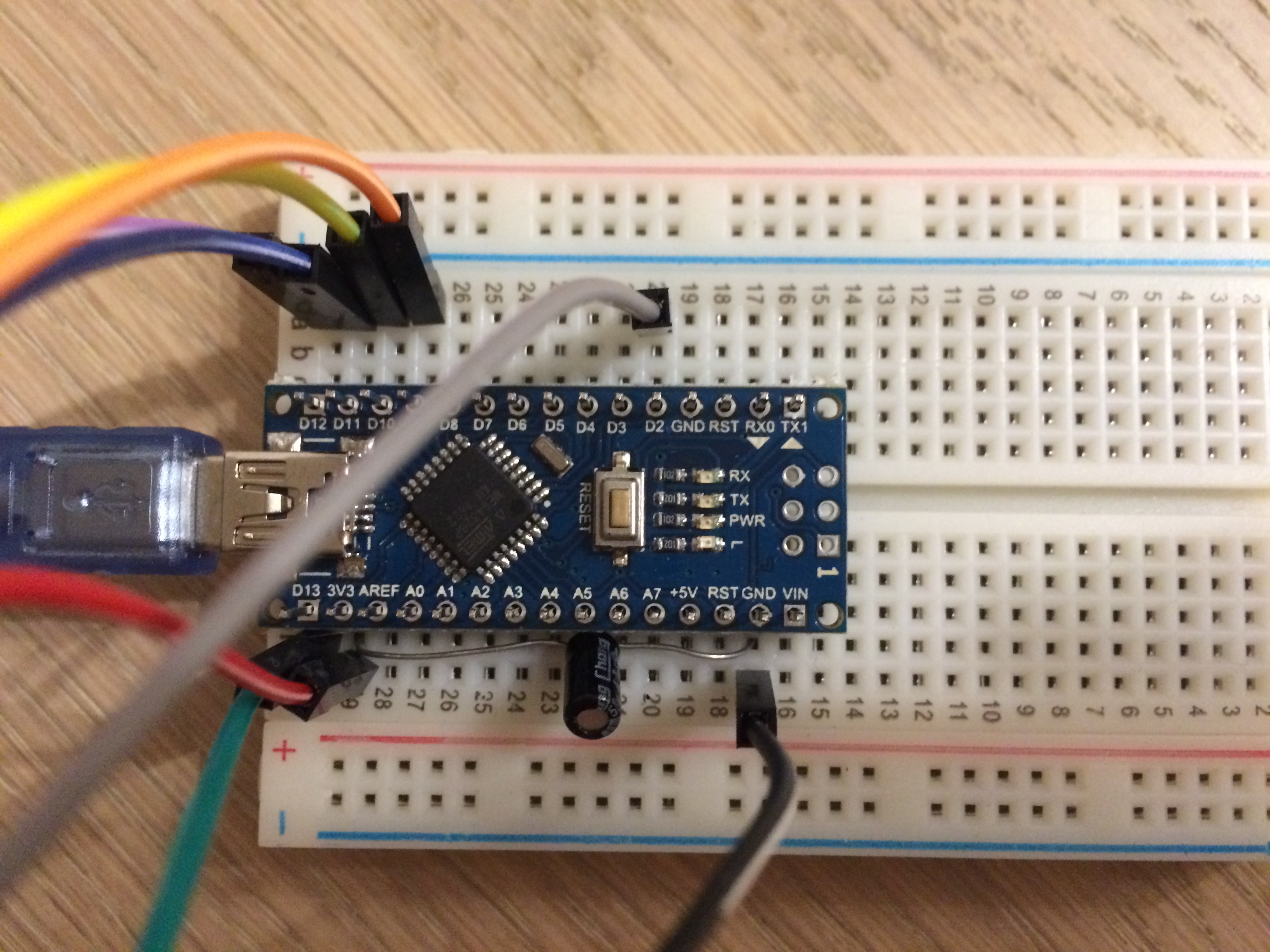
- Arduino Nano with CH340g Chip ( Working without manually installing driver on win10 )
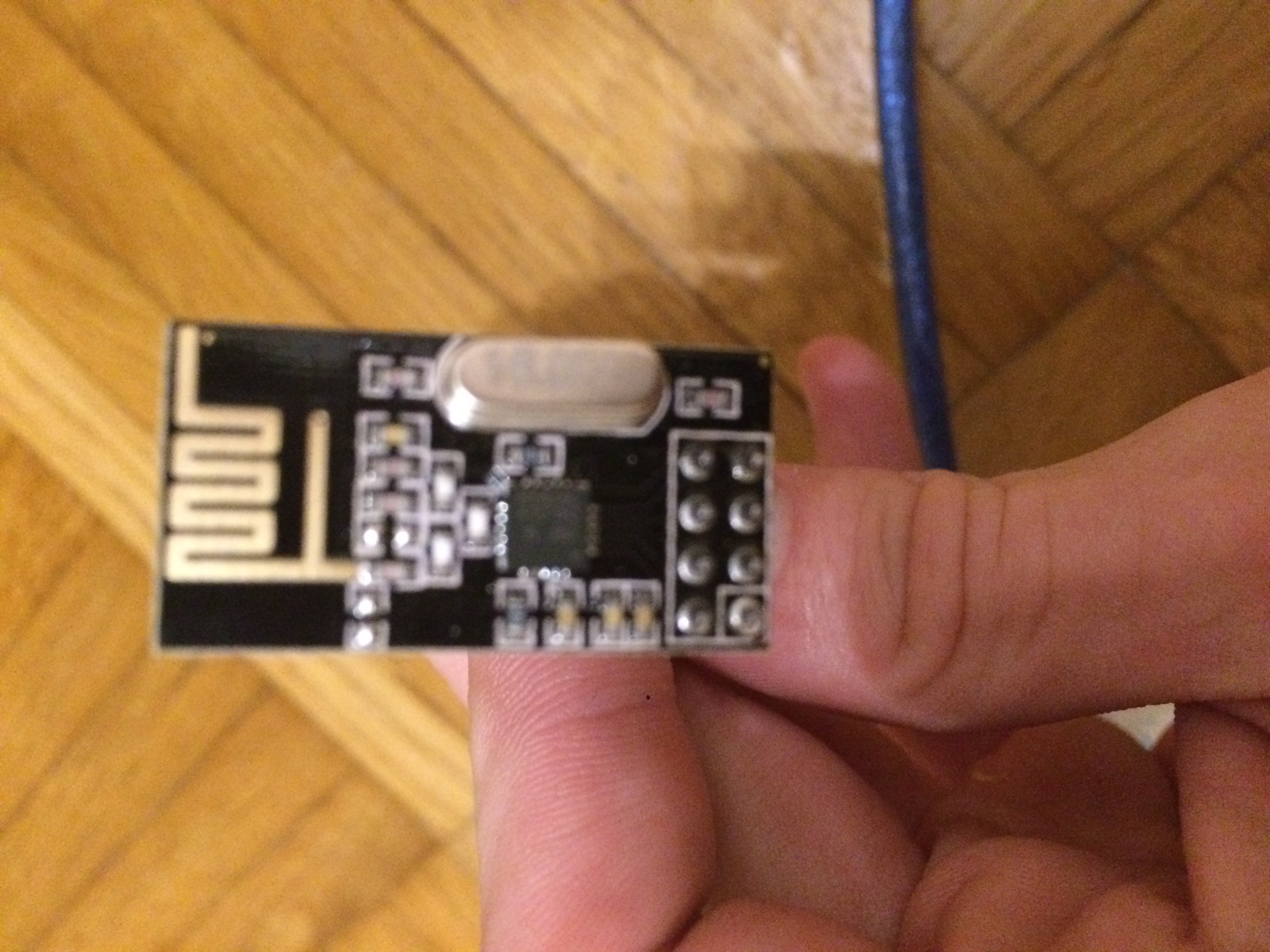
- NRF24L01+, The text on the chip is:
NRF M
24L01+
1452AB
- Capacitor 4.7uF
- Jumper Cables
- Usb - to MicroUsb Cable
- Board
What i tried so far:
- Replacing the NRF24L01+ with ones from a different manufacturer.
- Downloading MySensors API manually from Homepage and copy paste the sample from the MySensors Site.
- Re-wiring all the components.
- Searching forum and google for similar problems.
Sadly, nothing of this helped me so far.
Here's how i wired things up:
Note: For simplicity i used the same colors for my cables as the ones in the exampleArduino:
NRF24L01+:
If you have any ideas what i could have missed, or what i could try to get it working, please let me know.
Thank you in advance. -
Hello.
have you missed to solder pinheaders to your arduino nano ? on the pics it looks like..
That would explain your miswiring error in log.I hope this helps.