💬 RFM69 Serial GW (ATMEGA328P)
-
Hi,
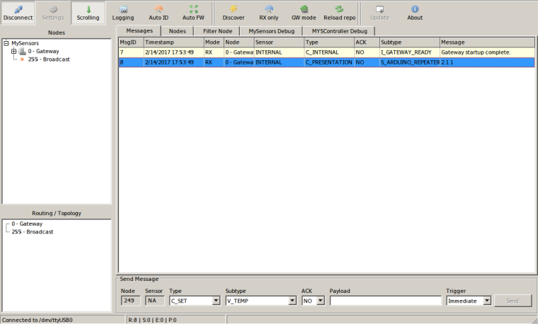
Today I managed to finish this project: hardware assembly and initial serial gw sketch upload and I get I_GATEWAY_READY from serial console so everything seems to be in order. I need to perform some more tests though with some nodes attached and see the messages coming in and out but so far it seems very promising. I didnt' soldered the LEDs yet but that's not so important for now :simple_smile: .
CP2102 usb to serial converter chip working(first line from usb devices listing):
mtiutiu@mtiutiu-H67MA-USB3-B3 ~/Work/AVR_Playground/sensors_network/project/SerialGateway $ lsusb
Bus 002 Device 015: ID 10c4:ea60 Cygnal Integrated Products, Inc. CP210x UART Bridge / myAVR mySmartUSB light
Bus 002 Device 002: ID 8087:0024 Intel Corp. Integrated Rate Matching Hub
Bus 002 Device 001: ID 1d6b:0002 Linux Foundation 2.0 root hub
Bus 004 Device 001: ID 1d6b:0003 Linux Foundation 3.0 root hub
Bus 003 Device 001: ID 1d6b:0002 Linux Foundation 2.0 root hub
Bus 001 Device 005: ID 045e:0779 Microsoft Corp. LifeCam HD-3000
Bus 001 Device 004: ID 1bcf:0005 Sunplus Innovation Technology Inc. Optical Mouse
Bus 001 Device 003: ID 046d:c31c Logitech, Inc. Keyboard K120
Bus 001 Device 002: ID 8087:0024 Intel Corp. Integrated Rate Matching Hub
Bus 001 Device 001: ID 1d6b:0002 Linux Foundation 2.0 root hub
Code uploading using arduino serial bootloader POC:
mtiutiu@mtiutiu-H67MA-USB3-B3 ~/Work/AVR_Playground/sensors_network/project/SerialGateway $ platformio run --target upload
[Tue Feb 14 17:48:38 2017] Processing pro16MHzatmega328 (upload_protocol: arduino, build_flags: -I./lib/MySensors, lib_ignore: MySensors, board_f_cpu: 16000000UL, platform: atmelavr, board: pro16MHzatmega328, framework: arduino)
----------------------------------------------------------------------------------------------------------------------------------------------------------------------------------------------------------------------------------------------
Verbose mode can be enabled via `-v, --verbose` option
Collected 69 compatible libraries
Looking for dependencies...
Library Dependency Graph
|-- <SPI> v1.0
Looking for upload port...
Auto-detected: /dev/ttyUSB0
Uploading .pioenvs/pro16MHzatmega328/firmware.hex

avrdude: AVR device initialized and ready to accept instructions

Reading | ################################################## | 100% 0.00s

avrdude: Device signature = 0x1e950f (probably m328p)
avrdude: reading input file ".pioenvs/pro16MHzatmega328/firmware.hex"
avrdude: writing flash (13122 bytes):

Writing | ################################################## | 100% 3.96s

avrdude: 13122 bytes of flash written
avrdude: verifying flash memory against .pioenvs/pro16MHzatmega328/firmware.hex:
avrdude: load data flash data from input file .pioenvs/pro16MHzatmega328/firmware.hex:
avrdude: input file .pioenvs/pro16MHzatmega328/firmware.hex contains 13122 bytes
avrdude: reading on-chip flash data:

Reading | ################################################## | 100% 3.00s

avrdude: verifying ...
avrdude: 13122 bytes of flash verified

avrdude: safemode: Fuses OK (E:00, H:00, L:00)

avrdude done.  Thank you
MySController serial gw connection and startup ok message:
-
Serial gw is working. Tested with real MySensors nodes and it's working properly. Now regarding stability and such - well...that only time will tell us.
-
Hello, what is the goal of the TXB0104, it's the first time that i see him in a project ?
-
Hello, what is the goal of the TXB0104, it's the first time that i see him in a project ?
It's a logic level voltage converter. The MCU runs at 5V so the logic level voltage that it uses on the SPI port which connects to the RFM69W use 5V too. But the RFM69W module runs at 3.3V and it's not 5V tolerant on its SPI port pins.
The purpose of that IC is to convert voltage levels on the SPI lines forward and backward (from 5V to 3.3V and vice versa) in order to not damage the RFM69W chip.
-
It's a logic level voltage converter. The MCU runs at 5V so the logic level voltage that it uses on the SPI port which connects to the RFM69W use 5V too. But the RFM69W module runs at 3.3V and it's not 5V tolerant on its SPI port pins.
The purpose of that IC is to convert voltage levels on the SPI lines forward and backward (from 5V to 3.3V and vice versa) in order to not damage the RFM69W chip.
@mtiutiu said in 💬 MySensors RFM69W serial GW(ATMEGA328P):
Oh ok, and just for know, why we don't power the atmega with 3.3V ?
-
@mtiutiu said in 💬 MySensors RFM69W serial GW(ATMEGA328P):
Oh ok, and just for know, why we don't power the atmega with 3.3V ?
@tonnerre33
Because at 3.3V the atmega328p mcu can run at max 8MHz as per datasheet. So I wanted it to run at double the speed and for that it needs 5V as per datasheet again. Why at 16MHz? Well because I want the gateway to be more faster in general and to quickly process the incoming messages from the entire radio network. -
Thanks a lot, now i know why ;)
-
Thanks a lot, now i know why ;)
And to use higher baudrates for the serial port on the mcu also. To achieve higher baudrates you need a higher mcu clock frequency too.
-
A fast extraction without traitment if that can help ;)
-
I see C5 on the board has polarity. My ceramic caps seem to have no polarity (no markings on it - https://www.digikey.com/product-detail/en/murata-electronics-north-america/ZRB18AR61E106ME01L/490-10991-1-ND/5321192).
I assume that this is ok and this does not need to be a tantalum cap?Thanks.
-
I see C5 on the board has polarity. My ceramic caps seem to have no polarity (no markings on it - https://www.digikey.com/product-detail/en/murata-electronics-north-america/ZRB18AR61E106ME01L/490-10991-1-ND/5321192).
I assume that this is ok and this does not need to be a tantalum cap?Thanks.
Yes it's ok. Just make sure that you have 10V rated capacitors(this board runs at 5V so it's best to stay above that). On the radio side you can use 6V capacitors as it's powered at 3.3V but anyway...it's easier to use just 10V types instead of remembering what goes where imho.
-
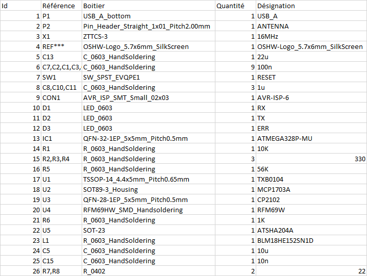
Any BOM? :-)
I still have these PCBs and want to finish em. Can't source a crystal/resonator of about 5x4 mm.The majority of the components are 0603 SMD package type (except 2 smd resistors on the usb lines which are not really mandatory and can be replaced with a solder bridge).
There you go (extracted from schematic - I can't do better than this because it involves more work and I don't have time for it, sorry):
a) 9 x 100nF 0603 SMD MLCC capacitors, X5R/X7R (voltage can be 10V and above)
b) 3 x 1uF 0603 SMD MLCC capacitors, X5R/X7R (voltage can be 10V and above)
c) 1 x 10uF 0603 SMD MLCC capacitor, X5R/X7R (voltage can be 10V and above)
d) 1 x 22uF 0603 SMD MLCC capacitor, X5R/X7R (voltage can be 10V and above)
e) 1 x 10nF 0603 SMD MLCC capacitor, X5R/X7R (voltage can be 10V and above)
f) 1 x ferrite bead 0603 SMD blm18he152sn1d
g) 3 x 330 ohm 0603 SMD resistor
h) 1 x 1Kohm 0603 SMD resistor
i) 1 x 10Kohm 0603 SMD resistor
j) 1 x 56Kohm 0603 SMD resistor
k) 1 x MCP1703A-3302 3.3V/0.25A voltage regulator
l) 1 x TXB0104 voltage level converter
m) 1 x ATMEGA328P-MU AVR MCU (QFN32 package)
n) 1 x CP2102 USB to serial (QFN28 package)
o) 3 x 0603 SMD LEDs (your pick here)
p) 1 x ATSHA204A (SOT-23 package)
q) 1 x RFM69W module (your pick regarding working frequency)
r) 1 x ZTTCS16.00MX ceramic resonator
s) 1 x USB A type male connector for PCB and 1 SMD reset switch (I have no exact links for this, sorry)