Nexa smoke alarm hack
-
Note, I take no responsibilities for modifications you do to your smoke alarm. Use a back up for safety.
I have a few Nexa KD-101Lx smoke detektors with a built in 433MHz radio that just eats batteries so I had the idea to modify them to talk with a simple MySensors node.
The construction is actually a alarm and a radio on the same PCB. Looking at the PCB and a bit of testing I found the connection between the smoke alarm and the radio part.
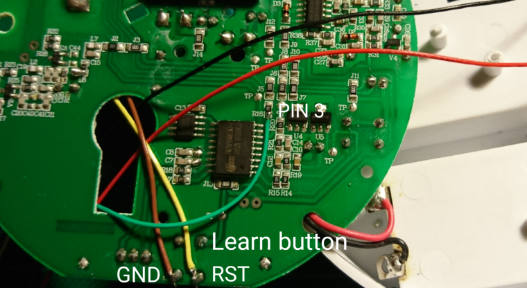
When the alarm triggers the pin is pulled high and since there already is a 10k pull-up resistor in place all that is needed is to add a cable to my sensor. The "learn" button is re-used for triggering reset and providing ground.
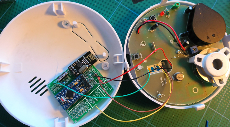
The original radio is powered by 3xAA so I just cut the cable and re-soldered the cables to use only 2xAA's.
I will use the newbiePCB for hooking things up and everything's seems to fit inside the case just fine.
Here is the code that will run for the next couple of days.
/** * The MySensors Arduino library handles the wireless radio link and protocol * between your home built sensors/actuators and HA controller of choice. * The sensors forms a self healing radio network with optional repeaters. Each * repeater and gateway builds a routing tables in EEPROM which keeps track of the * network topology allowing messages to be routed to nodes. * * Created by Henrik Ekblad <henrik.ekblad@mysensors.org> * Copyright (C) 2013-2015 Sensnology AB * Full contributor list: https://github.com/mysensors/Arduino/graphs/contributors * * Documentation: http://www.mysensors.org * Support Forum: http://forum.mysensors.org * * This program is free software; you can redistribute it and/or * modify it under the terms of the GNU General Public License * version 2 as published by the Free Software Foundation. * ******************************* * * DESCRIPTION * * Simple fire alarm example modifying a Nexa KD-101L fire alarm * Connect digitial I/O pin 3 (FIRE_PIN below) with a 10K resistor to GND. * Also connect the FIRE_PIN between the IC and R16 (SMD103=10K). */ // Enable debug prints to serial monitor #define MY_DEBUG // Enable and select radio type attached #define MY_RADIO_NRF24 #include <MySensors.h> #include <Vcc.h> const float VccMin = 2.0*0.6; // Minimum expected Vcc level, in Volts. Example for 2xAA Alkaline. const float VccMax = 2.0*1.5; // Maximum expected Vcc level, in Volts. Example for 2xAA Alkaline. const float VccCorrection = 1.0/1.0; // Measured Vcc by multimeter divided by reported Vcc Vcc vcc(VccCorrection); // Pin connected to the alarm #define FIRE_PIN 3 // Id of the sensor child #define CHILD_ID 0 // Sleep time in ms min s ms unsigned long SLEEP_TIME = 120UL * 60UL * 1000UL; MyMessage msg(CHILD_ID, V_TRIPPED); void setup() { // Setup the alarm pinMode(FIRE_PIN, INPUT); } void presentation() { // Send the sketch version information sendSketchInfo("Fire Alarm", "1.0"); // Register sensor present(CHILD_ID, S_SMOKE, "Alarm tripped", true); // Send the current state //send(msg.set("0")); } void loop() { bool tripped = digitalRead(FIRE_PIN) == HIGH; if(tripped) { Serial.println("Fire!"); send(msg.set(1), true); wait(1000); } else { Serial.println("All ok"); send(msg.set(0), true); // Measure battery level uint8_t batteryPcnt = static_cast<uint8_t>(0.5 + vcc.Read_Perc(VccMin, VccMax)); // Send battery level, used as heartbeat of the sensor sendBatteryLevel(batteryPcnt); } // Sleep until fire sleep(digitalPinToInterrupt(FIRE_PIN), HIGH, SLEEP_TIME); } -
Note, I take no responsibilities for modifications you do to your smoke alarm. Use a back up for safety.
I have a few Nexa KD-101Lx smoke detektors with a built in 433MHz radio that just eats batteries so I had the idea to modify them to talk with a simple MySensors node.
The construction is actually a alarm and a radio on the same PCB. Looking at the PCB and a bit of testing I found the connection between the smoke alarm and the radio part.
When the alarm triggers the pin is pulled high and since there already is a 10k pull-up resistor in place all that is needed is to add a cable to my sensor. The "learn" button is re-used for triggering reset and providing ground.
The original radio is powered by 3xAA so I just cut the cable and re-soldered the cables to use only 2xAA's.
I will use the newbiePCB for hooking things up and everything's seems to fit inside the case just fine.
Here is the code that will run for the next couple of days.
/** * The MySensors Arduino library handles the wireless radio link and protocol * between your home built sensors/actuators and HA controller of choice. * The sensors forms a self healing radio network with optional repeaters. Each * repeater and gateway builds a routing tables in EEPROM which keeps track of the * network topology allowing messages to be routed to nodes. * * Created by Henrik Ekblad <henrik.ekblad@mysensors.org> * Copyright (C) 2013-2015 Sensnology AB * Full contributor list: https://github.com/mysensors/Arduino/graphs/contributors * * Documentation: http://www.mysensors.org * Support Forum: http://forum.mysensors.org * * This program is free software; you can redistribute it and/or * modify it under the terms of the GNU General Public License * version 2 as published by the Free Software Foundation. * ******************************* * * DESCRIPTION * * Simple fire alarm example modifying a Nexa KD-101L fire alarm * Connect digitial I/O pin 3 (FIRE_PIN below) with a 10K resistor to GND. * Also connect the FIRE_PIN between the IC and R16 (SMD103=10K). */ // Enable debug prints to serial monitor #define MY_DEBUG // Enable and select radio type attached #define MY_RADIO_NRF24 #include <MySensors.h> #include <Vcc.h> const float VccMin = 2.0*0.6; // Minimum expected Vcc level, in Volts. Example for 2xAA Alkaline. const float VccMax = 2.0*1.5; // Maximum expected Vcc level, in Volts. Example for 2xAA Alkaline. const float VccCorrection = 1.0/1.0; // Measured Vcc by multimeter divided by reported Vcc Vcc vcc(VccCorrection); // Pin connected to the alarm #define FIRE_PIN 3 // Id of the sensor child #define CHILD_ID 0 // Sleep time in ms min s ms unsigned long SLEEP_TIME = 120UL * 60UL * 1000UL; MyMessage msg(CHILD_ID, V_TRIPPED); void setup() { // Setup the alarm pinMode(FIRE_PIN, INPUT); } void presentation() { // Send the sketch version information sendSketchInfo("Fire Alarm", "1.0"); // Register sensor present(CHILD_ID, S_SMOKE, "Alarm tripped", true); // Send the current state //send(msg.set("0")); } void loop() { bool tripped = digitalRead(FIRE_PIN) == HIGH; if(tripped) { Serial.println("Fire!"); send(msg.set(1), true); wait(1000); } else { Serial.println("All ok"); send(msg.set(0), true); // Measure battery level uint8_t batteryPcnt = static_cast<uint8_t>(0.5 + vcc.Read_Perc(VccMin, VccMax)); // Send battery level, used as heartbeat of the sensor sendBatteryLevel(batteryPcnt); } // Sleep until fire sleep(digitalPinToInterrupt(FIRE_PIN), HIGH, SLEEP_TIME); }@Efflon How is this working out for you?
I have to add a couple of smoke detectors soon and want to do the same thing as you...
Fulltime Servoy Developer
Parttime Moderator MySensors boardI use Domoticz as controller for Z-Wave and MySensors (previously Indigo and OpenHAB).
I have a FABtotum to print cases. -
@Efflon How is this working out for you?
I have to add a couple of smoke detectors soon and want to do the same thing as you...
@marceltrapman It's working just fine except the battery level messages seems to be lost (this happens to all my sensors). Just as a precaution I pushed the test button this morning and got a proper response and a battery level.
-
@marceltrapman It's working just fine except the battery level messages seems to be lost (this happens to all my sensors). Just as a precaution I pushed the test button this morning and got a proper response and a battery level.
@Efflon Nice to know :)
The battery level thing concerns me though.
I would think this is (sort of) essential...Fulltime Servoy Developer
Parttime Moderator MySensors boardI use Domoticz as controller for Z-Wave and MySensors (previously Indigo and OpenHAB).
I have a FABtotum to print cases. -
@Efflon Nice to know :)
The battery level thing concerns me though.
I would think this is (sort of) essential...@marceltrapman Yes, I'll check if adding a ack request will help..
-
@marceltrapman Yes, I'll check if adding a ack request will help..
-
@Efflon Any news? Before I buy a couple of these :)
@marceltrapman Haven't had the time to add an ack to the battery request, but the sensor is working just fine. I don't know if it's my home assistant setup or something else causing the battery levels to get lost but I'm sure it's not part of the smoke alarm hack. Since the sensor drain is almost nothing, the battery levels are not moving much.
I cant guarantee the pcb layout is the same on newer versions of this smoke alarm..
Hello! It looks like you're interested in this conversation, but you don't have an account yet.
Getting fed up of having to scroll through the same posts each visit? When you register for an account, you'll always come back to exactly where you were before, and choose to be notified of new replies (either via email, or push notification). You'll also be able to save bookmarks and upvote posts to show your appreciation to other community members.
With your input, this post could be even better 💗
Register Login