Gas Meter Reading Using a Magnetometer
-
@dpcr Nice adjustment of your Original code. Based on your Original version I have started coding as well as I like the simpleness of just adding a sensor to the meter without taking care of the direct position.
My current code can be found at github via the following link:https://github.com/rspaargaren/Read_Gasmeter/blob/Workinprogress/Read_Gasmeter.ino
Basic differences are:
- I have removed the fram reference but this could be added again if you use it.
- I have added a different setup sequence for fixing the top and bottom. In my case it waits until four changes in direction have occured. So no direct gas flow have to flow after a restart.
- The number of pulses between a change in direction is fixed independent of a change in top or bottom. So in my case every half a cycle will give ten pulses and a full cycle 20 pulses.
- The results are submitted to the gateway after a intervall but also after half a cycle.
- The top and bottom is checked after each cycle. So in case of major difference the interval is changed.
- During normal run, the reading of the y value is executed within the loop. So basically the arduino has time to do some other stuff as well in between the readings.
The code is currently working but requires some clean up. Also I would like to make an option to store the values at the gateway and maybe change the hardware to an ESP version so I can have multiple ways of output. Like MQTT.
This is the current output in Grafana: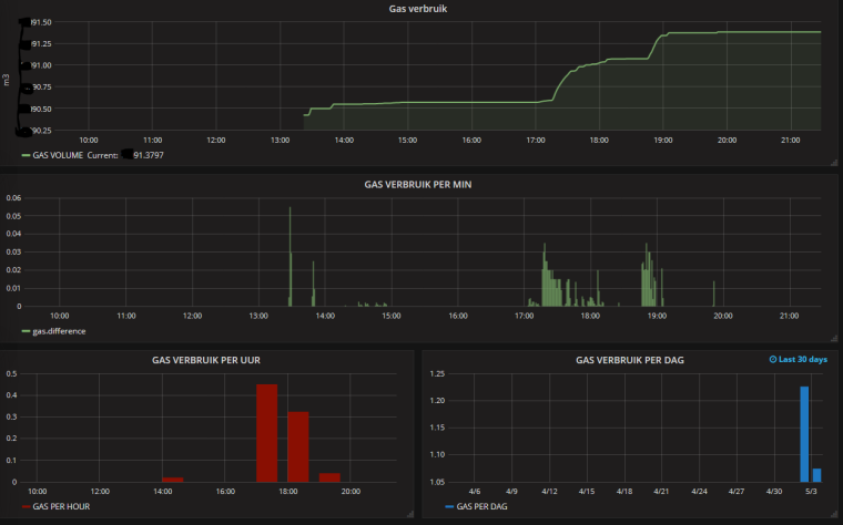
@dynamite Just checking in, how is your set up working? We just had some major problems with too many extra pulses. It looks like something you experienced earlier, we added some smoothing to the readMag output similar to what you have in your sketch and it seems to working fine. Any updates?
-
Hello,
I have a BK-G4L gas meter and I want to build a Mysensor node and measure the gas flow: what is the best solution, a reed switch or a magnetometer?
and for a magnetometer based sensor, do I need HMC5883 or HMC5983?
thanksRaspberrry PI3 - Domoticz
ESP8266 GW - MySensors 2.1.1 -
Hello,
I have a BK-G4L gas meter and I want to build a Mysensor node and measure the gas flow: what is the best solution, a reed switch or a magnetometer?
and for a magnetometer based sensor, do I need HMC5883 or HMC5983?
thanks@jumping Hi I have used the magnetometer. (GY-282 HMC5983)
I these are the +/- of both the systems:
- More easy to locate on your gas meter
- Higher accuracy of output (more pulses per cycle)
- Code is more complex
Read Sensor
- Simple code
- Exact installation from position
- 1 puls per round
-
@dynamite Just checking in, how is your set up working? We just had some major problems with too many extra pulses. It looks like something you experienced earlier, we added some smoothing to the readMag output similar to what you have in your sketch and it seems to working fine. Any updates?
@dpcr Hi, I need to recalibrate to see if the reading is still OK. Somewhere during a total reset I have lost track. But it is on my to do list to get everything up and running again.
As far as I could recollect an overshoot had no influence on my code as the number of pulses for a total cycle is consistent within my code.On the Y reading from the sensor I do have a running average smoothing.
Basically every cycle is splitted into rising and falling part. Each splitted into a fixed number of steps. Based on the current reading of y the number of pulses is calculated within that step. So the amount of pulses within a rise or fall can never be more than the number of steps within that cycle.I am thinking of making the code more simple and only give a pulse on the changes and maybe one in the middle. That would give me about 4 pulses per cycle.
-
@jumping Hi I have used the magnetometer. (GY-282 HMC5983)
I these are the +/- of both the systems:
- More easy to locate on your gas meter
- Higher accuracy of output (more pulses per cycle)
- Code is more complex
Read Sensor
- Simple code
- Exact installation from position
- 1 puls per round
-
@jumping If you have dismissed the possibility of using the authorised reed switch fair enough, but I got the following one, my meter is a BK-G4MT http://store.meterprovida.com/store/category/28/product/metur002.aspx
I have no affiliation with the company, simply a very happy customer, especially at that price. My gas provider was a bit iffy about anything but the dedicated device... -
@zboblamont That is a quite nice price indeed.
@dynamite Indeed, they was stock of the IN-Z61 when I ordered up the V200P water meter and it was too good to turn down. Took a while for the water meter sensor PR6 to come in, but it too was delivered to my daughter who mailed it out to me.
None of it is working yet aside from the physical water meter, busy on other things while the weather is warm such as insulation... -
I was trying to find a way to measure the amount of gas our gas meter was using. I checked out several ways but they all involved using either a hall sensor or a reed switch or a IR sensor or a light sensor. But all of these would not work for my application for a number a reasons. First my meter is outside, second there is no magnet in my meter, third the utility company will not allow us to attach any device to the dials or the electronics of the meter (US smart meter). By the way my meter is a Rockwell 250 (Siemens). So after much researching I'm using a HMC5883L magnetometer. It measures very low magnetic fields.
Please forgive my lack of pictures and links but when I was assembling it I never thought about it. I can get some pictures of the finished sensor if needed.
I found the sweet spot on my gas meter using an Android app on my phone called Sensors Box, which allows one to access the magnetometer inside of the phone. While the gas was flowing I just moved it around over the meter until I found a fluctuation that coincided with the gas flow. This is what I call the "sweet spot". I then built a sensor using the HMC5883L per (https://www.sparkfun.com/tutorials/301). But as of this writing I found that they are no longer making it but do have a replacement (https://www.sparkfun.com/products/retired/10530). I have it successfully connected to my serial gateway and am using Domoticz as a controller.
The initial problem I found was trying to convert the output a the magnetometer to something useful. The data that comes out is stream of numbers from three vectors that goes up and down. After looking at them in the serial plotter of the Arduino IDE I found one vector (y in my case) that looked like a sine wave. Then with a lot of help from my son, who wrote most of the code for the Arduino, it seems to be putting out decent data. However it does need to be fine tuned.
What we ended up doing is auto detecting the top an bottom of the sine wave, then dividing it up into 10 pieces to get useful pulses.
I'm working on getting the Metric and English units out put correct but for now the metric units work OK. Any input is welcome:
UPDATE: 3/12/17 - we have been using the most recent sketch (v.6) and it has been running for two weeks now without a problem. I do plan some updates to the code that I hope will include an interactive serial monitor to set up the sensor for the first use. Also if you have looked at the picture of the sensor it is quite large and I would like to make it a bit smaller.
Does anyone have any idea how to make it smaller yet water proof?
/* * * * * * Currently the autoDetectMaxMin in set to true which will find the TOP and BOTTOM of the wave, however if you want * to use it the gas must be flowing. */ #define MY_DEBUG #define MY_RADIO_NRF24 #include <MySensors.h> #include <Wire.h> //I2C Arduino Library #define CHILD_ID 1 //ID of the sensor child #define SLEEP_MODE false //prevent sensor from sleeping #define address 0x1E //0011110b, I2C 7bit address of HMC5883 int TOP = 0; //highest magnetic field registered from meter (Ga)Initialize low if using AutoDetectMaxMin int BOTTOM = 10000; //lowest magnetic field registered from meter (Ga) Initialize high if using AutoDetectMaxMin int tol = 50; unsigned long SEND_FREQUENCY = 30000; // Minimum time between send (in milliseconds). We don't want to spam the gateway. bool metric = true; //sets units to Metric or English bool autoDetectMaxMin = true; //lets Arduino decide the values for TOP and BOTTOM bool pcReceived = false; //whether or not the gw has sent us a pulse count bool rising = true; //whether or not a pulse has been triggered bool inside = true; //whether the magnetic field is within TOP and BOTTOM limits unsigned long pulsecount = 0; //total number of pulses measured ever unsigned long oldPulseCount = 0; //old total double vpp = metric ? 0.17698 : 0.00625;//Volume of gas per pulse (Rockwell gas meter 250) unsigned long lastSend = 0; //time since last transmission - msec double volume = 0; //Cumulative amount of gas measured const int len = 3; //number of flow rate measurements to save double flow [len]; //array of previous gas flow rate measurements double avgFlow = 0; //average of all elements in flow array double oldAvgFlow = 0; //previous average flow int divider = 1; //Current divider int totDividers = 10; //Number of dividers int increment = (TOP - BOTTOM) / totDividers; //space b/w dividers MyMessage flowMsg(CHILD_ID,V_FLOW); MyMessage volumeMsg(CHILD_ID,V_VOLUME); MyMessage lastCounterMsg(CHILD_ID,V_VAR1); void setup(){ //Initialize Serial and I2C communications Serial.begin(9600); Wire.begin(); // Fetch last known pulse count value from gw request(CHILD_ID, V_VAR1); //Put the HMC5883 IC into the correct operating mode Wire.beginTransmission(address); //open communication with HMC5883 Wire.write(0x02); //select mode register Wire.write(0x00); //continuous measurement mode Wire.endTransmission(); int y = 0; int oldy = 0; //WARNING: MAKE SURE GAS IS RUNNING IF USING THIS OPTION!!! if(autoDetectMaxMin){ //determine max and min magnetic field strength over a few minutes lastSend = millis(); while(millis() - lastSend < 300000){ y = readMag(); if(y > TOP){ TOP = y; //update TOP if new max has been detected } else if(y < BOTTOM){ BOTTOM = y; //update BOTTOM if new min has been detected } } TOP -= tol; //nudge TOP and BOTTOM so that they have a chance of being triggered BOTTOM += tol; increment = (TOP - BOTTOM) / totDividers; //recalculate increment to match new TOP and BOTTOM autoDetectMaxMin = false; //finished determining TOP and BOTTOM } Serial.print("Increment = "); Serial.println(increment); y = readMag(); oldy = readMag(); while(abs(y - oldy) < increment / 2){ //wait until difference b/w y and oldy is greater than half an increment y = readMag(); } rising = (y > oldy); Serial.println(rising ? "Magnetic field is rising" : "Magnetic field is falling"); } void presentation() { // Send the sketch version information to the gateway and Controller sendSketchInfo("Gas Meter", "0.4"); // Register this device as Gas sensor present(CHILD_ID, S_GAS); } void loop(){ if (!pcReceived) { //Last Pulsecount not yet received from controller, request it again request(CHILD_ID, V_VAR1); return; } //detecting magnetic pulses - Fractional Simple Method while(millis() - lastSend < SEND_FREQUENCY){ int y = readMag(); if(inside && rising && y > BOTTOM + divider * increment){ divider++; pulsecount++; } else if(inside && !rising && y < TOP - divider * increment){ divider++; pulsecount++; } if(inside && (y > TOP || y < BOTTOM)){ //switch directions once TOP or BOTTOM divider has been reached inside = false; //keep this from happening multiple times once signal exceeds TOP or BOTTOM Serial.println("OUTSIDE"); } else if(!inside && (y < TOP - increment / 2 && y > BOTTOM + increment / 2)){ rising = !rising; divider = 1; inside = true; Serial.println("INSIDE"); } } //shift all flow array elements to the right by 1, ignore last element for(int idx = len; idx > 0; idx--){ flow[idx] = flow[idx - 1]; } //calculate newest flow reading and store it as first element in flow array flow[0] = (double)(pulsecount - oldPulseCount) * (double)vpp * 60000.0 / (double)SEND_FREQUENCY; //display flow array state Serial.print("Flow Array State: ["); for(int idx = 0; idx < len - 1; idx++){ Serial.print(flow[idx]); Serial.print("|"); } Serial.print(flow[len]); Serial.println("]"); //calculate average flow avgFlow = 0; //reset avgFlow for(int idx = 0; idx < len; idx++){ //calculate sum of all elements in flow array avgFlow += flow[idx]; } avgFlow /= len; //divide by number of elements to get average Serial.print("Average flow: "); //display average flow Serial.println(avgFlow); //send flow message if avgFlow has changed if(avgFlow != oldAvgFlow){ oldAvgFlow = avgFlow; send(flowMsg.set(avgFlow, 2)); } //send updated cumulative pulse count and volume data, if necessary if(pulsecount != oldPulseCount){ oldPulseCount = pulsecount; //update old total //calculate volume volume = (double)oldPulseCount * (double)vpp / 1000.0; //send pulse count and volume data to gw send(lastCounterMsg.set(pulsecount)); send(volumeMsg.set(volume, 3)); } lastSend = millis(); } void receive(const MyMessage &message) { if (message.type==V_VAR1) { unsigned long gwPulseCount=message.getULong(); pulsecount = gwPulseCount; oldPulseCount = pulsecount; Serial.print("Received last pulse count from gw:"); Serial.println(pulsecount); pcReceived = true; lastSend = millis(); } } int readMag(){ int x = 0, y = 0, z = 0; //Tell the HMC5883 where to begin reading data Wire.beginTransmission(address); Wire.write(0x03); //select register 3, X MSB register - was called Wire.send but the compiler had an error and said to rename to to Wire.write Wire.endTransmission(); //Read data from each axis, 2 registers per axis Wire.requestFrom(address, 6); if(6<=Wire.available()){ x = Wire.read()<<8; //X msb x |= Wire.read(); //X lsb z = Wire.read()<<8; //Z msb z |= Wire.read(); //Z lsb y = Wire.read()<<8; //Y msb y |= Wire.read(); //Y lsb } if(!autoDetectMaxMin){ //show real-time magnetic field, pulse count, and pulse count total Serial.print("y: "); Serial.print(y); Serial.print(rising ? " Rising, " : " Falling, "); Serial.print("next pulse at: "); Serial.print(rising ? BOTTOM + divider * increment : TOP - divider * increment); Serial.print(" Current Number of Pulses: "); Serial.print(pulsecount - oldPulseCount); Serial.print(" Last Total Pulse Count Sent to GW: "); Serial.println(oldPulseCount); } else{ //show real-time magnetic field, TOP, BOTTOM, and time left in auto-detect mode Serial.print("y: "); Serial.print(y); Serial.print(" TOP: "); Serial.print(TOP); Serial.print(" BOTTOM: "); Serial.print(BOTTOM); unsigned long remainingTime = 300000 + lastSend - millis(); Serial.print(" Time remaining: "); Serial.print(remainingTime / 60000); Serial.print(":"); remainingTime = (remainingTime % 60000) / 1000; if(remainingTime >= 10){ Serial.println(remainingTime); } else{ Serial.print("0"); Serial.println(remainingTime); } } return y; } -
@dpcr very interesting, I may use some of your sine measuring approach in a powermeter i make.
Nevertheless, i have a question: you say you have no magnet in yr meter, so what is it the magnometer is actually picking up?
@Ed1500 The magnetometer is picking up a change in the magnetic field. Normally the sensor itself is moving and so changes in x,y and z etc can be detected. In case of the gas meter the sensor is stationary but the change in magnetic field due to the rotating magnet on the dial is detected. This will give you a snow wave.
I presume In case no magnet still small changes can be detected due to rotating parts within the meter.
-
@dpcr very interesting, I may use some of your sine measuring approach in a powermeter i make.
Nevertheless, i have a question: you say you have no magnet in yr meter, so what is it the magnometer is actually picking up?
@Ed1500 As Dynamite said, it measures the change in the magnet field produced by the movement inside of the meter. I believe all ferris metals can have some sort of effect as well as an electrical field (something like that produced by an AA battery) on the sensor. There is no magnet in my gas meter (Rockwell 250). I used an app on my phone to determine the best possible location of the sensor. Look at the first post.
-
@dpcr Hi, I need to recalibrate to see if the reading is still OK. Somewhere during a total reset I have lost track. But it is on my to do list to get everything up and running again.
As far as I could recollect an overshoot had no influence on my code as the number of pulses for a total cycle is consistent within my code.On the Y reading from the sensor I do have a running average smoothing.
Basically every cycle is splitted into rising and falling part. Each splitted into a fixed number of steps. Based on the current reading of y the number of pulses is calculated within that step. So the amount of pulses within a rise or fall can never be more than the number of steps within that cycle.I am thinking of making the code more simple and only give a pulse on the changes and maybe one in the middle. That would give me about 4 pulses per cycle.
-
@Ed1500 The magnetometer is picking up a change in the magnetic field. Normally the sensor itself is moving and so changes in x,y and z etc can be detected. In case of the gas meter the sensor is stationary but the change in magnetic field due to the rotating magnet on the dial is detected. This will give you a snow wave.
I presume In case no magnet still small changes can be detected due to rotating parts within the meter.
-
@Ed1500 As Dynamite said, it measures the change in the magnet field produced by the movement inside of the meter. I believe all ferris metals can have some sort of effect as well as an electrical field (something like that produced by an AA battery) on the sensor. There is no magnet in my gas meter (Rockwell 250). I used an app on my phone to determine the best possible location of the sensor. Look at the first post.
@dpcr Thanks, yes i read how you did it with locating the sweet spot, but I was thrown off by the 'no magnet' statement.
'connecting' my meter is also still in the cards, no idea if it has a magnet or not (in which case i may use a Hall sensor), otherwise i may try the magnetometer -
@dpcr Thanks, yes i read how you did it with locating the sweet spot, but I was thrown off by the 'no magnet' statement.
'connecting' my meter is also still in the cards, no idea if it has a magnet or not (in which case i may use a Hall sensor), otherwise i may try the magnetometer -
@Ed1500 Good luck on on your project, keep us updated on your progress. I'm also thinking about trying to measure our electricity consumption using CT's rather than at the meter.
@dpcr thanks, indeed, I am using a CT as well, adding a dc bias, still balancing between just measuring the amplitude of the sinus, or measuring all along the sinus. I think i will have an attiny 25 or ideally an attiny13 do this as a dedicated I2C slave and have that read by an ESP8266. Ofcourse there is the sonoff Touch, but thats a tadd too much to put on a large number of devices.
-
@Ed1500 the ic used in the sonoff pow (HLW8012) costs less than $1 and can do it all for you. Maybe that's an idea...