why no one uses latching relays ?
-
I believe that with latching relay there is also a way to make the relay go into specific state during power outage - with a capacitor that stores some energy, that energy may be used to switch the relay into this specifi state. So I think that latching relays can do all the things non-laching relays can and also more :) and they are much more energy efficient. So my biggest issue is why there is so little of them on the market and hardly no ready made modules with required circuitry to handle them. And they are sooooo expensive ... :(
@rozpruwacz i think your answer is "sooooo expensive", i suspect they are more complicated to build, so even if they were popular they would still cost more. As for the power cost, to put it in perspective, if you use 14w led bulbs, and your automation saves you 1 hour of bulb use, that will run your relay for 28hours at .5w. Now that doesn't help much if you are trying to run the relay on batteries/solar.
-
@gohan yes, they only consume power when making the switch. They don't consume any power to maintain state.
-
Apart from 12V supply voltage, this seems interesting:
http://www.ebay.com/itm/Latching-Bistable-Relay-module-12V-Relay-board-for-AVR-PIC-Arduino-from-EU-/181276052335 -
@Yveaux
I am talking about something like these https://it.aliexpress.com/popular/solid-state-relay-arduino.html . I heven't looked much into them since they have limitations, but I like the fact they are not mechanical.@gohan said in why no one uses latching relays ?:
@Yveaux
I am talking about something like these https://it.aliexpress.com/popular/solid-state-relay-arduino.html . I heven't looked much into them since they have limitations, but I like the fact they are not mechanical.Sorry, I misread your question, as this thread is about latching relays, not solid state.
Solid state relays do consume power, but in general less than mechanical relays.
-
@rozpruwacz i think your answer is "sooooo expensive", i suspect they are more complicated to build, so even if they were popular they would still cost more. As for the power cost, to put it in perspective, if you use 14w led bulbs, and your automation saves you 1 hour of bulb use, that will run your relay for 28hours at .5w. Now that doesn't help much if you are trying to run the relay on batteries/solar.
@wallyllama I agree that there are cases where normal relays are completely fine, but if you want to control some low power device that draws 0.5W then it makes sense to use latching relay, especially if it will be turned on half the time and you have 20 of them.
-
No problem, I brought up the solid state because the opening post was about power consumption of standard relays compared to the latching ones, so I was wondering where they fit in between. That's it. :)
@gohan ssr's require less power to drive them but on the load side they have about 1V drop so this produses power loses, and ssr's that can handle large currents are quite big. But the have other features, like zero crossing switching (they can switch on/off when the voltage sine wave is near 0V).
-
@gohan said in why no one uses latching relays ?:
@Yveaux
I am talking about something like these https://it.aliexpress.com/popular/solid-state-relay-arduino.html . I heven't looked much into them since they have limitations, but I like the fact they are not mechanical.Sorry, I misread your question, as this thread is about latching relays, not solid state.
Solid state relays do consume power, but in general less than mechanical relays.
Why are you all saying they are expensive ? If you take the 12V versions they are just a bit more expensive than normal relays.
@Yveaux said in why no one uses latching relays ?:
Solid state relays do consume power, but in general less than mechanical relays.
I'm sorry but I don't agree with this statement ;)
They consume nearly nothing from the "command" side, but they have a voltage drop. I think it's about 1V on those small Omron (on original one, not the copies sold on Aliexpress which could be worse) so the power loss is up to 2 watts for the 2A they are rated for. On the bigger models visible from the link above you need a (huge) radiator over 4A. -
@rozpruwacz We were talking relay modules (like this one) which normally only take supply and a single control signal.
Having to control the latching of the relay using an H-Bridge I find 'a bit harder' compared to just toggling an IO, regarding both software and hardware.For reference, this is the schematic I use to control a latching relay:
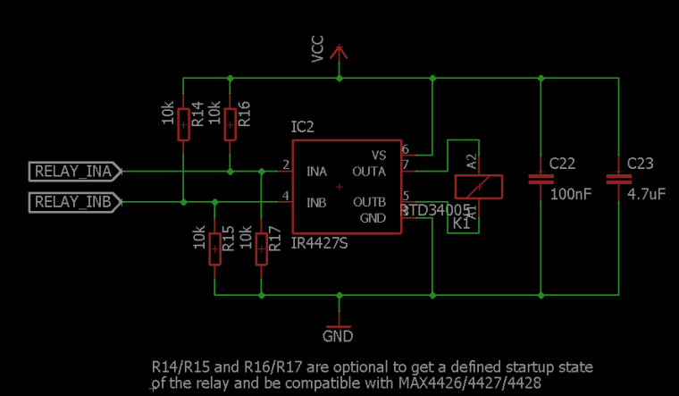
It uses a MAX2226/4427/4428 or compatible MOSFET driver to drive the relay.
And a function to switch it:
#define RELAY_INA_PIN (A0) #define RELAY_INB_PIN (A1) #define RELAY_SET_TIME_MS (30) static void switchRelay( const bool on ) { digitalWrite(RELAY_INA_PIN, on ? LOW : HIGH); digitalWrite(RELAY_INB_PIN, on ? HIGH : LOW); delay(RELAY_SET_TIME_MS); digitalWrite(RELAY_INA_PIN, LOW); digitalWrite(RELAY_INB_PIN, LOW); }You don't necessary need to use an H-Bridge, you can use: (Don't forget the flyback diodes!)
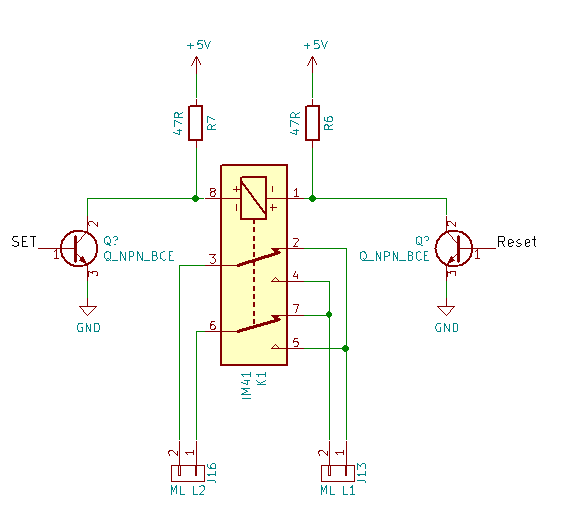
That above schematic is for an intermediate switch in a multi way switching circuit. This way has a high W.A.F (Wife Acceptance Factor). Doing it this way, you can keep the conventional light switches operational. As its part of a multiway light switch circuit, you only need to toggle it to turn the light on or off. You do of course need to detect if the light is on though!
And unless you're mass producing these for sale, what does the extra cost matter?
-
HAHA, You can always get a new wife with lower W.A.T (Wife Acceptance Treshold) :D
-
HAHA, You can always get a new wife with lower W.A.T (Wife Acceptance Treshold) :D
-
HAHA, You can always get a new wife with lower W.A.T (Wife Acceptance Treshold) :D
@rozpruwacz I've invested too much time and money in to this one already!
-
@rozpruwacz
Late to this but for anyone who finds this thread (like I did) with the same thing in mind...here's a relay that looks like it might work for some. (I have not received it yet.)Specifications:
Working voltage: DC 5V
Working current: 70MA
Standby current: 1UA
Load current: AC 250V / 10A, DC 30V / 10A
Trigger mode: Low pulse trigger

There are 10 more listings for what looks like the same product...most about $2 US.
This seems useful for any sort of battery powered node that is to trigger opening or closing a circuit. I certainly would not use it for house lighting in general due to the toggle/uncertain state, storing the state at the node, detecting the relay state when switching, and synchronizing to correct an error seems possible if needed.
My use case is to provide remote control to outdoor landscape lights that use AC line power and a transfer to feed low voltage lighting common in the USA. I have a large yard with 4 different transformers that currently mechanical timer, light sensor, or electrical timer. I'm usually happy to NOT automate dedicated independent simple systems that just work. In this case, my equipment needs fixing after a power outage (mechanical timer), doesn't work well in winter when photo sensors don't get enough light, and I can't turn on the lighting manually very easily. I want to keep these transformers in place as a fallback (in manual 'on' mode), so I could use remote controlled relay to switch the 12 volt AC output to the lighting circuit. I prefer to use battery powered nodes even though line power is available because everything is outdoors and weatherproofing an AC power supply to power a node might be more work.
-
I just came across this thread while doing more research - good stuff!
I do have a latching relay breakout board with 2 latching bistable relays that can switch 16A @ 250VAC
As others have already mentioned, these relays have separate inputs for setting/unsetting the relay, so you can always start off with whatever state you want. Adding a hall effect current sensor, you can also detect the current state of the relay to see if it is open or closed.
You can check it out on Tindie.
Cheers,
Sridhar -
@rozpruwacz
Late to this but for anyone who finds this thread (like I did) with the same thing in mind...here's a relay that looks like it might work for some. (I have not received it yet.)Specifications:
Working voltage: DC 5V
Working current: 70MA
Standby current: 1UA
Load current: AC 250V / 10A, DC 30V / 10A
Trigger mode: Low pulse trigger
There are 10 more listings for what looks like the same product...most about $2 US.
This seems useful for any sort of battery powered node that is to trigger opening or closing a circuit. I certainly would not use it for house lighting in general due to the toggle/uncertain state, storing the state at the node, detecting the relay state when switching, and synchronizing to correct an error seems possible if needed.
My use case is to provide remote control to outdoor landscape lights that use AC line power and a transfer to feed low voltage lighting common in the USA. I have a large yard with 4 different transformers that currently mechanical timer, light sensor, or electrical timer. I'm usually happy to NOT automate dedicated independent simple systems that just work. In this case, my equipment needs fixing after a power outage (mechanical timer), doesn't work well in winter when photo sensors don't get enough light, and I can't turn on the lighting manually very easily. I want to keep these transformers in place as a fallback (in manual 'on' mode), so I could use remote controlled relay to switch the 12 volt AC output to the lighting circuit. I prefer to use battery powered nodes even though line power is available because everything is outdoors and weatherproofing an AC power supply to power a node might be more work.
@grubstake said in why no one uses latching relays ?:
This seems useful for any sort of battery powered node that is to trigger opening or closing a circuit
Be aware that the relay on the board is non latching. Keeping it in actuated state requires continuous power to the relay coil, which will quickly drain batteries.
-
In my use of bistable latching relays, where the state of the relay position is information that must be tracked, I have found it to be easiest to use an optocoupler (H11AA1 or PC817C) to feedback the state of the relay position, which is polled at bootstrap. If you have multiple states to read at boot, you can use something like the TCA9548A multiplexer to accomplish the state read and to set your volatile state variables appropriately, and save on your μC pin count.