Round water tank level sensor
-
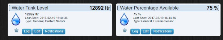
This describes a water tank level sensor for use in a MySensors network. It uses a DYP-ME007Y waterproof ultrasonic sensor to determine the height of water in a round tank. Based on the water height it then works out the amount of water available in litres and also the percentage of water available. Then the results are transmitted via the MySensors network back to the controller.
At this time I have not permanently mounted this node to the tank but in testing it does seem to work ok. I will post back when the whole thing is finished but wanted to share the project so far.
The DYP-ME007Y is a bit fussy about the correct voltage. It needs a good solid 5v supply if you want to get a stable reading. It has a stated range from 30cm to 350cm.
The 30cm minimum may prove a problem in some tanks if you do not have the space above the full water line but it worked out ok for my situation. In testing I could get stable readings down to 25cm but under that it became unreliable.Initially I also had problems with unstable readings once I got over 120cm but this turned out to be caused by a a lack of power while using the USB connection. Once the unit was powered from an external source delivering a good 5v supply the DYP-ME007Y performed within spec.
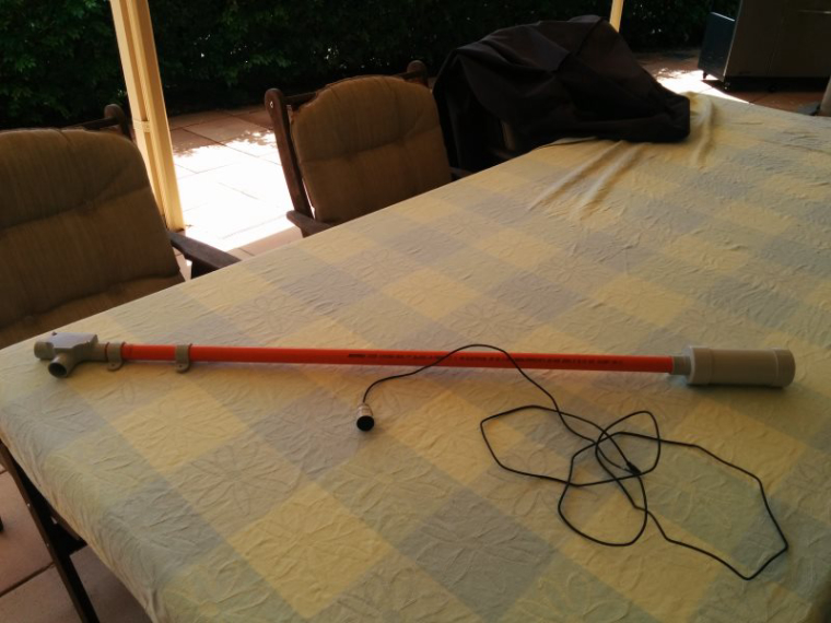
This is a repeater node so I am using a Di-pole antenna on the nrf to increase range. I have found this mod to give good results so is worth the effort if you have room for the leads.The node will be mounted in a round 50mm pvc case. I have several outside nodes using these now, they are very easy to construct, totally rain proof and allow easy access to the arduino for updates etc.
The sketch is running on MySensors V2.1.1
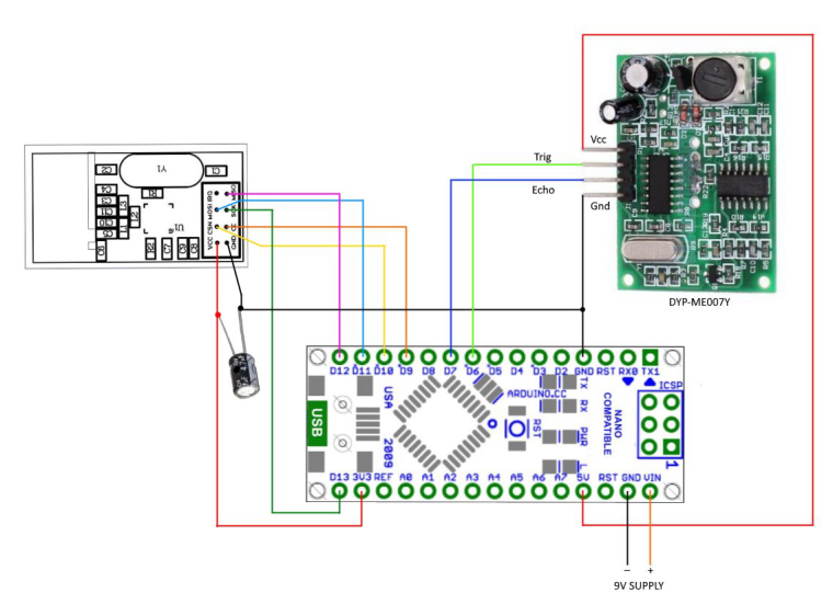
I am using the NewPing library to interact with the DYP-ME007Y
I use sonar.ping_median(5) to take 5 readings and return the median of the results. This will hopefully reduce the amount of incorrect readings.
I also constrain the return from the DYP-ME007Y so the readings stay within the known limits of the tank.
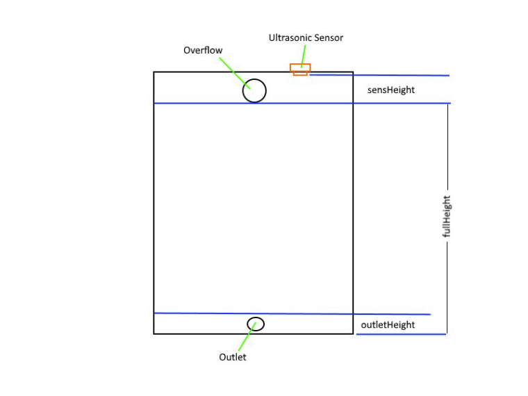
I am using the map function to work out the percentage of water availableThere are a few variables you will need to change to suit your particular tank. Refer to the picture below. All measurements are in cm.
sensHeight: is the distance from the transducer to the height of the water when the tank is full. The full level will usually be the bottom edge of your overflow outlet. Remember with the DYP-ME007Y this has to be at least 25cm.
fullHeight: Is the distance from the bottom of the tank to the level of water when the tank is full.
outletHeight: is the distance from the bottom of the tank to the level you want to be shown as empty. As it is not good for a pump to suck air you would usually make this a comfortable distance above the water outlet.
tankRad: Radius of tank
Sketch:
/*
Sketch to read level of water in a round tank and  then send data back to controller
uses MySensors V2 .

Libraries used
MySensors          https://www.mysensors.org/
NewPing            https://bitbucket.org/teckel12/arduino-new-ping/wiki/Home
SPI                 installed with arduino IDE

*/

// Enable debug prints to serial monitor
#define MY_DEBUG

// Enable and select radio type attached
#define MY_RADIO_NRF24
// Enabled repeater feature for this node
#define MY_REPEATER_FEATURE
// #define MY_NODE_ID 9    // comment out this line if you use dynamic id's
// #define MY_RF24_CHANNEL 84    // channel of nrf network

#include <MySensors.h>
#include <SPI.h>
#include <NewPing.h>


#define CHILD_ID_WATER 1
#define CHILD_ID_PERCENT 2


// newping settings
#define TRIGGER_PIN  6                  // Arduino pin 6 connected to trigger pin on the ultrasonic sensor.
#define ECHO_PIN     7                  // Arduino pin 7 connected to echo pin on the ultrasonic sensor.
#define MAX_DISTANCE 240                // Maximum distance we want to ping for (in centimeters). you should set this to be
                                        // a bit more than fullHeight + sensHeight.

/*------change these to suit your tank setup-----*/
const int tankRad = 170;                // Radius of tank in cm
const int fullHeight = 198;             // Height of water when tank full in cm
const int sensHeight = 30;              // height of sensor above full water mark in cm
const int outletHeight = 7;             // height of water when tank reading will show empty in cm
/*----------------------------------------------*/
unsigned long heartbeatDelay = 120;     // how often the heartbeat will be sent, in minutes
unsigned long lastHeartbeat = millis(); // holder for last time heartbeat was sent
unsigned long waitTime = 6000;          // delay in milliseconds to set time between data readings
unsigned long pingHeight;               // holds total height from ultrasonic sender to current water height
unsigned int waterAvail;                // holds current water available in litres
byte oldWaterPercent;
byte waterPercent = 0 ;                 // used to hold the tank water level percentage

// NewPing setup of pins and maximum distance.
NewPing sonar(TRIGGER_PIN, ECHO_PIN, MAX_DISTANCE);

MyMessage msgVolume(CHILD_ID_WATER, V_LEVEL);              //water availble in liters
MyMessage msgPercent(CHILD_ID_PERCENT, V_LEVEL);           // water percentsge available

void setup() {

}


void presentation()  {
  // Send the sketch version information to the gateway and Controller
  sendSketchInfo("Tank Level", "1.0");

  // Register all sensors to gateway (they will be created as child devices)
  present(CHILD_ID_WATER, S_DUST,"Water Available");
  present(CHILD_ID_PERCENT, S_DUST,"Water Percentage Available");
}


 void loop()
 {


   data_calc();      // perform calculations to get water remaining etc.


  if(oldWaterPercent != waterPercent) {         //check to see if new water data is available
  send(msgVolume.set(waterAvail));
  send(msgPercent.set(waterPercent));
  oldWaterPercent = waterPercent;
  }

  heartbeatCheck();                                    // call heartbeat function

  wait(waitTime);  //Wait then back to loop

}

/*-------------------------start of functions-------------------*/

void heartbeatCheck(){
unsigned long millisNow = millis();           // get the current time
if ((millisNow - lastHeartbeat) > (heartbeatDelay*60000)) {
  sendHeartbeat();
  wait(5);
 // sendBatteryLevel(100);
  lastHeartbeat = millis();
  #ifdef MY_DEBUG
    Serial.println("Heartbeat Sent" );
  #endif
}
}

 void data_calc() {
 pingHeight = sonar.ping_median(5);             //- Do multiple (5) pings and return median
 pingHeight = sonar.convert_cm(pingHeight);     // then convert to cm
 #ifdef MY_DEBUG
  Serial.print("Ping Height raw in cm: ");
  Serial.println(pingHeight);
 #endif
 pingHeight  = constrain(pingHeight, sensHeight, (fullHeight-outletHeight)+sensHeight);     // keep pingHeight within the expected values
 waterPercent = map(pingHeight,sensHeight,(fullHeight-outletHeight)+sensHeight,100,0);           // calculate the percentage of water available
 waterAvail = PI* pow(tankRad,2)*(((fullHeight-outletHeight)+sensHeight)-pingHeight)/1000;    // calculate water available in litres

// Write some debug info
  #ifdef MY_DEBUG
    Serial.print("Ping Height constrained in cm: ");
    Serial.println(pingHeight);
    Serial.print("Percentage Available: ");
    Serial.println(waterPercent);
    Serial.print("Litres Available: ");
    Serial.println(waterAvail);
  #endif
 }
It might look a bit strange that i have used the dust sensor for the MySensors data but (in Domoticz at least) they allow for the best visualisation I think.
Wiring:
All the parts are mounted on a small prototype board. I cut away the board behind the antenna to allow for better reception. I also had to re-position the socket for the transducer to allow it all to fit in the tube.
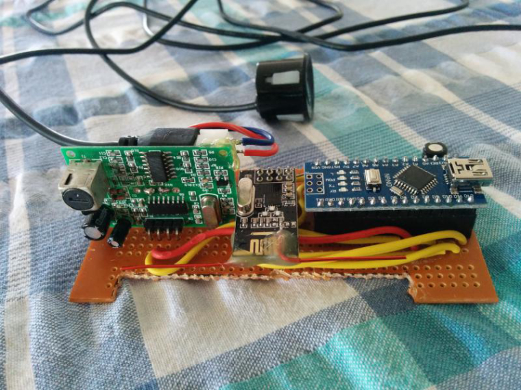
The board is then slid inside the tube
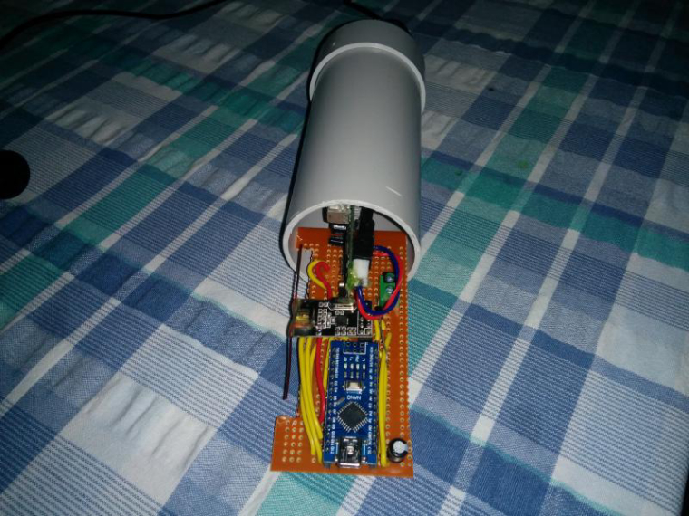
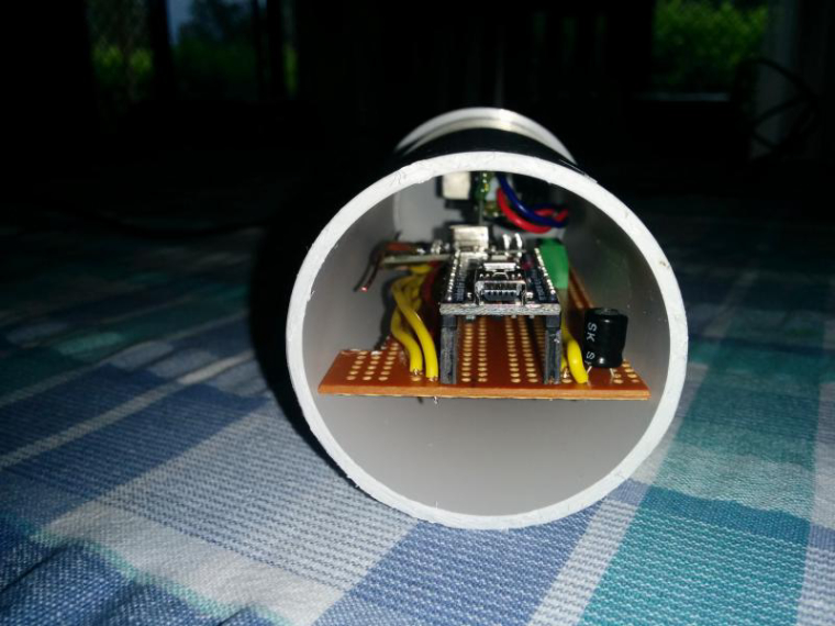
The bottom cap is glued on to prevent moisture from entering but the top is just pressed on to allow easy access when needed. The arduino is positioned at the top so I can quickly connect a serial lead with the cap off. A water proof gland is used at the bottom for the power and transducer cables.
-
Nearly got it all mounted today. Just got to cut a hole in the tank now for the transducer.
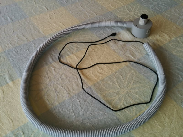
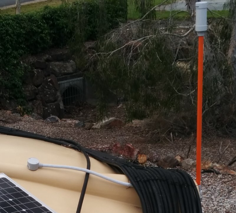
The tank is on a lower level than my lightning sensor node (which is the repeater this node must use) so I ended up mounting it on a 900mm long piece of 25mm conduit. It worked out ok with the node mounted on top all the cabling is now running inside and protected from the elements.
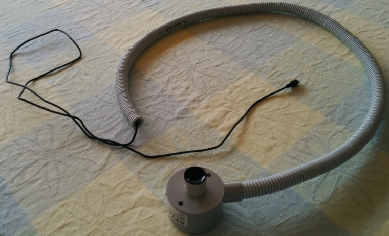
The transducer and its cabling are all enclosed as well
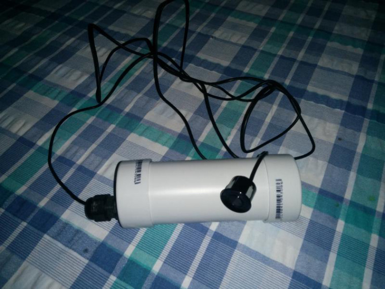
The node assembly
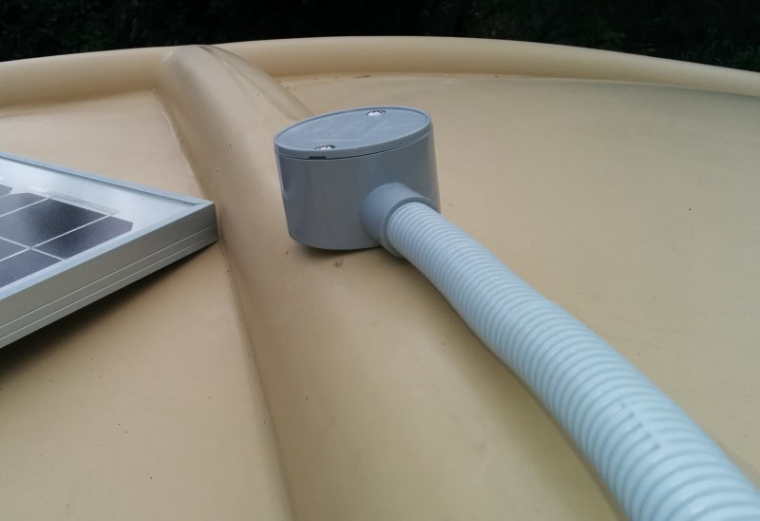
And finally mounted on the tank
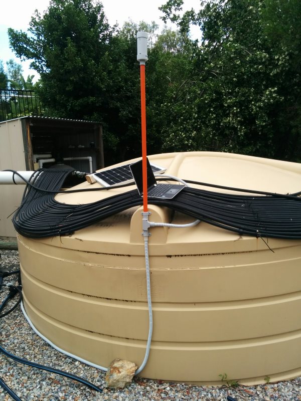
My poor old water tank is about to enter the 21st century!
-
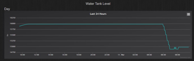
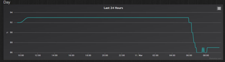
The sensor has bee running for a week now and it is performing well. Readings are fairly consistent and well within my expectations for the cheap ultrasonic sensor used and my needs for this tank.
You can see from the logs it shows a steady level when the water is static and a good picture of water use as the level drops.
I have tweaked the sketch a bit now that i have had a chance to see it in place. Nothing major just a change to the heartbeat and timing.
The sensor now checks the level every 15 seconds and reports immediately if there is a level change. If no change is detected after 15min it sends the data anyway. I have removed the send heartbeat as it is really no longer needed.
/* Sketch to read level of water in a round tank and then send data back to controller uses MySensors V2 . Libraries used MySensors https://www.mysensors.org/ NewPing https://bitbucket.org/teckel12/arduino-new-ping/wiki/Home SPI installed with arduino IDE */ // Enable debug prints to serial monitor #define MY_DEBUG // Enable and select radio type attached #define MY_RADIO_NRF24 // Enabled repeater feature for this node #define MY_REPEATER_FEATURE #define MY_NODE_ID 9 // comment out this line if you use dynamic id's #define MY_RF24_CHANNEL 84 // channel of nrf network #include <MySensors.h> #include <SPI.h> #include <NewPing.h> #define CHILD_ID_WATER 1 #define CHILD_ID_PERCENT 2 // newping settings #define TRIGGER_PIN 6 // Arduino pin 6 connected to trigger pin on the ultrasonic sensor. #define ECHO_PIN 7 // Arduino pin 7 connected to echo pin on the ultrasonic sensor. #define MAX_DISTANCE 240 // Maximum distance we want to ping for (in centimeters). you should set this to be // a bit more than fullHeight + sensHeight. /*------change these to suit your tank setup-----*/ const int tankRad = 170; // Radius of tank in cm const int fullHeight = 198; // Height of water when tank full in cm const int sensHeight = 30; // height of sensor above full water mark in cm const int outletHeight = 7; // height of water when tank reading will show empty in cm /*----------------------------------------------*/ unsigned long lastSent; unsigned long heartbeatDelay = 15; // how often the heartbeat will be sent, in minutes //unsigned long lastHeartbeat = millis(); // holder for last time heartbeat was sent unsigned long waitTime = 15000; // delay in milliseconds to set time between data readings unsigned long pingHeight; // holds total height from ultrasonic sender to current water height unsigned int waterAvail; // holds current water available in litres byte oldWaterPercent; byte waterPercent = 0 ; // used to hold the tank water level percentage // NewPing setup of pins and maximum distance. NewPing sonar(TRIGGER_PIN, ECHO_PIN, MAX_DISTANCE); MyMessage msgVolume(CHILD_ID_WATER, V_LEVEL); //water availble in liters MyMessage msgPercent(CHILD_ID_PERCENT, V_LEVEL); // water percentsge available void setup() { } void presentation() { // Send the sketch version information to the gateway and Controller sendSketchInfo("Tank Level", "1.4"); // Register all sensors to gateway (they will be created as child devices) present(CHILD_ID_WATER, S_DUST,"Water Available"); present(CHILD_ID_PERCENT, S_DUST,"Water Percentage Available"); } void loop() { data_calc(); // perform calculations to get water remaining etc. if(oldWaterPercent != waterPercent) { //check to see if new water data is available send(msgVolume.set(waterAvail)); send(msgPercent.set(waterPercent)); oldWaterPercent = waterPercent; lastSent = millis(); } heartbeatCheck(); // call heartbeat function wait(waitTime); //Wait then back to loop } /*-------------------------start of functions-------------------*/ void heartbeatCheck(){ unsigned long millisNow = millis(); // get the current time if ((millisNow - lastSent) > (heartbeatDelay*60000)) { send(msgVolume.set(waterAvail)); send(msgPercent.set(waterPercent)); lastSent = millisNow; } /*if ((millisNow - lastHeartbeat) > (heartbeatDelay*60000)) { sendHeartbeat(); wait(5); // sendBatteryLevel(100); lastHeartbeat = millis(); #ifdef MY_DEBUG Serial.println("Heartbeat Sent" ); #endif } */ } void data_calc() { pingHeight = sonar.ping_median(5); //- Do multiple (5) pings and return median pingHeight = sonar.convert_cm(pingHeight); // then convert to cm #ifdef MY_DEBUG Serial.print("Ping Height raw in cm: "); Serial.println(pingHeight); #endif pingHeight = constrain(pingHeight, sensHeight, (fullHeight-outletHeight)+sensHeight); // keep pingHeight within the expected values waterPercent = map(pingHeight,sensHeight,(fullHeight-outletHeight)+sensHeight,100,0); // calculate the percentage of water available waterAvail = PI* pow(tankRad,2)*(((fullHeight-outletHeight)+sensHeight)-pingHeight)/1000; // calculate water available in litres // Write some debug info #ifdef MY_DEBUG Serial.print("Ping Height constrained in cm: "); Serial.println(pingHeight); Serial.print("Percentage Available: "); Serial.println(waterPercent); Serial.print("Litres Available: "); Serial.println(waterAvail); #endif } -
Hi Boots33,
I was going through your post and found the Water level sensor project really awwsum.
I re-did the project, but this time with a Differential Pressure sensor connected to a watertight pipe connected to it. The height of the water determines the incremental pressure differential created in the sensor which provides the reading. I then convert the
reading into sensed height of the water level and calculate volume of remaining water in a cylindrical water tank. In the initial testing of the code I did without mysensor setup - the results were quite accurate. I am however facing challenge in displaying data onto Domoticz where volume is showing up incorrectly. I have borrowed heavily from your code (Many thanks for this :-) )Issues I face, where I request your / any forum members help is:
- Calculated Water volume and Water %is showing as Zero
- If I tweak the variable 'waterAvail' as float, i get errors - "call of overloaded 'set(float&)' is ambiguous"
- Volume is showing as Zero in Domoticz.
Can I modify the presentation layer to show as Info and V_text?
Please advise.
Thanks
Regards
T#define MY_DEBUG #define MY_RADIO_NRF24 #define MY_NODE_ID 9 #include <MySensors.h> #include <SPI.h> #define CHILD_ID_WATER 1 #define CHILD_ID_PERCENT 2 unsigned long heartbeatDelay = 120; // how often the heartbeat will be sent, in minutes unsigned long lastHeartbeat = millis(); // holder for last time heartbeat was sent unsigned long waitTime = 3000; // delay in milliseconds to set time between data readings signed int waterAvail; // holds current water available in litres byte oldWaterPercent; byte waterPercent = 0 ; // used to hold the tank water level percentage const float SensorOffset = 36; float sensorValue; float height; float volume; MyMessage msgVolume(CHILD_ID_WATER, V_LEVEL); //water availble in liters MyMessage msgPercent(CHILD_ID_PERCENT, V_LEVEL); // water percentsge available void setup() { } void presentation() { // Send the sketch version information to the gateway and Controller sendSketchInfo("Tank Level", "1.0"); // Register all sensors to gateway (they will be created as child devices) present(CHILD_ID_WATER, S_DUST,"Water Available"); present(CHILD_ID_PERCENT, S_DUST,"Water Percentage Available"); } void loop() { data_calc(); // perform calculations to get water remaining etc. if(oldWaterPercent != waterPercent) { //check to see if new water data is available send(msgVolume.set(waterAvail)); send(msgPercent.set(waterPercent)); oldWaterPercent = waterPercent; } heartbeatCheck(); // call heartbeat function wait(waitTime); //Wait then back to loop } void heartbeatCheck(){ unsigned long millisNow = millis(); // get the current time if ((millisNow - lastHeartbeat) > (heartbeatDelay*60000)) { sendHeartbeat(); wait(5); // sendBatteryLevel(100); lastHeartbeat = millis(); #ifdef MY_DEBUG Serial.println("Heartbeat Sent" ); #endif } } void data_calc() { sensorValue = (analogRead(A0)-SensorOffset)/100.0; // Offset used here to correct Sensor read value height = (sensorValue*(9.5/0.73)); // Calculating height derived from sensor value * sensor constant waterAvail = (((5.8*5.8)*3.14)*height)/1000; // calculating volume of hollow cylinder with radius 5.8 cms waterPercent = map(height,0,10,100,0); // calculate the percentage of water available #ifdef MY_DEBUG Serial.print("sensor value: "); Serial.println(sensorValue); Serial.print("height calculated: "); Serial.println(height); Serial.print("Percentage Available: "); Serial.println(waterPercent); Serial.print("Litres Available: "); Serial.println(waterAvail); #endif } -
Hi Boots33,
I was going through your post and found the Water level sensor project really awwsum.
I re-did the project, but this time with a Differential Pressure sensor connected to a watertight pipe connected to it. The height of the water determines the incremental pressure differential created in the sensor which provides the reading. I then convert the
reading into sensed height of the water level and calculate volume of remaining water in a cylindrical water tank. In the initial testing of the code I did without mysensor setup - the results were quite accurate. I am however facing challenge in displaying data onto Domoticz where volume is showing up incorrectly. I have borrowed heavily from your code (Many thanks for this :-) )Issues I face, where I request your / any forum members help is:
- Calculated Water volume and Water %is showing as Zero
- If I tweak the variable 'waterAvail' as float, i get errors - "call of overloaded 'set(float&)' is ambiguous"
- Volume is showing as Zero in Domoticz.
Can I modify the presentation layer to show as Info and V_text?
Please advise.
Thanks
Regards
T#define MY_DEBUG #define MY_RADIO_NRF24 #define MY_NODE_ID 9 #include <MySensors.h> #include <SPI.h> #define CHILD_ID_WATER 1 #define CHILD_ID_PERCENT 2 unsigned long heartbeatDelay = 120; // how often the heartbeat will be sent, in minutes unsigned long lastHeartbeat = millis(); // holder for last time heartbeat was sent unsigned long waitTime = 3000; // delay in milliseconds to set time between data readings signed int waterAvail; // holds current water available in litres byte oldWaterPercent; byte waterPercent = 0 ; // used to hold the tank water level percentage const float SensorOffset = 36; float sensorValue; float height; float volume; MyMessage msgVolume(CHILD_ID_WATER, V_LEVEL); //water availble in liters MyMessage msgPercent(CHILD_ID_PERCENT, V_LEVEL); // water percentsge available void setup() { } void presentation() { // Send the sketch version information to the gateway and Controller sendSketchInfo("Tank Level", "1.0"); // Register all sensors to gateway (they will be created as child devices) present(CHILD_ID_WATER, S_DUST,"Water Available"); present(CHILD_ID_PERCENT, S_DUST,"Water Percentage Available"); } void loop() { data_calc(); // perform calculations to get water remaining etc. if(oldWaterPercent != waterPercent) { //check to see if new water data is available send(msgVolume.set(waterAvail)); send(msgPercent.set(waterPercent)); oldWaterPercent = waterPercent; } heartbeatCheck(); // call heartbeat function wait(waitTime); //Wait then back to loop } void heartbeatCheck(){ unsigned long millisNow = millis(); // get the current time if ((millisNow - lastHeartbeat) > (heartbeatDelay*60000)) { sendHeartbeat(); wait(5); // sendBatteryLevel(100); lastHeartbeat = millis(); #ifdef MY_DEBUG Serial.println("Heartbeat Sent" ); #endif } } void data_calc() { sensorValue = (analogRead(A0)-SensorOffset)/100.0; // Offset used here to correct Sensor read value height = (sensorValue*(9.5/0.73)); // Calculating height derived from sensor value * sensor constant waterAvail = (((5.8*5.8)*3.14)*height)/1000; // calculating volume of hollow cylinder with radius 5.8 cms waterPercent = map(height,0,10,100,0); // calculate the percentage of water available #ifdef MY_DEBUG Serial.print("sensor value: "); Serial.println(sensorValue); Serial.print("height calculated: "); Serial.println(height); Serial.print("Percentage Available: "); Serial.println(waterPercent); Serial.print("Litres Available: "); Serial.println(waterAvail); #endif }@tango156157 it is difficult to comment on your changes to the calculations you have made as I am unfamiliar with the sensor you are using.
perhaps add another serial print to see what the raw output from your sensor is and then show us the resulting serial monitor output.Add this to the top of your void data_calc function
void data_calc() {

/*------ add these 3 lines----*/
int rawSensor = analogRead(A0);
Serial.print("Raw sensor value: ");
Serial.println(rawSensor);

sensorValue = (analogRead(A0)-SensorOffset)/100.0; // Offset used here to correct Sensor read value

height = (sensorValue*(9.5/0.73)); // Calculating height derived from sensor value * sensor constant
Also for future reference when you post code, to make it easier to read please use the selector shown below to format it :)

-
@tango156157 it is difficult to comment on your changes to the calculations you have made as I am unfamiliar with the sensor you are using.
perhaps add another serial print to see what the raw output from your sensor is and then show us the resulting serial monitor output.Add this to the top of your void data_calc function
void data_calc() {

/*------ add these 3 lines----*/
int rawSensor = analogRead(A0);
Serial.print("Raw sensor value: ");
Serial.println(rawSensor);

sensorValue = (analogRead(A0)-SensorOffset)/100.0; // Offset used here to correct Sensor read value

height = (sensorValue*(9.5/0.73)); // Calculating height derived from sensor value * sensor constant
Also for future reference when you post code, to make it easier to read please use the selector shown below to format it :)
Hi again. I added the 3 lines of code you provided to my code and below is the output i get in the serial capture. The height calculations are coming out correctly, however the calculated volume of water available is 1 or 0 (evident from the output below).
I am using MPX5010DP differential pressure sensor. Thanks for your help.
53518 TSF:MSG:SEND,9-9-0-0,s=1,c=1,t=37,pt=2,l=2,sg=0,ft=0,st=OK:0 53529 TSF:MSG:SEND,9-9-0-0,s=2,c=1,t=37,pt=1,l=1,sg=0,ft=0,st=OK:10 Raw sensor value: 111 sensor value: 0.75 height calculated: 9.76 Percentage Available: 10 Litres Available: 1 Raw sensor value: 46 sensor value: 0.11 height calculated: 1.43 Percentage Available: 90 Litres Available: 0 59545 TSF:MSG:SEND,9-9-0-0,s=1,c=1,t=37,pt=2,l=2,sg=0,ft=0,st=OK:0 59555 TSF:MSG:SEND,9-9-0-0,s=2,c=1,t=37,pt=1,l=1,sg=0,ft=0,st=OK:90 Raw sensor value: 41 sensor value: 0.07 height calculated: 0.91 Percentage Available: 100 Litres Available: 0 -
My C is a bit rusty, I'm just getting back into this stuff, but your issues seem to be related to ints versus floats, and that's distracting you from your actual calculations. From what I can see most your tank can hold with a radius of 5.8cm and a height of up to 10cm is just over one litre. As you are casting the result to an int then you are only ever going to be able to get two values for waterAvail, 0 or 1.
You could pass back the capacity in ml instead, or it looks like you need to pass a second argument, decimals, to the msgVolume.set function, to specify how many decimal points need to be sent with the float.
-
My C is a bit rusty, I'm just getting back into this stuff, but your issues seem to be related to ints versus floats, and that's distracting you from your actual calculations. From what I can see most your tank can hold with a radius of 5.8cm and a height of up to 10cm is just over one litre. As you are casting the result to an int then you are only ever going to be able to get two values for waterAvail, 0 or 1.
You could pass back the capacity in ml instead, or it looks like you need to pass a second argument, decimals, to the msgVolume.set function, to specify how many decimal points need to be sent with the float.
@mwalker Thanks for the explanation, that makes sense. I was actually doing scale testing on a small water container which has calibrated level in litres. I am also still catching up on C which is as rusty if not worse :-) Please could you help me in how we can declare Decimals argument in the msg set?
' Many Thanks -
@tango156157 no worries. Declare waterAvail as a float:
float waterAvail;Then when calling set on msgVolume just add a second argument, an int with the number of decimal places you want (I've used 3 which will get you to millilitre precision):
send(msgVolume.set(waterAvail, 3)); -
@tango156157 no worries. Declare waterAvail as a float:
float waterAvail;Then when calling set on msgVolume just add a second argument, an int with the number of decimal places you want (I've used 3 which will get you to millilitre precision):
send(msgVolume.set(waterAvail, 3));@mwalker Excellent, your suggestion worked perfectly. Many Thanks Sir...you are a STAR
-
Nearly got it all mounted today. Just got to cut a hole in the tank now for the transducer.
The tank is on a lower level than my lightning sensor node (which is the repeater this node must use) so I ended up mounting it on a 900mm long piece of 25mm conduit. It worked out ok with the node mounted on top all the cabling is now running inside and protected from the elements.
The transducer and its cabling are all enclosed as well
The node assembly
And finally mounted on the tank
My poor old water tank is about to enter the 21st century!
@Boots33 I love this project! When I first got into MYS last year I was really keen to create a couple nodes like this but at the time it seemed too hard.
Now I can give it a go as your setup is very like mine. I really like the idea of using 50mm pvc for the enclosure.
I'm wondering if you might be able to post some more photos of the node mounted on the tank?
And where do you power it from? I take it the Flexi conduit going along the ground houses the power feed?
Brilliant!
-
@Boots33 I love this project! When I first got into MYS last year I was really keen to create a couple nodes like this but at the time it seemed too hard.
Now I can give it a go as your setup is very like mine. I really like the idea of using 50mm pvc for the enclosure.
I'm wondering if you might be able to post some more photos of the node mounted on the tank?
And where do you power it from? I take it the Flexi conduit going along the ground houses the power feed?
Brilliant!
@breimann Yes the conduit running along the ground contains the power cables for the node. My "pump shed" which has my pool filter pump as well as the pump for the tank is located right next to the tank.
At the moment I am running the node from a 9v power pack but am in the process of installing a battery and solar charger to the shed, this will then (hopefully) be used to power the node and other projects in the area.The pvc tube cases have been a real success for use in the yard. In our area we have some very active ant colonies and I soon learn't that if i didn't seal the cases well they became an extension of their nests almost overnight.
So I now use conduit whenever I can. It is fairly cheap when purchased from electrical wholesalers and also means you can use cable that is not uv resistant, this is usually a bit cheaper than cable meant for outdoors use.
I am away from home at the moment but will be back soon so i will take a few more pics of the sensor etc.
At this time the node is still working well and giving very stable readings. the tank has not been below 80% since the node was installed so still need to see how it goes as it gets a bit lower. We are heading into our dry season now so the next few months should see the level drop a bit as we rely on the water for our gardens and vegetable patches.
-
@Boots33 Thanks for this information. Good idea re the flexi conduit and how it means you can use non uv resistant cable.
I look forward to some pics, particularly of the transducer assembly in terms of sealing that bit and fixing it to the tank.
@breimann The Transducer was pretty easy to mount and fit to the tank as it is already on a length of cable that unplugs from the main board.
I used 20mm electrical conduit parts in its construction.
The first step was to mount the transducer into a 20mm adaptor.
To do this I used a stepped drill bit to enlarge the adaptor so the transducer would fit in. You will need to drill on a very low speed and stop frequently otherwise the plastic tends to melt. The walls of the adaptor will be quite thin by the time it is large enough for a snug fit of the Transducer.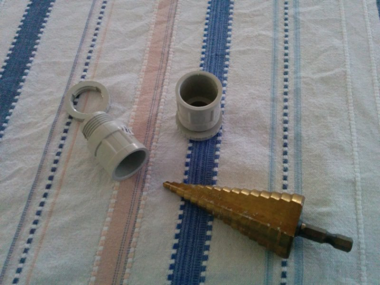
Then the transducer is fitted into the adaptor, even though it was a snug fit I still added some silicone sealant around it to seal out moisture and make sure it stays in place.
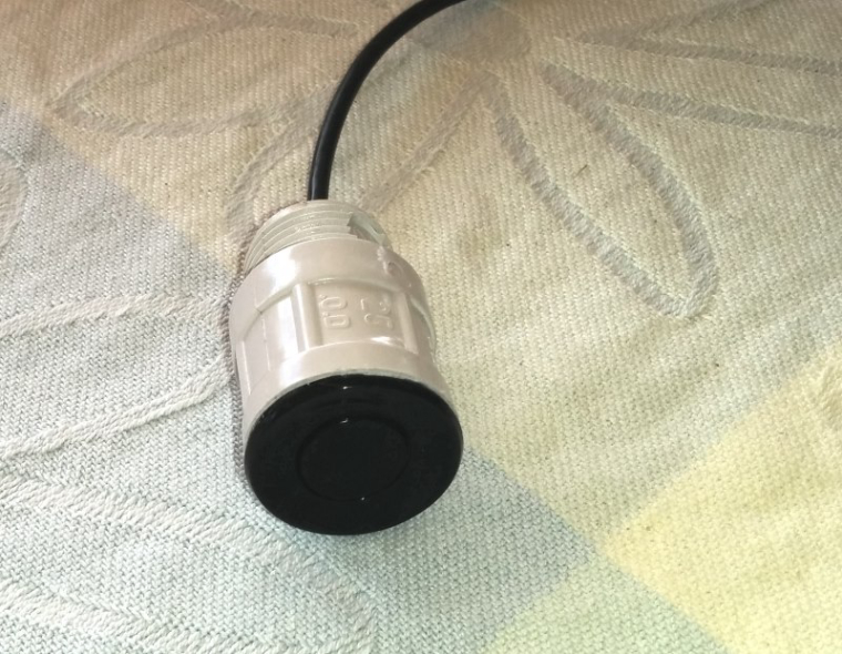
I then drilled a hole in the bottom of a 20mm round single entry junction box , mounted the adaptor and ran the wires through some conduit. The finished sensor looked like this.
The transducer needed to be around 30cm above the full water line to get a stable reading so I had to mount it towards the centre of the tank. I used a 25mm hole saw to cut a hole in the tank and the sensor unit just slips right on in. I was going to silicone it in place but it is a neat fit and is working well so will probably just leave it as it is.
-
@Boots33 These photos are fantastic!
It looks like you have the same stepped drill bit as me!! :)
This is really helpful. Now i can start tracking down the bits i need, although i already have a couple of those exact sensors, some flexi conduit, and 240v by the tanks for my pump, which is good (although I'm off grid so the 240v is really just a BIG battery with inverter!).
Im thinking of running two sensors (one for each tank side by side) off the same node - what would be the pros and cons of that do you think?
Thanks again for the great pics. It seems much more doable now and i know what i need.
@breimann said in Round water tank level sensor:
It looks like you have the same stepped drill bit as me!! :)
I just love those stepped drill bits. makes it so easy to drill large holes in boxes etc.
Im thinking of running two sensors (one for each tank side by side) off the same node - what would be the pros and cons of that do you think?
I think that would be a good idea as long as the transducer leads are long enough to reach your node from both tanks. If you are not using the node as a repeater like I am you could also sleep the node between readings as well perhaps. The newping library can handle multiple transducers without any problems.
-
@Boots33 These photos are fantastic!
It looks like you have the same stepped drill bit as me!! :)
This is really helpful. Now i can start tracking down the bits i need, although i already have a couple of those exact sensors, some flexi conduit, and 240v by the tanks for my pump, which is good (although I'm off grid so the 240v is really just a BIG battery with inverter!).
Im thinking of running two sensors (one for each tank side by side) off the same node - what would be the pros and cons of that do you think?
Thanks again for the great pics. It seems much more doable now and i know what i need.
@breimann said in Round water tank level sensor:
(although I'm off grid so the 240v is really just a BIG battery with inverter!).
Wow, are you in a remote area or just off grid by choice?
-
@breimann said in Round water tank level sensor:
(although I'm off grid so the 240v is really just a BIG battery with inverter!).
Wow, are you in a remote area or just off grid by choice?
@Boots33 Off grid by choice... in country South Australia.
Yeah, i thought of the lead issue, but the tanks are fairly close together (less than a metre apart) so i might be able to pull it off... anyway, i want to finish a few nodes off for inside our "shouse" (we live in a shed), and i'm still trying to complete my Pump Controller node so we'll see how we go slowly collecting the parts.
-
@Boots33 Off grid by choice... in country South Australia.
Yeah, i thought of the lead issue, but the tanks are fairly close together (less than a metre apart) so i might be able to pull it off... anyway, i want to finish a few nodes off for inside our "shouse" (we live in a shed), and i'm still trying to complete my Pump Controller node so we'll see how we go slowly collecting the parts.
I am in South East Qld so in the same country at least :)
I remember the controller, that is the one you were going to use a ACS712 I think.
I did build a controller for my tank pump but it is just a simple on off node.