Current Sensing?
-
too hard to resist, so first draft freshly printed
-
@scalz - I hate being a student and having no time. Beat me to it! Do you have the circuitry sorted?
What 3D modelling software do you use? Fusion, solidworks?
Also, what size have you made that, what size PCB would it accept?
-
@scalz
It may be a good idea to make an housing for the phototransistor that is basically an led, so you can have pcb externally in the same box with the Arduino.@gohan - While it would be possible, its not allowing much surface to attach to the meter. My soloution will be out by tonight i hope. I'm proposing we attach this module to the meter and connect into another board that is attached to the side of the meter that is the heart of the module (a atmega328 board). The designs and schematic anyway, we can then ponder over what my designs call and we can improve before production and release to openhardware.io
-
From my initial bit of research, the product that we were talking about from OpenEnergyMonitor doesn't seem to be optimized for detecting a blinking LED. It works, but is not optimized for best result. If the pulse started becoming relatively quick for any reason then this would start to saturate and the LDR will not return to its normal status quick enough. I'm designing using a compactor and photodiode to get around this issue. Schematics are nearly done and will attempt to get this PCB small as possible for either my own 3d printable model to stick onto the meter or @scalz.
Could you possibly share that model at all @scalz? Obviously, depending on what engine you have used to create this that is :)
-
I dont know it its worth anything, but here is my solution for a energymonitor (pulse counter)
https://www.byggahus.se/forum/attachment.php?attachmentid=156953&d=1445108667
https://www.byggahus.se/forum/attachment.php?attachmentid=156955&d=1445109103
https://www.byggahus.se/forum/attachment.php?attachmentid=208900&d=1486415706And to asnwer your question above, I use this for my hole house, and are going to build a portable current sensing monitor which i can move around and measure different outlets.
@sundberg84 - An interested little throw together!
I really like the idea of that portable current sensor to move around. Please do publish those designs, that is something that could be of use to some!
-
@gohan - While it would be possible, its not allowing much surface to attach to the meter. My soloution will be out by tonight i hope. I'm proposing we attach this module to the meter and connect into another board that is attached to the side of the meter that is the heart of the module (a atmega328 board). The designs and schematic anyway, we can then ponder over what my designs call and we can improve before production and release to openhardware.io
-
@Samuel235
Of course it would need a bigger surface than an led diameter, but could be smaller in volume.@gohan The trouble is though, as i mentioned just in the post regarding the product from OpenEnergyMonitor, a photo transistor is not the best/optimal way to go about this. As the LM393 module is built, it is the correct method. Using a photodiode and a comparator. No one seems to be doing that, and this is exactly what i'm doing right now. I'm pretty confident we can get this to a size that would satisfy your suggestions, we shall see.
Edit: Typo.
-
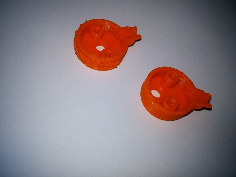
Beep beep lol
I'm joking. That was really quick to do. The box is same size 22mm. I'm not sure to see the point of making it smaller as it needs holding points.
I've used solidworks.
Yep I've done the pcb too. Ultra low power, a few parts. But I need to test the circuit (maybe at lunch) as I'm not planning to use comp nor amp. Again I did it because it was quick and because I can :) -
Beep beep lol
I'm joking. That was really quick to do. The box is same size 22mm. I'm not sure to see the point of making it smaller as it needs holding points.
I've used solidworks.
Yep I've done the pcb too. Ultra low power, a few parts. But I need to test the circuit (maybe at lunch) as I'm not planning to use comp nor amp. Again I did it because it was quick and because I can :)@scalz - I might as well just leave it to you >.<
Nice, solidworks is what i'm using at the moment too. Fancy sharing the files or is it just a quick rough idea that you're not sticking with?
Would be nice to compare the two designs together for the circuit. I might see about getting a board produced at my Uni on the routing machine. Lets both make our versions and would be nice to compare them side by side. (I'm thinking about sending you one of mine once its produced, and you're welcome to scrutinise it to help me improve)
Out of interest, i'm looking at either 3.5mm audio jack or RJ45 (RJ45 looks to be a slightly cheaper route) to connect back to the 'arduino' box. What are you thinking of doing for connectivity?
-
It took me less an hour for the box+pcb..i wouldn't have invest more time as i've lot of others stuff to do.
For the connector, I let the user choosing as I'm not really planning to design a dedicated pcb for the mcu side. Because there are already lot of boards and it just need one signal. Or I have multiple custom dev board with usb connection too etc. I was mainly interested in doing a low power sensor with a good digital level. Now I need to check my little idea.. -
It took me less an hour for the box+pcb..i wouldn't have invest more time as i've lot of others stuff to do.
For the connector, I let the user choosing as I'm not really planning to design a dedicated pcb for the mcu side. Because there are already lot of boards and it just need one signal. Or I have multiple custom dev board with usb connection too etc. I was mainly interested in doing a low power sensor with a good digital level. Now I need to check my little idea..@scalz - Perfect, okay. Well i will sort something out with the MCU side in mine then. I might go down the route of custom board, but then again, it may be easier for the user to just use a arduino maybe, just that the connection of the sensor would be a little 'temp' if i don't do a custom board maybe. Not sure yet. Will get the sensor product sorted first.
-
@gohan The trouble is though, as i mentioned just in the post regarding the product from OpenEnergyMonitor, a photo transistor is not the best/optimal way to go about this. As the LM393 module is built, it is the correct method. Using a photodiode and a comparator. No one seems to be doing that, and this is exactly what i'm doing right now. I'm pretty confident we can get this to a size that would satisfy your suggestions, we shall see.
Edit: Typo.
-
assembled my sensor this noon.
It looks like this from the top view, with the indication led (optional if battery powered device). The sensor is of course on bottom.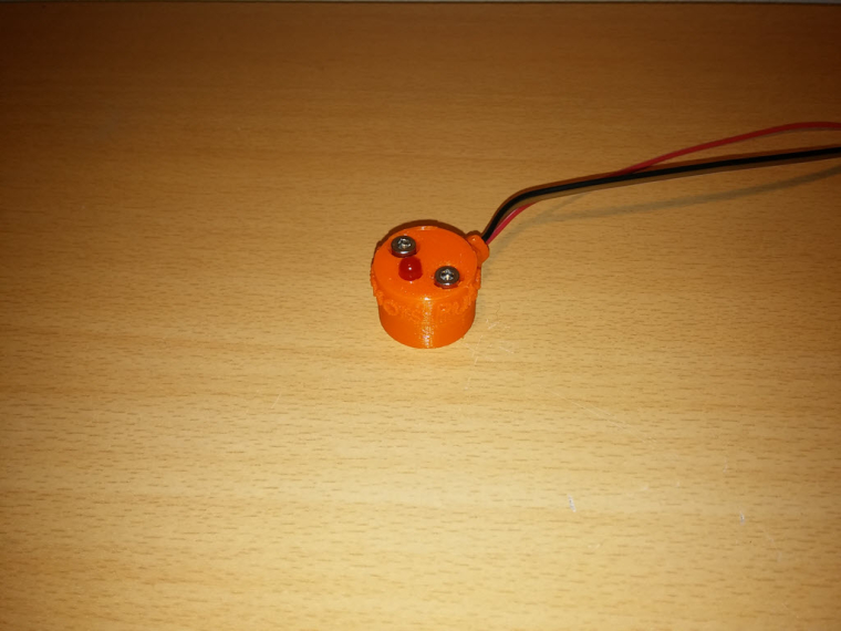
So i just ran a few tests and was able to detect up to 40hz. Then missed pulses started. but i've not tweaked it yet.
My test config was a signal generator connected to an external led, put it in front of my sensor. And checked the result with a scope.
I think 40Hz should be enough lol, and was very suprised i was able to go as high with my circuit, that's cool.I'll upload my files at openhardware
Enjoy MySensors Pulse :)
-
assembled my sensor this noon.
It looks like this from the top view, with the indication led (optional if battery powered device). The sensor is of course on bottom.So i just ran a few tests and was able to detect up to 40hz. Then missed pulses started. but i've not tweaked it yet.
My test config was a signal generator connected to an external led, put it in front of my sensor. And checked the result with a scope.
I think 40Hz should be enough lol, and was very suprised i was able to go as high with my circuit, that's cool.I'll upload my files at openhardware
Enjoy MySensors Pulse :)
-
@Samuel235
My bet is there isn't one :D -
@Samuel235
My bet is there isn't one :D -
@gohan - I'd be pretty shocked if there was when it was made this quick. Either way, its very nice and a quick turn around.
-
@Samuel235 do not underestimate the @scalz man!