MySensors weather station
-
This is the official (US)National Weather Service definition of wind gust. It looks like they dont report gusts until wind speed is above a certain amount. I like to overcomplicate things, so I would report the average, max in a minute (like Yveaux), and a standard deviation(just to be fancy)
https://graphical.weather.gov/definitions/defineWindGust.html
-
@tombstone thanks.
Trying to run some tests today. I think I have some workable code, but I don't have any sleep figured in yet. With all of the sensors being run from one pro mini, there is a lot going on and I will need to figure sleep in carefully if I even do. I have temp, humidity, rain, wind direction and wind speed. Arduino IDE says that it takes 75% of the program memory and that is not with debugging on. If I turn that on I start to get warnings, but it will compile and run.
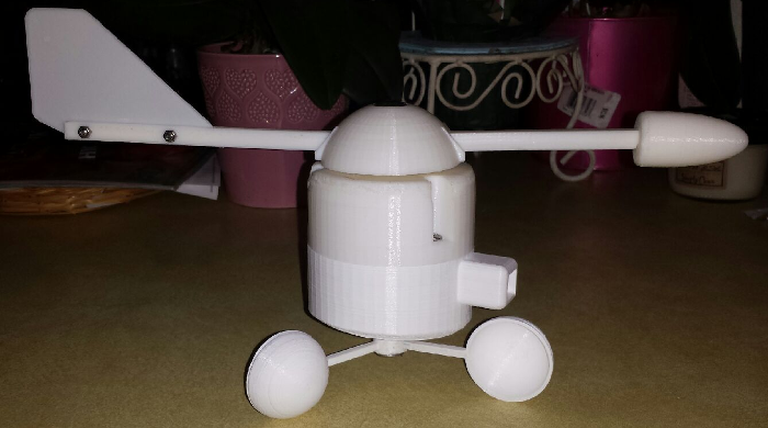
Getting even closer to being able to mount this on my roof.
-
So I am running into a problem with the code I am working on. Specifically the wind direction sensor. When I reset the node, the first loop of the main loop, it gets the wind direction fine, but gets an incorrect reading every time after regardless of where I position the sensor. Here is a snippet of the debug output:
Sensor Presentation Complete
New Sensor State... Sensor: Not Tripped

...................................
Anemometer speed in Hz 0.00
Current wind speed is 0
Current average wind speed is 0.00
...................................
Wind position: 231
Wind direction: 52
-----------------------------------
Temperature is: 74.84
===================================
Humidity is: 53.20

...................................
Anemometer speed in Hz 0.00
Current wind speed is 0
Current average wind speed is 0.00
===================================
Humidity is: 53.50

...................................
Anemometer speed in Hz 0.00
Current wind speed is 0
Current average wind speed is 0.00
...................................
Wind position: 179
Wind direction: 0

...................................
Anemometer speed in Hz 0.00
Current wind speed is 0
Current average wind speed is 0.00

...................................
Anemometer speed in Hz 0.00
Current wind speed is 0
Current average wind speed is 0.00

...................................
Anemometer speed in Hz 0.00
Current wind speed is 0
Current average wind speed is 0.00
...................................
Wind position: 179
Wind direction: 0

...................................
Anemometer speed in Hz 0.00
Current wind speed is 0
Current average wind speed is 0.00
As you can see, the initial reading shows the following:
Wind position: 231
Wind direction: 52
After that, every reading shows:
Wind position: 179
Wind direction: 0
All sensor readings are getting transmitted back to my Vera controller fine. Here is the full sketch for the node:
/*
 Arduino Tipping Bucket Rain Gauge

 April 26, 2015

 Version 2.0

 Arduino Tipping Bucket Rain Gauge

 Utilizing a tipping bucket sensor, your Vera home automation controller and the MySensors.org
 gateway you can measure and sense local rain.  This sketch will create two devices on your
 Vera controller.  One will display your total precipitation for the last 5 days.  The other,
 a sensor that changes state if there is recent rain (up to last 120 hours)  above a threshold.
 Both these settings are user definable.

 There is a build overview video here: https://youtu.be/1eMfKQaLROo

 This sketch features the following:

 * Allows you to set the rain threshold in mm
 * Allows you to determine the tripped indicator window up to 120 hours.
 * Displays the last 5 days of rain in Variable1 through Variable5
   of the Rain Sensor device
 * Configuration changes to Sensor device updated every hour
 * Should run on any Arduino
 * Will retain Tripped/Not Tripped status and data in a power interruption, saving small amount
   of data to EEPROM (Circular Buffer to maximize life of EEPROM)
 * LED status indicator
 * Optional Temp/Humidity (DHT-22 or DHT-11) and Light LUX (BH1750) sensors. To use, uncomment
   #define DHT_ON  and/or #define LUX_ON
 * Optionally send total accumulation of each day's rainfall or send only individual days rainfall totals.
   Uncomment #define USE_DAILY to display individual daily rainfall.  If it is commented out it will display
   a cumulative total rainfall (day4 = day1+day2+day3+day4 etc)

 by @BulldogLowell and @PeteWill for free public use

 */

//#define MY_DEBUG // Enable MySensors debug prints to serial monitor

// Enable and select radio type attached
#define MY_RADIO_NRF24
//#define MY_RADIO_RFM69

//#define MY_NODE_ID 7 //uncomment this line to assign a static ID

#include "AS5047.h"
#include <SPI.h>
#include <math.h>
#include <TimeLib.h>
#include <MySensors.h>

#define SKETCH_NAME "Weather Station"
#define SKETCH_VERSION "2.0"

#define DWELL_TIME 40  // this allows for radio to come back to power after a transmission, ideally 0

#define DEBUG_ON  // Rain gauge specific debug messages.
#define RAIN_ON // uncomment out this line to enable the rain sensor
#define DHT_ON // uncomment out this line to enable DHT sensor
//#define LUX_ON // uncomment out this line to enable BH1750 sensor
#define ANEMOMETER_ON // uncomment out this line to enable anemometer sensor
#define AS5047_ON // uncomment out this line to enable AS5047 wind direction sensor
#define USE_DAILY // Uncomment to display individual daily rainfall totals in the variables sent to your controller. If it's commented it will add each day to the next for a cumulative total.

#define NORTH_SWITCH_PIN 7 //The north calibration switch
#define AS5047_CHIP_SELECT_PIN 5 //The north calibration switch
#define ANEMOMETER_PIN 2 //The wind speed sensor

#define TIP_SENSOR_PIN 3 //The tipping bucket rain sensor
#define CALIBRATE_FACTOR 60 // amount of rain per rain bucket tip e.g. 5 is .05mm

#define DHT_LUX_DELAY 3000  //Delay in milliseconds that the DHT and LUX sensors will wait before sending data
#define WIND_DIR_DELAY 5000  //Delay in milliseconds that the wind direction sensor will wait before sending data
#define NORTH_OFFSET_BUTTON_DELAY 5000  //Delay in milliseconds that the DHT and LUX sensors will wait before sending data

#define CHILD_ID_RAIN_LOG 3  // Keeps track of accumulated rainfall
#define CHILD_ID_TRIPPED_INDICATOR 4  // Indicates Tripped when rain detected
#define CHILD_ID_WIND 5  // Indicates Tripped when rain detected

#define EEPROM_NORTH_OFFSET_LOCATION 0  // location of the EEPROM circular buffer
#define EEPROM_BUFFER_LOCATION 2  // location of the EEPROM circular buffer
#define E_BUFFER_LENGTH 240
#define RAIN_BUCKET_SIZE 120

#ifdef  DEBUG_ON
  #define DEBUG_PRINT(x)   Serial.print(x)
  #define DEBUG_PRINTLN(x) Serial.println(x)
  #define SERIAL_START(x)  Serial.begin(x)
  #else
  #define DEBUG_PRINT(x)
  #define DEBUG_PRINTLN(x)
  #define SERIAL_START(x)
#endif
//
MyMessage msgRainRate(CHILD_ID_RAIN_LOG, V_RAINRATE);
MyMessage msgRain(CHILD_ID_RAIN_LOG, V_RAIN);
//
MyMessage msgRainVAR1(CHILD_ID_RAIN_LOG, V_VAR1);
MyMessage msgRainVAR2(CHILD_ID_RAIN_LOG, V_VAR2);
MyMessage msgRainVAR3(CHILD_ID_RAIN_LOG, V_VAR3);
MyMessage msgRainVAR4(CHILD_ID_RAIN_LOG, V_VAR4);
MyMessage msgRainVAR5(CHILD_ID_RAIN_LOG, V_VAR5);
//
MyMessage msgTripped(CHILD_ID_TRIPPED_INDICATOR, V_TRIPPED);
MyMessage msgTrippedVar1(CHILD_ID_TRIPPED_INDICATOR, V_VAR1);
MyMessage msgTrippedVar2(CHILD_ID_TRIPPED_INDICATOR, V_VAR2);

#ifdef ANEMOMETER_ON
MyMessage msgWindSpeed(CHILD_ID_WIND, V_WIND);
MyMessage msgWindGust(CHILD_ID_WIND, V_GUST);
#endif
#ifdef AS5047_ON
MyMessage msgWindDirection(CHILD_ID_WIND, V_DIRECTION);
#endif
//
#ifdef DHT_ON
  #include <DHT.h>
  #define CHILD_ID_HUM 0
  #define CHILD_ID_TEMP 1
  #define HUMIDITY_SENSOR_DIGITAL_PIN 6
  DHT dht;
  float lastTemp;
  float lastHum;
  bool metric = false;
  MyMessage msgHum(CHILD_ID_HUM, V_HUM);
  MyMessage msgTemp(CHILD_ID_TEMP, V_TEMP);
#endif
//
#ifdef LUX_ON
  //BH1750 is connected to SCL (analog input A5) and SDA (analog input A4)
  #include <BH1750.h>
  #include <Wire.h>
  #define CHILD_ID_LIGHT 2
  BH1750 lightSensor;
  MyMessage msg(CHILD_ID_LIGHT, V_LIGHT_LEVEL);
  unsigned int lastlux;
  uint8_t heartbeat = 10; //Used to send the light lux to gateway as soon as the device is restarted and after the DHT_LUX_DELAY has happened 10 times
#endif

#ifdef ANEMOMETER_ON
volatile unsigned long startTime = 0; //stores start time for wind speed calculation
unsigned long dataTimer = 0; //used to track how often to communicate data
unsigned long gustTimer = 0; //used to track how often to communicate wind gust data
volatile float pulseTime = 0; //stores time between one anemomter relay closing and the next
volatile float cumulativePulseTime = 0; //stores cumulative pulsetimes for averaging
volatile bool start = true; //tracks when a new anemometer measurement starts
volatile unsigned int averageWindCount = 0; //stores anemometer relay counts for doing average wind speed
int16_t gustMax = 0; //stores the max reported wind speed used for the V_GUST value
float alarmSetting = 60.0; //wind speed setting to signal alarm
#endif

#ifdef AS5047_ON
AS5047 myAS5047(AS5047_CHIP_SELECT_PIN); //Wind direction magnetic position sensor
long north_offset;
bool button;
int wind_direction;
int last_direction;
long wind_position;
#endif

unsigned long sensorPreviousMillis;

#ifdef AS5047_ON
unsigned long windDirPreviousMillis;
unsigned long northButtonPreviousMillis;
#endif

int eepromIndex;
int tipSensorPin = 3; // Pin the tipping bucket is connected to. Must be interrupt capable pin
int ledPin = 8; // Pin the LED is connected to.  PWM capable pin required
#ifdef DEBUG_ON
unsigned long dataMillis;
unsigned long serialInterval = 600000UL;
#endif
const unsigned long oneHour = 3600000UL;
unsigned long lastTipTime;
unsigned long lastRainTime; //Used for rainRate calculation
unsigned int rainBucket [RAIN_BUCKET_SIZE] ; /* 24 hours x 5 Days = 120 hours */
unsigned int rainRate = 0;
uint8_t rainWindow = 72;         //default rain window in hours.  Will be overwritten with msgTrippedVar1.
volatile int wasTippedBuffer = 0;
int rainSensorThreshold = 50; //default rain sensor sensitivity in hundredths.  Will be overwritten with msgTrippedVar2.
uint8_t state = 0;
uint8_t oldState = 2; //Setting the default to something other than 1 or 0
unsigned int lastRainRate = 0;
int lastMeasure = 0;
bool gotTime = false;
uint8_t lastHour;
uint8_t currentHour;
//
void presentation()  {
  // Register all sensors to gw (they will be created as child devices)
  sendSketchInfo(SKETCH_NAME, SKETCH_VERSION);
  wait(DWELL_TIME);
  present(CHILD_ID_RAIN_LOG, S_RAIN);
  wait(DWELL_TIME);
  present(CHILD_ID_TRIPPED_INDICATOR, S_MOTION);
  wait(DWELL_TIME);
#ifdef ANEMOMETER_ON OR AS5047_ON
  present(CHILD_ID_WIND, S_WIND);
  wait(DWELL_TIME);
#endif

#ifdef DHT_ON
  present(CHILD_ID_HUM, S_HUM);
  wait(DWELL_TIME);
  present(CHILD_ID_TEMP, S_TEMP);
  wait(DWELL_TIME);
#endif


#ifdef LUX_ON
  present(CHILD_ID_LIGHT, S_LIGHT_LEVEL);
#endif

  DEBUG_PRINTLN(F("Sensor Presentation Complete"));
}

void setup()
{
  #ifndef MY_DEBUG
  SERIAL_START(115200);  //Start serial if MySensors debugging isn't enabled
  #endif
  //
  pinMode(NORTH_SWITCH_PIN, INPUT_PULLUP);

#ifdef ANEMOMETER_ON
  pinMode(ANEMOMETER_PIN, INPUT_PULLUP); //set interrupt pin to input pullup
  attachInterrupt(ANEMOMETER_PIN, anemometerISR, RISING); //setup interrupt on anemometer input pin, interrupt will occur whenever falling edge is detected
  dataTimer = millis(); //reset loop timer
  gustTimer = millis(); //reset loop timer
#endif

  // Set up the IO
  pinMode(TIP_SENSOR_PIN, INPUT_PULLUP);
  attachInterrupt (digitalPinToInterrupt(TIP_SENSOR_PIN), bucketSensorTippedISR, FALLING);  // depending on location of the hall effect sensor may need CHANGE
  pinMode(ledPin, OUTPUT);
  digitalWrite(ledPin, HIGH);
  //
  //Sync time with the server
  //
  unsigned long functionTimeout = millis();
  while (timeStatus() == timeNotSet && millis() - functionTimeout < 30000UL)
  {
    requestTime();
    DEBUG_PRINTLN(F("Getting Time"));
    wait(1000); // call once per second
    DEBUG_PRINTLN(F("."));
  }
  currentHour = hour();
  lastHour = hour();
  //
  //retrieve from EEPROM stored values on a power cycle.
  //

#ifdef AS5047_ON
  //Get the north offset direction
  getNorthOffset();
#endif

  bool isDataOnEeprom = false;
  for (int i = 0; i < E_BUFFER_LENGTH; i++)
  {
    uint8_t locator = loadState(EEPROM_BUFFER_LOCATION + i);
    if (locator == 0xFE)  // found the EEPROM circular buffer index
    {
      eepromIndex = EEPROM_BUFFER_LOCATION + i;
      DEBUG_PRINT(F("EEPROM Index "));
      DEBUG_PRINTLN(eepromIndex);
      //Now that we have the buffer index let's populate the rainBucket[] with data from eeprom
      loadRainArray(eepromIndex);
      isDataOnEeprom = true;
      break;
    }
  }
  //
  if (!isDataOnEeprom) // Added for the first time it is run on a new Arduino
  {
    DEBUG_PRINTLN(F("I didn't find valid EEPROM Index, so I'm writing one to location 0"));
    eepromIndex = EEPROM_BUFFER_LOCATION;
    saveState(eepromIndex, 0xFE);
    saveState(eepromIndex + 1, 0xFE);
    //then I will clear out any bad data
    for (int i = 2; i <= E_BUFFER_LENGTH; i++)
    {
      saveState(i, 0x00);
    }
  }
  #ifdef DEBUG_ON
  dataMillis = millis();
  #endif
  lastTipTime = millis();
  //
  request(CHILD_ID_TRIPPED_INDICATOR, V_VAR1);
  wait(DWELL_TIME);
  request(CHILD_ID_TRIPPED_INDICATOR, V_VAR2);
  wait(DWELL_TIME);
  //
#ifdef DHT_ON
  dht.setup(HUMIDITY_SENSOR_DIGITAL_PIN);
  metric = getConfig().isMetric;
  //metric = false;
  wait(DWELL_TIME);
#endif
  //
#ifdef LUX_ON
  lightSensor.begin();
#endif
  //
  transmitRainData(); //Setup complete send any data loaded from eeprom to gateway
}

void loop()
{
  if (state)
  {
    prettyFade();  // breathe if tripped
  }
  else
  {
    slowFlash();   // blink if not tripped
  }
#ifdef DEBUG_ON  // Serial Debug Block
  if ( (millis() - dataMillis) >= serialInterval)
  {
    for (int i = 24; i <= 120; i = i + 24)
    {
      updateSerialData(i);
    }
    dataMillis = millis();
  }
#endif

#ifdef RAIN_ON
  //
  // let's constantly check to see if the rain in the past rainWindow hours is greater than rainSensorThreshold
  //
  int measure = 0; // Check to see if we need to show sensor tripped in this block
  for (int i = 0; i < rainWindow; i++)
  {
    measure += rainBucket [i];
    if (measure != lastMeasure)
    {
      //      DEBUG_PRINT(F("measure value (total rainBucket within rainWindow): "));
      //      DEBUG_PRINTLN(measure);
      lastMeasure = measure;
    }
  }
  //
  state = (measure >= (rainSensorThreshold * 100));
  if (state != oldState)
  {
    send(msgTripped.set(state));
    wait(DWELL_TIME);
    DEBUG_PRINT(F("New Sensor State... Sensor: "));
    DEBUG_PRINTLN(state ? "Tripped" : "Not Tripped");
    oldState = state;
  }
#endif

#ifdef ANEMOMETER_ON
  // The radius from center to the reed switch is 27.5mm or 1.082677 inches.  This gives us a circumference of
  // 6.80266 inches traveled for every tick of the reed switch.  This converts to 0.5668883 feet per revolution.
  // That makes 9,314 revolutions per mile.  This calculates to 1 Hz = 2.5872 MPh

  if((millis() - startTime) > 2500) pulseTime = 0; //if the wind speed has dropped below 1MPH than set it to zero

   //See if it is time to transmit
  if((millis() - dataTimer) > 1800)
  {

    detachInterrupt(ANEMOMETER_PIN); //shut off wind speed measurement interrupt until done communication
    float aWSpeed = getAvgWindSpeed(cumulativePulseTime,averageWindCount); //calculate average wind speed

    cumulativePulseTime = 0; //reset cumulative pulse counter
    averageWindCount = 0; //reset average wind count

    float aFreq = 0; //set to zero initially
    if(pulseTime > 0.0) aFreq = getAnemometerFreq(pulseTime); //calculate frequency in Hz of anemometer, only if pulsetime is non-zero
    int16_t wSpeedMPH = getWindMPH(aFreq); //calculate wind speed in MPH, note that the 2.5 comes from anemometer data sheet
    if(wSpeedMPH > gustMax) gustMax = wSpeedMPH; //Update our highest wind speed for our V_GUST value

    DEBUG_PRINTLN();
    DEBUG_PRINTLN("...................................");
    DEBUG_PRINT("Anemometer speed in Hz ");
    DEBUG_PRINTLN(aFreq);
    DEBUG_PRINT("Current wind speed is ");
    DEBUG_PRINTLN(wSpeedMPH);
    DEBUG_PRINT("Current average wind speed is ");
    DEBUG_PRINTLN(aWSpeed);

    send(msgWindSpeed.set(wSpeedMPH));
    wait(DWELL_TIME);

    start = true; //reset start variable in case we missed wind data while communicating current data out
    attachInterrupt(digitalPinToInterrupt(ANEMOMETER_PIN), anemometerISR, RISING); //turn interrupt back on
    dataTimer = millis(); //reset loop timer
  }

  //Send the wind gust speed every minute
  if((millis() - gustTimer) > 60000)
  {
    send(msgWindGust.set(gustMax));
    wait(DWELL_TIME);

    DEBUG_PRINTLN("...................................");
    DEBUG_PRINT("Current wind gust speed is ");
    DEBUG_PRINTLN(gustMax);

    gustMax = 0; //Reset for the next wind gust speed
    gustTimer = millis(); //reset loop timer
  }
#endif

#ifdef AS5047_ON
  //
  button = digitalRead(NORTH_SWITCH_PIN);
  if (!button && (millis() - northButtonPreviousMillis > NORTH_OFFSET_BUTTON_DELAY)) {
    setNorthOffset();
    northButtonPreviousMillis = millis();
  }

  //
  getNorthOffset();
  wind_position = myAS5047.sensor_read();
  long value = (359*wind_position)/16383;
  wind_direction = ((value - north_offset) < 0) ? 360 - abs(value - north_offset) : value - north_offset;

  if (millis() - windDirPreviousMillis > WIND_DIR_DELAY)
  {
    DEBUG_PRINTLN("...................................");
    DEBUG_PRINT("Wind position: ");
    DEBUG_PRINTLN(value);
    DEBUG_PRINT("Wind direction: ");
    DEBUG_PRINTLN(wind_direction);

    if (wind_direction != last_direction)
    {
      send(msgWindDirection.set((int) wind_direction));
      wait(DWELL_TIME);
    }
    last_direction = wind_direction;
    windDirPreviousMillis = millis();
  }
#endif

#ifdef RAIN_ON
  //
  unsigned long tipDelay = millis() - lastRainTime;
  if (wasTippedBuffer) // if was tipped, then update the 24hour total and transmit to Vera
  {
    DEBUG_PRINTLN(F("Sensor Tipped"));
    DEBUG_PRINT(F("rainBucket [0] value: "));
    DEBUG_PRINTLN(rainBucket [0]);
    send(msgRain.set((float)rainTotal(currentHour) / 100, 1)); //Calculate the total rain for the day
    wait(DWELL_TIME);
    wasTippedBuffer--;
    rainRate = ((oneHour) / tipDelay);
    if (rainRate != lastRainRate)
    {
      send(msgRainRate.set(rainRate, 1));
      wait(DWELL_TIME);
      DEBUG_PRINT(F("RainRate= "));
      DEBUG_PRINTLN(rainRate);
      lastRainRate = rainRate;
    }
    lastRainTime = lastTipTime;
  }
  //
  currentHour = hour();
  if (currentHour != lastHour)
  {
    DEBUG_PRINTLN(F("One hour elapsed."));
    send(msgRain.set((float)rainTotal(currentHour) / 100, 1)); // send today's rainfall
    wait(DWELL_TIME);
    saveState(eepromIndex, highByte(rainBucket[0]));
    saveState(eepromIndex + 1, lowByte(rainBucket[0]));
    DEBUG_PRINT(F("Saving rainBucket[0] to eeprom. rainBucket[0] = "));
    DEBUG_PRINTLN(rainBucket[0]);
    for (int i = RAIN_BUCKET_SIZE - 1; i >= 0; i--)//cascade an hour of values back into the array
    {
      rainBucket [i + 1] = rainBucket [i];
    }
    request(CHILD_ID_TRIPPED_INDICATOR, V_VAR1);
    wait(DWELL_TIME);
    request(CHILD_ID_TRIPPED_INDICATOR, V_VAR2);
    wait(DWELL_TIME);
    rainBucket[0] = 0;
    eepromIndex = eepromIndex + 2;
    if (eepromIndex > EEPROM_BUFFER_LOCATION + E_BUFFER_LENGTH)
    {
      eepromIndex = EEPROM_BUFFER_LOCATION;
    }
    DEBUG_PRINT(F("Writing to EEPROM.  Index: "));
    DEBUG_PRINTLN(eepromIndex);
    saveState(eepromIndex, 0xFE);
    saveState(eepromIndex + 1, 0xFE);
    requestTime(); // sync the time every hour
    wait(DWELL_TIME);
    transmitRainData();
    rainRate = 0;
    send(msgRainRate.set(rainRate, 1));
    wait(DWELL_TIME);
    DEBUG_PRINTLN(F("Sending rainRate is 0 to controller"));
    lastHour = hour();
  }
#endif
  if (millis() - sensorPreviousMillis > DHT_LUX_DELAY)
  {
    #ifdef DHT_ON  //DHT Code
      doDHT();
    #endif
    #ifdef LUX_ON
      doLUX();
    #endif
    sensorPreviousMillis = millis();
  }
}

#ifdef AS5047_ON
void getNorthOffset()
{
  north_offset =  (loadState(EEPROM_NORTH_OFFSET_LOCATION+1) << 8) | loadState(EEPROM_NORTH_OFFSET_LOCATION);
}

//
void setNorthOffset()
{
  DEBUG_PRINT("Direction value: ");
  DEBUG_PRINTLN(wind_direction);
  DEBUG_PRINT("North offset: ");
  DEBUG_PRINTLN(north_offset);
  if (north_offset != wind_direction)
  {
    saveState(EEPROM_NORTH_OFFSET_LOCATION, lowByte(wind_direction));
    saveState(EEPROM_NORTH_OFFSET_LOCATION+1, highByte(wind_direction));
    north_offset = wind_direction;
    DEBUG_PRINT("North offset set to: ");
    DEBUG_PRINTLN(wind_direction);
  }
}
#endif
//
#ifdef ANEMOMETER_ON
//using time between anemometer pulses calculate frequency of anemometer
float getAnemometerFreq(float pTime)
{
  return (1/pTime);
}
//Use anemometer frequency to calculate wind speed in MPH, note 2.5 comes from anemometer data sheet
float getWindMPH(float freq)
{
  return (freq*2.5872);
}
//uses wind MPH value to calculate KPH
int16_t getWindKPH(float wMPH)
{
  return (wMPH*1.61);
}
//Calculates average wind speed over given time period
float getAvgWindSpeed(float cPulse,int period)
{
  if(period) return getWindMPH(getAnemometerFreq((float)(cPulse/period)));
  else return 0; //average wind speed is zero and we can't divide by zero
}

//This is the interrupt service routine (ISR) for the anemometer input pin
//it is called whenever a falling edge is detected
void anemometerISR()
{
  unsigned long currentTime = millis(); //get current time
  if(!start) { //This is not the first pulse and we are not at 0 MPH so calculate time between pulses
   // test = currentTime - startTime;
    pulseTime = (float)(currentTime - startTime)/1000;
    cumulativePulseTime += pulseTime; //add up pulse time measurements for averaging
    averageWindCount++; //anemomter went around so record for calculating average wind speed
  }
  startTime = currentTime; //store current time for next pulse time calculation
  start = false; //we have our starting point for a wind speed measurement
}
#endif
//
#ifdef DHT_ON
void doDHT(void)
{
  float temperature = dht.getTemperature();
    if (isnan(temperature))
    {
      DEBUG_PRINTLN("-----------------------------------");
      DEBUG_PRINTLN(F("Failed reading temperature from DHT"));
    } else if (temperature != lastTemp)
    {
      lastTemp = temperature;
      if (!metric)
      {
        temperature = dht.toFahrenheit(temperature);
      }
      send(msgTemp.set(temperature, 1));
      wait(DWELL_TIME);
      DEBUG_PRINTLN("-----------------------------------");
      DEBUG_PRINT(F("Temperature is: "));
      DEBUG_PRINTLN(temperature);
    }
    float humidity = dht.getHumidity();;
    if (isnan(humidity))
    {
      DEBUG_PRINTLN("===================================");
      DEBUG_PRINTLN(F("Failed reading humidity from DHT"));
    } else if (humidity != lastHum)
    {
      lastHum = humidity;
      send(msgHum.set(humidity, 1));
      wait(DWELL_TIME);
      DEBUG_PRINTLN("===================================");
      DEBUG_PRINT(F("Humidity is: "));
      DEBUG_PRINTLN(humidity);
    }
}
#endif
//
#ifdef LUX_ON
void doLUX(void)
{
  unsigned int lux = lightSensor.readLightLevel();// Get Lux value
  DEBUG_PRINT(F("Current LUX Level: "));
  DEBUG_PRINTLN(lux);
  heartbeat++;
  if (lux != lastlux || heartbeat > 10)
  {
    send(msg.set(lux));
    lastlux = lux;
  }
  if (heartbeat > 10)
  {
    heartbeat = 0;
  }
}
#endif
//
void bucketSensorTippedISR()
{
  unsigned long thisTipTime = millis();
  if (thisTipTime - lastTipTime > 100UL)
  {
    rainBucket[0] += CALIBRATE_FACTOR; // adds CALIBRATE_FACTOR hundredths of unit each tip
    wasTippedBuffer++;
  }
  lastTipTime = thisTipTime;
}
//
int rainTotal(int hours)
{
  int total = 0;
  for ( int i = 0; i <= hours; i++)
  {
    total += rainBucket [i];
  }
  return total;
}

#ifdef DEBUG_ON
void updateSerialData(int x)
{
  DEBUG_PRINT(F("Rain last "));
  DEBUG_PRINT(x);
  DEBUG_PRINTLN(F(" hours: "));
  float tipCount = 0;
  for (int i = 0; i < x; i++)
  {
    tipCount = tipCount + rainBucket [i];
  }
  tipCount = tipCount / 100;
  DEBUG_PRINTLN(tipCount);
}
#endif

void loadRainArray(int eValue) // retrieve stored rain array from EEPROM on powerup
{
  for (int i = 1; i < RAIN_BUCKET_SIZE; i++)
  {
    eValue = eValue - 2;
    if (eValue < EEPROM_BUFFER_LOCATION)
    {
      eValue = EEPROM_BUFFER_LOCATION + E_BUFFER_LENGTH;
    }
    DEBUG_PRINT(F("EEPROM location: "));
    DEBUG_PRINTLN(eValue);
    uint8_t rainValueHigh = loadState(eValue);
    uint8_t rainValueLow = loadState(eValue + 1);
    unsigned int rainValue = rainValueHigh << 8;
    rainValue |= rainValueLow;
    rainBucket[i] = rainValue;
    //
    DEBUG_PRINT(F("rainBucket[ value: "));
    DEBUG_PRINT(i);
    DEBUG_PRINT(F("] value: "));
    DEBUG_PRINTLN(rainBucket[i]);
  }
}

void transmitRainData(void)
{
  DEBUG_PRINT(F("In transmitRainData. currentHour = "));
  DEBUG_PRINTLN(currentHour);
  int rainUpdateTotal = 0;
  for (int i = currentHour; i >= 0; i--)
  {
    rainUpdateTotal += rainBucket[i];
    DEBUG_PRINT(F("Adding rainBucket["));
    DEBUG_PRINT(i);
    DEBUG_PRINTLN(F("] to rainUpdateTotal."));
  }
  DEBUG_PRINT(F("TX Day 1: rainUpdateTotal = "));
  DEBUG_PRINTLN((float)rainUpdateTotal / 100.0);
  send(msgRainVAR1.set((float)rainUpdateTotal / 100.0, 1)); //Send current day rain totals (resets at midnight)
  wait(DWELL_TIME);
#ifdef USE_DAILY
  rainUpdateTotal = 0;
#endif
  for (int i = currentHour + 24; i > currentHour; i--)
  {
    rainUpdateTotal += rainBucket[i];
    DEBUG_PRINT(F("Adding rainBucket["));
    DEBUG_PRINT(i);
    DEBUG_PRINTLN(F("] to rainUpdateTotal."));
  }
  DEBUG_PRINT(F("TX Day 2: rainUpdateTotal = "));
  DEBUG_PRINTLN((float)rainUpdateTotal / 100.0);
  send(msgRainVAR2.set((float)rainUpdateTotal / 100.0, 1));
  wait(DWELL_TIME);
#ifdef USE_DAILY
  rainUpdateTotal = 0;
#endif
  for (int i = currentHour + 48; i > currentHour + 24; i--)
  {
    rainUpdateTotal += rainBucket[i];
    DEBUG_PRINT(F("Adding rainBucket["));
    DEBUG_PRINT(i);
    DEBUG_PRINTLN(F("] to rainUpdateTotal."));
  }
  DEBUG_PRINT(F("TX Day 3: rainUpdateTotal = "));
  DEBUG_PRINTLN((float)rainUpdateTotal / 100.0);
  send(msgRainVAR3.set((float)rainUpdateTotal / 100.0, 1));
  wait(DWELL_TIME);
#ifdef USE_DAILY
  rainUpdateTotal = 0;
#endif
  for (int i = currentHour + 72; i > currentHour + 48; i--)
  {
    rainUpdateTotal += rainBucket[i];
    DEBUG_PRINT(F("Adding rainBucket["));
    DEBUG_PRINT(i);
    DEBUG_PRINTLN(F("] to rainUpdateTotal."));
  }
  DEBUG_PRINT(F("TX Day 4: rainUpdateTotal = "));
  DEBUG_PRINTLN((float)rainUpdateTotal / 100.0);
  send(msgRainVAR4.set((float)rainUpdateTotal / 100.0, 1));
  wait(DWELL_TIME);
#ifdef USE_DAILY
  rainUpdateTotal = 0;
#endif
  for (int i = currentHour + 96; i > currentHour + 72; i--)
  {
    rainUpdateTotal += rainBucket[i];
    DEBUG_PRINT(F("Adding rainBucket["));
    DEBUG_PRINT(i);
    DEBUG_PRINTLN(F("] to rainUpdateTotal."));
  }
  DEBUG_PRINT(F("TX Day 5: rainUpdateTotal = "));
  DEBUG_PRINTLN((float)rainUpdateTotal / 100.0);
  send(msgRainVAR5.set((float)rainUpdateTotal / 100.0, 1));
  wait(DWELL_TIME);
}

void receive(const MyMessage &message)
{
  if (message.sensor == CHILD_ID_RAIN_LOG)
  {
    // nothing to do here
  }
  else if (message.sensor == CHILD_ID_TRIPPED_INDICATOR)
  {
    if (message.type == V_VAR1)
    {
      rainWindow = atoi(message.data);
      if (rainWindow > 120)
      {
        rainWindow = 120;
      }
      else if (rainWindow < 1)
      {
        rainWindow = 1;
      }
      if (rainWindow != atoi(message.data))   // if I changed the value back inside the boundries, push that number back to Vera
      {
        send(msgTrippedVar1.set(rainWindow));
      }
    }
    else if (message.type == V_VAR2)
    {
      rainSensorThreshold = atoi(message.data);
      if (rainSensorThreshold > 10000)
      {
        rainSensorThreshold = 10000;
      }
      else if (rainSensorThreshold < 1)
      {
        rainSensorThreshold = 1;
      }
      if (rainSensorThreshold != atoi(message.data))  // if I changed the value back inside the boundries, push that number back to Vera
      {
        send(msgTrippedVar2.set(rainSensorThreshold));
      }
    }
  }
}

void prettyFade(void)
{
  float val = (exp(sin(millis() / 2000.0 * PI)) - 0.36787944) * 108.0;
  analogWrite(ledPin, val);
}

void slowFlash(void)
{
  static bool ledState = true;
  static unsigned long pulseStart = millis();
  if (millis() - pulseStart < 100UL)
  {
    digitalWrite(ledPin, !ledState);
    pulseStart = millis();
  }
}

void receiveTime(unsigned long newTime)
{
  DEBUG_PRINTLN(F("Time received..."));
  setTime(newTime);
  char theTime[6];
  sprintf(theTime, "%d:%2d", hour(), minute());
  DEBUG_PRINTLN(theTime);
}
I have tried disabling different pieces of the code to see if something from one of the other sensors was causing it, but I cannot seem to find why this is happening.
Just to note, if I run this test sketch, it works fine for the direction sensor:
#include "AS5047.h"
#include <SPI.h>
#include <EEPROM.h>

#define SWITCH_PIN 7 //The north calibration switch

AS5047 myAS5047(5); // SS pin

int address = 0;      //EEPROM address counter
int north_offset = 0;
long value;
int dir;
bool button;

void setup()
{
  Serial.begin(115200);

  pinMode(SWITCH_PIN, INPUT_PULLUP);

  north_offset = EEPROM.read(address);
}

void loop()
{
  value=(360*myAS5047.sensor_read())/16383;
  dir = ((value - north_offset) < 0) ? 360 - abs(value - north_offset) : value - north_offset;

  Serial.print("measured direction: ");
  Serial.println(dir);
  Serial.print("north_offset: ");
  Serial.println(north_offset);

  button = digitalRead(SWITCH_PIN);
  north_offset = EEPROM.read(address);
  if (!button && north_offset != value) {
    EEPROM.write(address, value);
    north_offset = value;
    Serial.println("Button pressed");
  }

  delay(1000);
}
I am hoping that someone notices something that I am not seeing.
Thanks in advance.
-
I think I at least partially figured out the problem. As mentioned earlier, I may need to use transactions for this. Being that I have never used SPI, much less SPI transactions before, I have limited knowledge of how this works. My little understanding of what I have read about transactions, you call :
SPI.beginTransaction( [SPI SETTINGS HERE] );
   {device SPI code} ...
SPI.endTransaction();
If I understand this, you can use SPI settings specific to a device with [SPI SETTINGS HERE] while leaving things alone for other devices, correct?
So I started looking at the library for the AS5047P sensor and I see this line in the constructor:
SPCR = (1<<SPE) | (1<<MSTR) | (1<<CPHA) | (1<<SPR1) | (1<<SPR0); // slow down clock speed, set up spiI am assuming that this defines the settings that I would need for the beginTransaction(). If so, how do I decipher this into the settings I need to include in the beginTransaction() call?
What I did as a test is to move the above SPCR... line into the read_register function of the library like this:
uint32_t AS5047::read_register(uint32_t thisRegister)
{
        SPCR = (1<<SPE) | (1<<MSTR) | (1<<CPHA) | (1<<SPR1) | (1<<SPR0); // slow down clock speed, set up spi

        byte inByte = 0;   // incoming byte from the SPI
        long result = 0;   // result to return
        byte lowbyte = thisRegister & 0b0000000011111111;
        byte highbyte = (thisRegister >> 8);
        digitalWrite(_ss, LOW);
        SPI.transfer(highbyte); // first byte in
        result = SPI.transfer(lowbyte); // first byte out
        digitalWrite(_ss, HIGH);
        delayMicroseconds(10);
        digitalWrite(_ss, LOW);
        int bytesToRead = 2;
        while (bytesToRead-- > 0) {
                // shift the first byte left, then get the second byte:
                result = result << 8;
                inByte = SPI.transfer(0x00);
                // combine the byte with the previous one:
                result = result | inByte;
        }
        // take the chip select high to de-select:
        digitalWrite(_ss, HIGH);

        result = result & 0b0011111111111111;
        return(result);
}
Now I appear to be getting correct wind direction data, but I feel that this is not the correct approach to doing it.
Can anyone help?
Vera Plus running UI7 with MySensors, Sonoffs and 1-Wire devices
Visit my website for more Bits, Bytes and Ramblings from me: http://dan.bemowski.info/ -
I think I at least partially figured out the problem. As mentioned earlier, I may need to use transactions for this. Being that I have never used SPI, much less SPI transactions before, I have limited knowledge of how this works. My little understanding of what I have read about transactions, you call :
SPI.beginTransaction( [SPI SETTINGS HERE] );
   {device SPI code} ...
SPI.endTransaction();
If I understand this, you can use SPI settings specific to a device with [SPI SETTINGS HERE] while leaving things alone for other devices, correct?
So I started looking at the library for the AS5047P sensor and I see this line in the constructor:
SPCR = (1<<SPE) | (1<<MSTR) | (1<<CPHA) | (1<<SPR1) | (1<<SPR0); // slow down clock speed, set up spiI am assuming that this defines the settings that I would need for the beginTransaction(). If so, how do I decipher this into the settings I need to include in the beginTransaction() call?
What I did as a test is to move the above SPCR... line into the read_register function of the library like this:
uint32_t AS5047::read_register(uint32_t thisRegister)
{
        SPCR = (1<<SPE) | (1<<MSTR) | (1<<CPHA) | (1<<SPR1) | (1<<SPR0); // slow down clock speed, set up spi

        byte inByte = 0;   // incoming byte from the SPI
        long result = 0;   // result to return
        byte lowbyte = thisRegister & 0b0000000011111111;
        byte highbyte = (thisRegister >> 8);
        digitalWrite(_ss, LOW);
        SPI.transfer(highbyte); // first byte in
        result = SPI.transfer(lowbyte); // first byte out
        digitalWrite(_ss, HIGH);
        delayMicroseconds(10);
        digitalWrite(_ss, LOW);
        int bytesToRead = 2;
        while (bytesToRead-- > 0) {
                // shift the first byte left, then get the second byte:
                result = result << 8;
                inByte = SPI.transfer(0x00);
                // combine the byte with the previous one:
                result = result | inByte;
        }
        // take the chip select high to de-select:
        digitalWrite(_ss, HIGH);

        result = result & 0b0011111111111111;
        return(result);
}
Now I appear to be getting correct wind direction data, but I feel that this is not the correct approach to doing it.
Can anyone help?
@dbemowsk you're right about the need for spi transactions on this one.
The sensor's spi interface gets initialized in the constructor and is overwritten by the radio. I understand your 'fix' will work, as you reinitialize the SPI bus everytime, as the transactions do in a portable way.
I have no time atm but I'll try to figure out the transaction settings when possible.http://yveaux.blogspot.nl
-
@dbemowsk you're right about the need for spi transactions on this one.
The sensor's spi interface gets initialized in the constructor and is overwritten by the radio. I understand your 'fix' will work, as you reinitialize the SPI bus everytime, as the transactions do in a portable way.
I have no time atm but I'll try to figure out the transaction settings when possible.@Yveaux Thanks. I have been trying to research it in the mean time, buy as of yet have not figured out how to do it. If you know of any websites that explain how to do it, it would help.I try to figure things out on my own because then I understand them better.
Thanks for all of the help you have given me on this.
Vera Plus running UI7 with MySensors, Sonoffs and 1-Wire devices
Visit my website for more Bits, Bytes and Ramblings from me: http://dan.bemowski.info/ -
@Yveaux Thanks. I have been trying to research it in the mean time, buy as of yet have not figured out how to do it. If you know of any websites that explain how to do it, it would help.I try to figure things out on my own because then I understand them better.
Thanks for all of the help you have given me on this.
@dbemowsk Let's break that line down, using the ATmega328P datasheet (pg. 221,222):
SPCR = (1<<SPE) | (1<<MSTR) | (1<<CPHA) | (1<<SPR1) | (1<<SPR0)- SPCR : SPI Control Register 0
- Bits not explicitly stated are 0, and can be read as (0<<xxx)
- (1<<SPE) : Enable SPI
- (0<<DORD) : Data order; here 0 to indicate MSB first
- (1<<MSTR) : Master/slave select; here 1 to indicate master
- (0<<CPOL): Clock polarity; here 0 to indicate SCK is low when idle
- (1<<CPHA) : Clock phase; here 1 to indicate sample on trailing edge
- (1<<SPR1) | (1<<SPR0) : Clock rate select; here 011 indicating Fosc/128
The SPISettings is used as follows:
SPISettings(clockrate, order, mode)- Let's start with the easy one: clockrate.
The driver above uses Fosc/128, which is 16000000/128=125000 for a 16MHz crystal. This seems a safe value as the AS5047 datasheet states tclk=100ns, so it can handle 10MHz. - Order is just the DORD parameter, so MSBFIRST.
- Then the tricky one: SPI_MODE
Here's an extensive explanation. It's a combination of clock phase and clock polarity. Luckily the datasheet states explicitly: "The AS5047D SPI uses mode=1 (CPOL=0, CPHA=1) to exchange data.", so use SPI_MODE1
Putting things together and wrapping SPI communication with transactions the result should be be:
uint32_t AS5047::read_register(uint32_t thisRegister)
{
    ....
    SPI.beginTransaction( SPISettings(125000, MSBFIRST, SPI_MODE1) );
    ....
    digitalWrite(_ss, LOW);
    SPI.transfer(highbyte); // first byte in
    ....
    digitalWrite(_ss, HIGH);
    SPI.endTransaction()
    ....
}
The clockrate can be increased if you like.
http://yveaux.blogspot.nl
-
@dbemowsk Let's break that line down, using the ATmega328P datasheet (pg. 221,222):
SPCR = (1<<SPE) | (1<<MSTR) | (1<<CPHA) | (1<<SPR1) | (1<<SPR0)- SPCR : SPI Control Register 0
- Bits not explicitly stated are 0, and can be read as (0<<xxx)
- (1<<SPE) : Enable SPI
- (0<<DORD) : Data order; here 0 to indicate MSB first
- (1<<MSTR) : Master/slave select; here 1 to indicate master
- (0<<CPOL): Clock polarity; here 0 to indicate SCK is low when idle
- (1<<CPHA) : Clock phase; here 1 to indicate sample on trailing edge
- (1<<SPR1) | (1<<SPR0) : Clock rate select; here 011 indicating Fosc/128
The SPISettings is used as follows:
SPISettings(clockrate, order, mode)- Let's start with the easy one: clockrate.
The driver above uses Fosc/128, which is 16000000/128=125000 for a 16MHz crystal. This seems a safe value as the AS5047 datasheet states tclk=100ns, so it can handle 10MHz. - Order is just the DORD parameter, so MSBFIRST.
- Then the tricky one: SPI_MODE
Here's an extensive explanation. It's a combination of clock phase and clock polarity. Luckily the datasheet states explicitly: "The AS5047D SPI uses mode=1 (CPOL=0, CPHA=1) to exchange data.", so use SPI_MODE1
Putting things together and wrapping SPI communication with transactions the result should be be:
uint32_t AS5047::read_register(uint32_t thisRegister)
{
    ....
    SPI.beginTransaction( SPISettings(125000, MSBFIRST, SPI_MODE1) );
    ....
    digitalWrite(_ss, LOW);
    SPI.transfer(highbyte); // first byte in
    ....
    digitalWrite(_ss, HIGH);
    SPI.endTransaction()
    ....
}
The clockrate can be increased if you like.
@Yveaux I cannot thank you enough. I tried these transaction settings and this worked perfectly. My hat is off to you.
Vera Plus running UI7 with MySensors, Sonoffs and 1-Wire devices
Visit my website for more Bits, Bytes and Ramblings from me: http://dan.bemowski.info/ -
@Yveaux I cannot thank you enough. I tried these transaction settings and this worked perfectly. My hat is off to you.
-
@dbemowsk great to hear!
I hope I managed to explain to you how to get to these values, as you wanted to learn from the process :+1: -
Hello
A friend send me an old weather station in 868mhz, I want to hack it for using it in domoticz
Your project is similar as I want, where can I find your code?
Thank's -
Hello
A friend send me an old weather station in 868mhz, I want to hack it for using it in domoticz
Your project is similar as I want, where can I find your code?
Thank's@nicofly974 Unfortunately I put this on hold for a while as I have been having a bit of trouble with my power option for the node. I am actually working on a solar power setup with a small charge controller and a 2x18650 battery pack. The solar panel setup will be on a servo controlled solar tracker that I will run from a separate pro mini. My two issues right now are that I am having some issues with the charge controller, possibly user error. The other issue is designing and 3D printing the parts that will hold the charge controller, battery pack and tracker. If this cheap charge controller is an issue and I have to get a different one, it may alter my design. Shipping on this controller took forever to come on the boat from China.
I haven't looked at my code for the sensors in a while, but maybe in the next day or two I'll post what I have with the understanding that it is in Alpha stage.
Vera Plus running UI7 with MySensors, Sonoffs and 1-Wire devices
Visit my website for more Bits, Bytes and Ramblings from me: http://dan.bemowski.info/ -
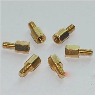
@nicofly974 Unfortunately I put this on hold for a while as I have been having a bit of trouble with my power option for the node. I am actually working on a solar power setup with a small charge controller and a 2x18650 battery pack. The solar panel setup will be on a servo controlled solar tracker that I will run from a separate pro mini. My two issues right now are that I am having some issues with the charge controller, possibly user error. The other issue is designing and 3D printing the parts that will hold the charge controller, battery pack and tracker. If this cheap charge controller is an issue and I have to get a different one, it may alter my design. Shipping on this controller took forever to come on the boat from China.
I haven't looked at my code for the sensors in a while, but maybe in the next day or two I'll post what I have with the understanding that it is in Alpha stage.
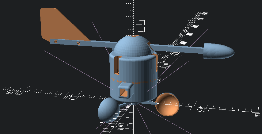
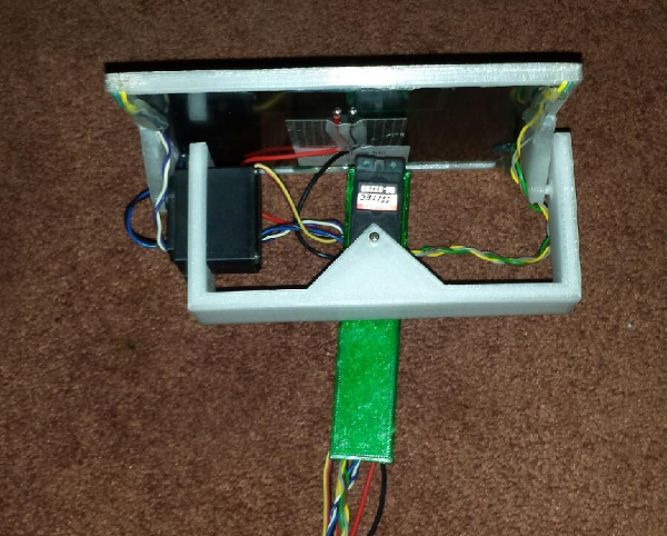
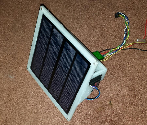
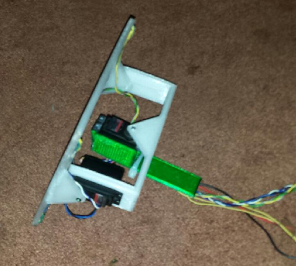
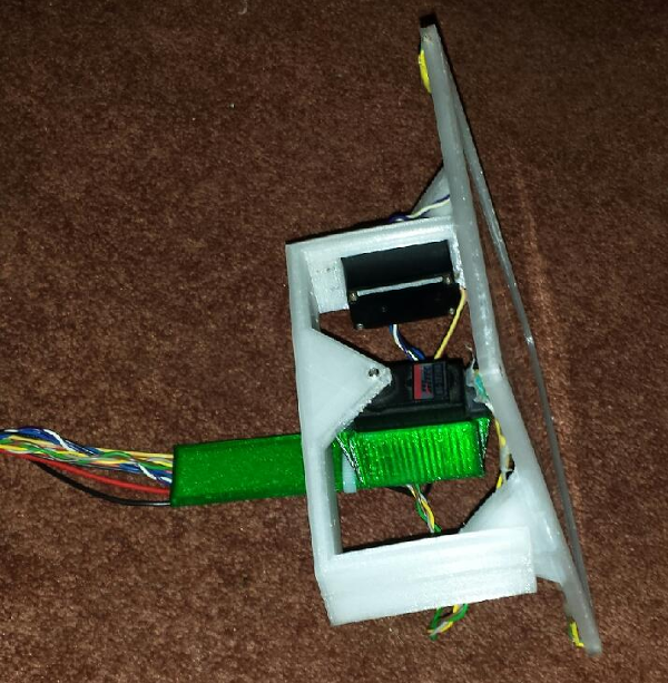
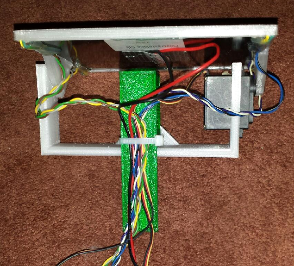
@dbemowsk Here are some pics of the dual axis solar tracker that I am working on for the weather station. In the 4 corners are the CDS photo cells for the tracker.
Vera Plus running UI7 with MySensors, Sonoffs and 1-Wire devices
Visit my website for more Bits, Bytes and Ramblings from me: http://dan.bemowski.info/ -
@dbemowsk Here are some pics of the dual axis solar tracker that I am working on for the weather station. In the 4 corners are the CDS photo cells for the tracker.
-
Hello,
For a project wtih a fablab, we have using a Li-Polymer Charge Management Controllers MCP73831
You can have free "sample" for prototype if you ask directly to the factory, perhaps it could be faster.