MySensors weather station
-
@dbemowsk you're right about the need for spi transactions on this one.
The sensor's spi interface gets initialized in the constructor and is overwritten by the radio. I understand your 'fix' will work, as you reinitialize the SPI bus everytime, as the transactions do in a portable way.
I have no time atm but I'll try to figure out the transaction settings when possible.@Yveaux Thanks. I have been trying to research it in the mean time, buy as of yet have not figured out how to do it. If you know of any websites that explain how to do it, it would help.I try to figure things out on my own because then I understand them better.
Thanks for all of the help you have given me on this.
Vera Plus running UI7 with MySensors, Sonoffs and 1-Wire devices
Visit my website for more Bits, Bytes and Ramblings from me: http://dan.bemowski.info/ -
@Yveaux Thanks. I have been trying to research it in the mean time, buy as of yet have not figured out how to do it. If you know of any websites that explain how to do it, it would help.I try to figure things out on my own because then I understand them better.
Thanks for all of the help you have given me on this.
@dbemowsk Let's break that line down, using the ATmega328P datasheet (pg. 221,222):
SPCR = (1<<SPE) | (1<<MSTR) | (1<<CPHA) | (1<<SPR1) | (1<<SPR0)- SPCR : SPI Control Register 0
- Bits not explicitly stated are 0, and can be read as (0<<xxx)
- (1<<SPE) : Enable SPI
- (0<<DORD) : Data order; here 0 to indicate MSB first
- (1<<MSTR) : Master/slave select; here 1 to indicate master
- (0<<CPOL): Clock polarity; here 0 to indicate SCK is low when idle
- (1<<CPHA) : Clock phase; here 1 to indicate sample on trailing edge
- (1<<SPR1) | (1<<SPR0) : Clock rate select; here 011 indicating Fosc/128
The SPISettings is used as follows:
SPISettings(clockrate, order, mode)- Let's start with the easy one: clockrate.
The driver above uses Fosc/128, which is 16000000/128=125000 for a 16MHz crystal. This seems a safe value as the AS5047 datasheet states tclk=100ns, so it can handle 10MHz. - Order is just the DORD parameter, so MSBFIRST.
- Then the tricky one: SPI_MODE
Here's an extensive explanation. It's a combination of clock phase and clock polarity. Luckily the datasheet states explicitly: "The AS5047D SPI uses mode=1 (CPOL=0, CPHA=1) to exchange data.", so use SPI_MODE1
Putting things together and wrapping SPI communication with transactions the result should be be:
uint32_t AS5047::read_register(uint32_t thisRegister)
{
    ....
    SPI.beginTransaction( SPISettings(125000, MSBFIRST, SPI_MODE1) );
    ....
    digitalWrite(_ss, LOW);
    SPI.transfer(highbyte); // first byte in
    ....
    digitalWrite(_ss, HIGH);
    SPI.endTransaction()
    ....
}
The clockrate can be increased if you like.
http://yveaux.blogspot.nl
-
@dbemowsk Let's break that line down, using the ATmega328P datasheet (pg. 221,222):
SPCR = (1<<SPE) | (1<<MSTR) | (1<<CPHA) | (1<<SPR1) | (1<<SPR0)- SPCR : SPI Control Register 0
- Bits not explicitly stated are 0, and can be read as (0<<xxx)
- (1<<SPE) : Enable SPI
- (0<<DORD) : Data order; here 0 to indicate MSB first
- (1<<MSTR) : Master/slave select; here 1 to indicate master
- (0<<CPOL): Clock polarity; here 0 to indicate SCK is low when idle
- (1<<CPHA) : Clock phase; here 1 to indicate sample on trailing edge
- (1<<SPR1) | (1<<SPR0) : Clock rate select; here 011 indicating Fosc/128
The SPISettings is used as follows:
SPISettings(clockrate, order, mode)- Let's start with the easy one: clockrate.
The driver above uses Fosc/128, which is 16000000/128=125000 for a 16MHz crystal. This seems a safe value as the AS5047 datasheet states tclk=100ns, so it can handle 10MHz. - Order is just the DORD parameter, so MSBFIRST.
- Then the tricky one: SPI_MODE
Here's an extensive explanation. It's a combination of clock phase and clock polarity. Luckily the datasheet states explicitly: "The AS5047D SPI uses mode=1 (CPOL=0, CPHA=1) to exchange data.", so use SPI_MODE1
Putting things together and wrapping SPI communication with transactions the result should be be:
uint32_t AS5047::read_register(uint32_t thisRegister)
{
    ....
    SPI.beginTransaction( SPISettings(125000, MSBFIRST, SPI_MODE1) );
    ....
    digitalWrite(_ss, LOW);
    SPI.transfer(highbyte); // first byte in
    ....
    digitalWrite(_ss, HIGH);
    SPI.endTransaction()
    ....
}
The clockrate can be increased if you like.
@Yveaux I cannot thank you enough. I tried these transaction settings and this worked perfectly. My hat is off to you.
Vera Plus running UI7 with MySensors, Sonoffs and 1-Wire devices
Visit my website for more Bits, Bytes and Ramblings from me: http://dan.bemowski.info/ -
@Yveaux I cannot thank you enough. I tried these transaction settings and this worked perfectly. My hat is off to you.
-
@dbemowsk great to hear!
I hope I managed to explain to you how to get to these values, as you wanted to learn from the process :+1: -
Hello
A friend send me an old weather station in 868mhz, I want to hack it for using it in domoticz
Your project is similar as I want, where can I find your code?
Thank's -
Hello
A friend send me an old weather station in 868mhz, I want to hack it for using it in domoticz
Your project is similar as I want, where can I find your code?
Thank's@nicofly974 Unfortunately I put this on hold for a while as I have been having a bit of trouble with my power option for the node. I am actually working on a solar power setup with a small charge controller and a 2x18650 battery pack. The solar panel setup will be on a servo controlled solar tracker that I will run from a separate pro mini. My two issues right now are that I am having some issues with the charge controller, possibly user error. The other issue is designing and 3D printing the parts that will hold the charge controller, battery pack and tracker. If this cheap charge controller is an issue and I have to get a different one, it may alter my design. Shipping on this controller took forever to come on the boat from China.
I haven't looked at my code for the sensors in a while, but maybe in the next day or two I'll post what I have with the understanding that it is in Alpha stage.
Vera Plus running UI7 with MySensors, Sonoffs and 1-Wire devices
Visit my website for more Bits, Bytes and Ramblings from me: http://dan.bemowski.info/ -
@nicofly974 Unfortunately I put this on hold for a while as I have been having a bit of trouble with my power option for the node. I am actually working on a solar power setup with a small charge controller and a 2x18650 battery pack. The solar panel setup will be on a servo controlled solar tracker that I will run from a separate pro mini. My two issues right now are that I am having some issues with the charge controller, possibly user error. The other issue is designing and 3D printing the parts that will hold the charge controller, battery pack and tracker. If this cheap charge controller is an issue and I have to get a different one, it may alter my design. Shipping on this controller took forever to come on the boat from China.
I haven't looked at my code for the sensors in a while, but maybe in the next day or two I'll post what I have with the understanding that it is in Alpha stage.
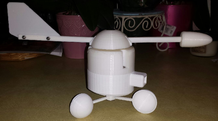
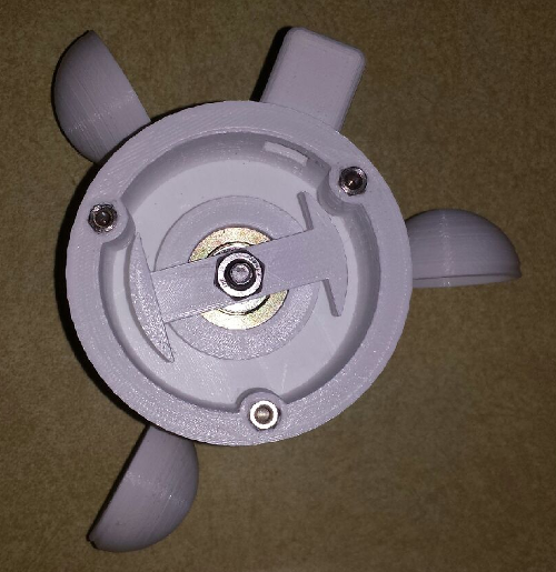
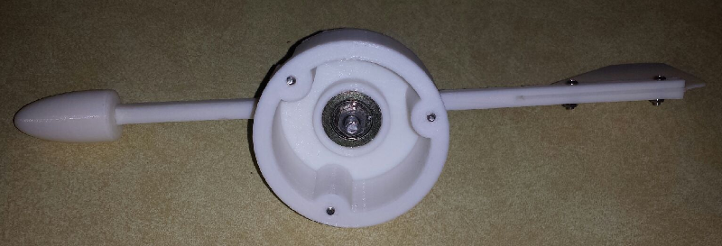
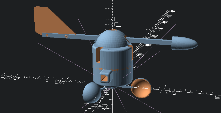
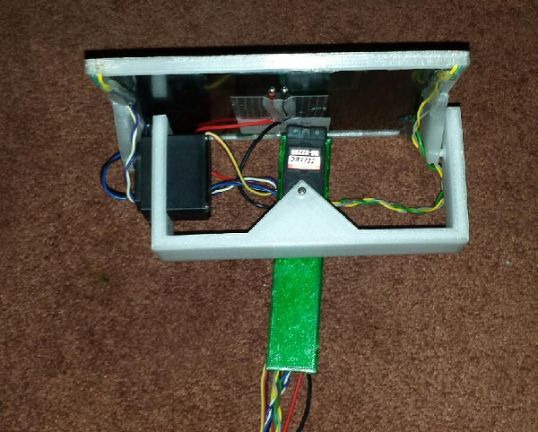
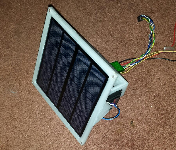
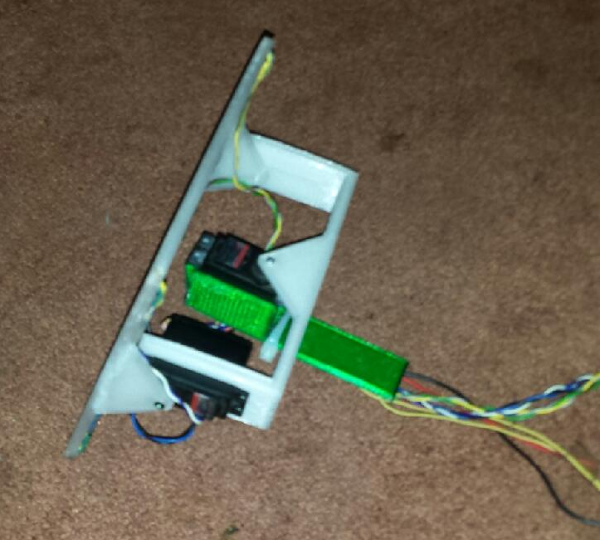
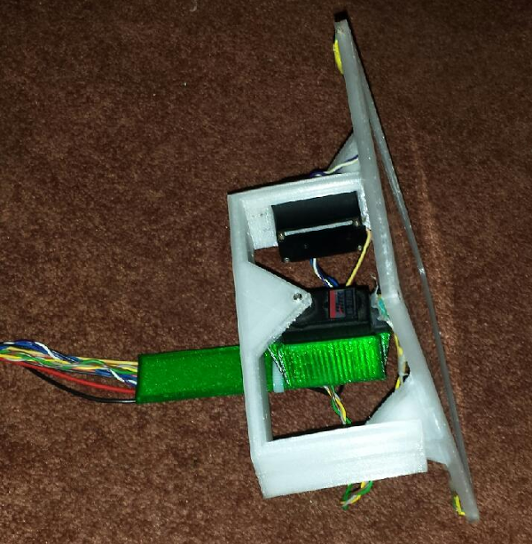
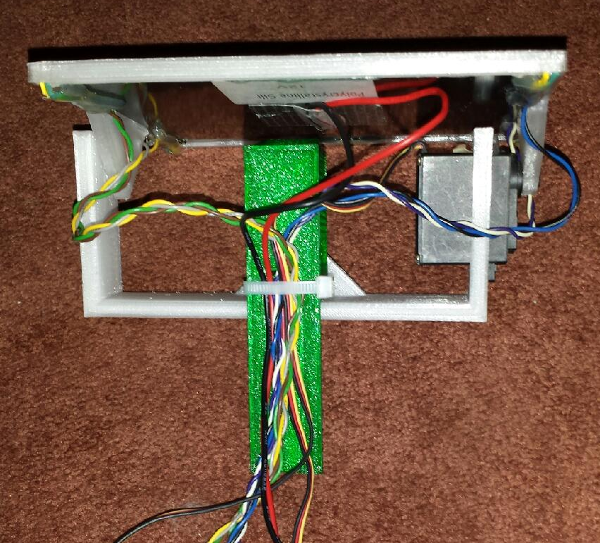
@dbemowsk Here are some pics of the dual axis solar tracker that I am working on for the weather station. In the 4 corners are the CDS photo cells for the tracker.
Vera Plus running UI7 with MySensors, Sonoffs and 1-Wire devices
Visit my website for more Bits, Bytes and Ramblings from me: http://dan.bemowski.info/ -
@dbemowsk Here are some pics of the dual axis solar tracker that I am working on for the weather station. In the 4 corners are the CDS photo cells for the tracker.
-
Hello,
For a project wtih a fablab, we have using a Li-Polymer Charge Management Controllers MCP73831
You can have free "sample" for prototype if you ask directly to the factory, perhaps it could be faster.