MySensors weather station
-
keep in mind that if you don't have a regulated voltage, the LED may change brightness as battery drains out. It just came to my mind: can you manage on the sw side 2 of your reed switches on at the same time? If you can find a way you can still use the magnet and add additional "half step" in your wind direction and make it more precise
@gohan My plan I think is going to be to have a solar panel that will charge a small LiPo or SLA battery. I would size the battery big enough to handle the regulator on the pro mini and use the regulated output voltage to run the LED to give it a constant brightness.
My original plan with the reed switches was to have the ability to trigger 2 reed switches at once. That was the reason for having 4 reed switches for N S E W and the other 4 for NE SE SW NW. I designed it to use 2 IO lines for the 2 different banks of 4 reed switches. That way if the N and NE reed switches were triggered that you would get that extra half step. The biggest problem that I am running into is that for some reason the reed switches don't seem to be triggering consistently with any of the magnet configurations I have tried. That is why I wanted to look at another approach.
I ordered the 10 photo transistors this morning. I will still look at a way to run them as 2 banks of 4 sensors like I did with the reed switches so I can get that extra half step.
-
I was referring exactly to that topic. Maybe you could ask Flopp if he could measure his part for you. The tricky part will be to find the right brightness for the LED when it is crossing between 2 phototransistor, but I think it will be easier to adjust than changing a magnetic field :)
About those parts, I can't say much, it is up to you: with 10 you still have 2 as spares just in case, 50 are quite a lot unless you plan to build more for your friends :)@gohan said in MySensors weather station:
The tricky part will be to find the right brightness for the LED when it is crossing between 2 photo-transistor, but I think it will be easier to adjust than changing a magnetic field :)
What I did for wind direction is that I "look" for the first photo-transistor that get light from the LED and use that direction. So I don't care if the light is crossing between 2 photo-transistor. I scan from first digital in until i scanned all of them.
void readWindDirection() { //check in what direction the wind is. First sensor that have light will be the direction int i = 4; for (i; i < 9 ; i++){ if (!digitalRead(i)){ WD = WDarray[i-4]; return; } } i = 14; for (i; i < 17 ; i++){ if (!digitalRead(i)){ WD = WDarray[i-9]; return; } } } -
@gohan said in MySensors weather station:
The tricky part will be to find the right brightness for the LED when it is crossing between 2 photo-transistor, but I think it will be easier to adjust than changing a magnetic field :)
What I did for wind direction is that I "look" for the first photo-transistor that get light from the LED and use that direction. So I don't care if the light is crossing between 2 photo-transistor. I scan from first digital in until i scanned all of them.
void readWindDirection() { //check in what direction the wind is. First sensor that have light will be the direction int i = 4; for (i; i < 9 ; i++){ if (!digitalRead(i)){ WD = WDarray[i-4]; return; } } i = 14; for (i; i < 17 ; i++){ if (!digitalRead(i)){ WD = WDarray[i-9]; return; } } }@flopp I am curious how you wired your electronics. I saw that as one of your original questions in your fody weather station post. so based on what you are saying, you really only use the 8 different directions, N, NE, E, SE, S, SW, W, NW, correct?
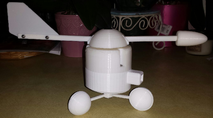
I have the basic design of the one you had pictured in your post mostly done. I still have to plan for circuit board mounting and wire connections, but I don't think that should be too difficult.
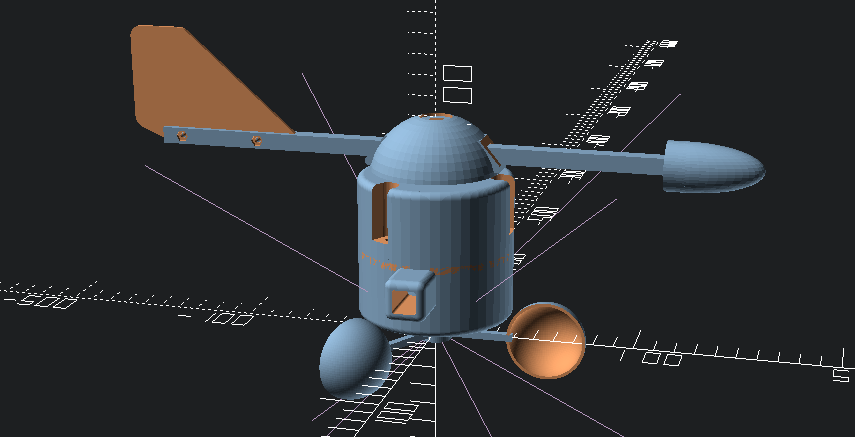
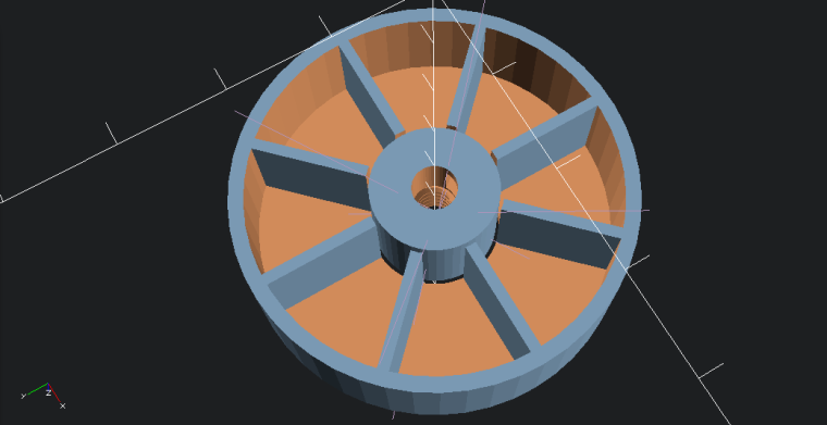
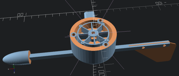
Here is my starting design done in OpenSCAD. I have the center hole threaded part way with a US 1/4 x 20 thread as that is what I used for the bolts to go through the wind vane.
I shoud be getting the phototransistors by Monday, so I want to draw up a preliminary design for the circuit board before that.
-
@flopp I am curious how you wired your electronics. I saw that as one of your original questions in your fody weather station post. so based on what you are saying, you really only use the 8 different directions, N, NE, E, SE, S, SW, W, NW, correct?
I have the basic design of the one you had pictured in your post mostly done. I still have to plan for circuit board mounting and wire connections, but I don't think that should be too difficult.
Here is my starting design done in OpenSCAD. I have the center hole threaded part way with a US 1/4 x 20 thread as that is what I used for the bolts to go through the wind vane.
I shoud be getting the phototransistors by Monday, so I want to draw up a preliminary design for the circuit board before that.
@dbemowsk said in MySensors weather station:
@flopp I am curious how you wired your electronics. I saw that as one of your original questions in your fody weather station post. so based on what you are saying, you really only use the 8 different directions, N, NE, E, SE, S, SW, W, NW, correct?
Yes, correct. I have 8 receivers for the light.
I want to know more about this product https://www.youtube.com/watch?v=-oQiJ50LcAc
-
@flopp I am curious how you wired your electronics. I saw that as one of your original questions in your fody weather station post. so based on what you are saying, you really only use the 8 different directions, N, NE, E, SE, S, SW, W, NW, correct?
I have the basic design of the one you had pictured in your post mostly done. I still have to plan for circuit board mounting and wire connections, but I don't think that should be too difficult.
Here is my starting design done in OpenSCAD. I have the center hole threaded part way with a US 1/4 x 20 thread as that is what I used for the bolts to go through the wind vane.
I shoud be getting the phototransistors by Monday, so I want to draw up a preliminary design for the circuit board before that.
@dbemowsk said in MySensors weather station:
Here is my starting design done in OpenSCAD. I have the center hole threaded part way with a US 1/4 x 20 thread as that is what I used for the bolts to go through the wind vane.
Your drawings look good.
-
Some things about the direction sensor, your magnet/reed switch is exactly what is in the old dallas 1-wire weather station and it worked well giving 16 positions,
the led/photodiode method mentioed by gohan is interesting, if you used analog inputs you could use the value across 3 of them at a time to interpolate a pretty high resolution answer, multiplexing could make it so you dont need 8 analog inputs.
Another thing is a rotary encoder, ive seen them used to measure the angles of telescope mounts, i believe they can be had with good enough resolution for your needs.
I didnt read the whole thread, apologies if i am repeating ideas, or if you have decided on a solution.
@wallyllama No problem, I appreciate the input.
-
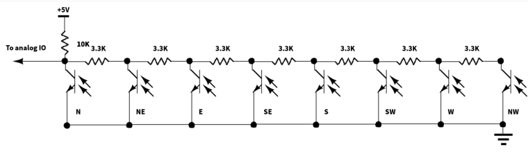
So for the phototransistor method, I figured I could use a similar approach to what I was planning with the reed switches. Here is a proposed schematic:
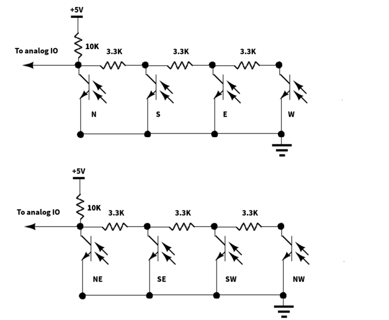
The idea is to use two identical banks of 4 phototransistors and alternating these in the slots. This should allow me to get the increased resolution that I was figuring on getting with the reed switch design.
Does anyone see any issues with this design?
-
So for the phototransistor method, I figured I could use a similar approach to what I was planning with the reed switches. Here is a proposed schematic:
The idea is to use two identical banks of 4 phototransistors and alternating these in the slots. This should allow me to get the increased resolution that I was figuring on getting with the reed switch design.
Does anyone see any issues with this design?
@dbemowsk
On my(fody) wind direction they use GND instead of VCC. When light is hitting the receiver, GND is passing through and you get a shortcut. I think, in that way you don't need all the 3,3K resistors.About resolution, personally I wouldn't focus on that because the wind is never in the same direction more than a few second then it moves a little bit. Maybe it stays in same direction when you have strong winds?
-
@dbemowsk
On my(fody) wind direction they use GND instead of VCC. When light is hitting the receiver, GND is passing through and you get a shortcut. I think, in that way you don't need all the 3,3K resistors.About resolution, personally I wouldn't focus on that because the wind is never in the same direction more than a few second then it moves a little bit. Maybe it stays in same direction when you have strong winds?
@flopp Are you only using 1 analog data line? The idea behind the resistors is to give varying degrees of 0 to 5 volts on the analog pin. Depending on which phototransistor is triggered, the value seen by the IO line is different for every one allowing you to differentiate which sensor is tripped.
If you are saying not to worry as much about the resolution, then I should be able to drop to using only 1 analog line instead of two with a configuration like this:
-
@dbemowsk
I am using 8 digital inputs, with pinmode(x,INPUT_PULLUP) on all of them, A0, A1 and A2 i use as digital input because I am using UNO so all the digitals was occupied with NRf and Rain, Wind speed.@flopp I just didn't want to use up all the IO lines if I didn't have to. The designs that I was showing with the resistors allows you to detect multiple switch triggers with 1 or 2 I/O lines depending how you want that detection done. I want to add a few other sensors to the setup, so I want to keep as many IO lines free as I can.
-
Just got my phototransistors. The ebay auction said that it was for 10 sensors. I got 15..... BONUS. :^)
-
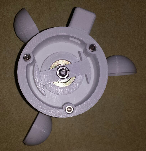
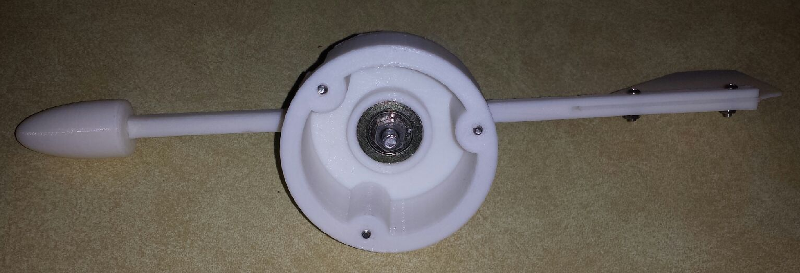
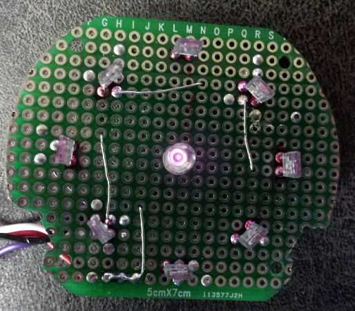
OK, so I am doing some testing on the new wind direction sensor board I am building. My problem is that the infrared LED that I have, which was scavanged from an old remote, has good IR pointing forward. but when I try to direct it sideways to the IR sensors, I appear to not be getting enough IR light to trigger the sensors. If I shine a flashlight at each of the sensors, they register, but not when O Does anyone know of either a different IR diode, or a way that I can get the existing diode to shine more in a sideways direction? Here is what the board is looking like. I currently only have one set of 4 sensors connected for testing. You can kind of see that the IR LED is lit.
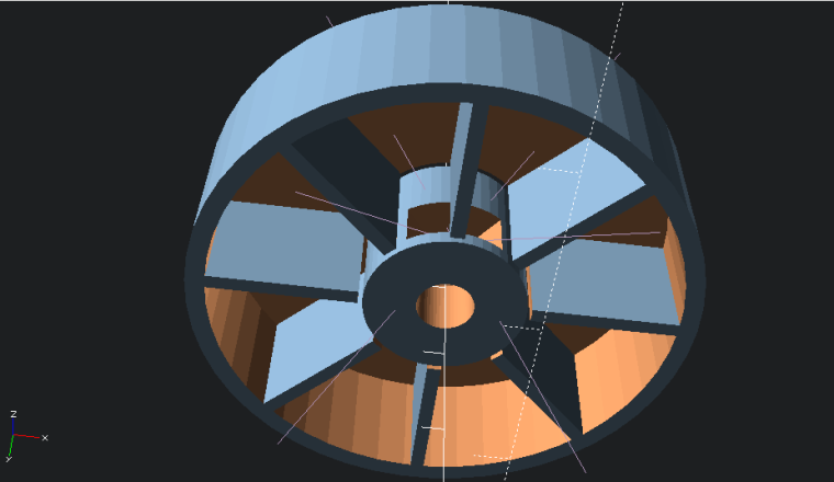
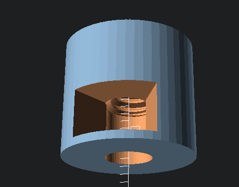
This is the design of the IR rotor that directs the light which gets screwed to the end of the bolt that is the shaft of the wind direction vane. The majority of the IR light gets directed at the end of the bolt.
 .
.I am up for any suggestions.
Vera Plus running UI7 with MySensors, Sonoffs and 1-Wire devices
Visit my website for more Bits, Bytes and Ramblings from me: http://dan.bemowski.info/ -
Just got my phototransistors. The ebay auction said that it was for 10 sensors. I got 15..... BONUS. :^)
@dbemowsk 15 is metric for 10.*
- If you received 16, then I could have said you ordered in hex, and this would actually have been funny.
-
OK, so I am doing some testing on the new wind direction sensor board I am building. My problem is that the infrared LED that I have, which was scavanged from an old remote, has good IR pointing forward. but when I try to direct it sideways to the IR sensors, I appear to not be getting enough IR light to trigger the sensors. If I shine a flashlight at each of the sensors, they register, but not when O Does anyone know of either a different IR diode, or a way that I can get the existing diode to shine more in a sideways direction? Here is what the board is looking like. I currently only have one set of 4 sensors connected for testing. You can kind of see that the IR LED is lit.
This is the design of the IR rotor that directs the light which gets screwed to the end of the bolt that is the shaft of the wind direction vane. The majority of the IR light gets directed at the end of the bolt.
.I am up for any suggestions.
@dbemowsk i have an led flashlight in the shape of a lantern, it has a shape like cone that has been dehydrated, so there is a concave curve from the base to the tip. Sort of like a golf tee but different proportions.

I guess it it like a regular flashlight reflector inside out
-
@dbemowsk 15 is metric for 10.*
- If you received 16, then I could have said you ordered in hex, and this would actually have been funny.
@wallyllama That would have been funny. There are 10 types of people in this world, Those that understand binary, and those that don't.
Hello! It looks like you're interested in this conversation, but you don't have an account yet.
Getting fed up of having to scroll through the same posts each visit? When you register for an account, you'll always come back to exactly where you were before, and choose to be notified of new replies (either via email, or push notification). You'll also be able to save bookmarks and upvote posts to show your appreciation to other community members.
With your input, this post could be even better 💗
Register Login