Has anyone made their own lab power supply out of a PSU?
-
I just bought an ATX breakout board that can be connected to the 24 pin cable from an old power supply. It has bindings post with gnd, 3.3V, 5V and 12V. Very easy (and safe) to use and set up.
-
I just bought an ATX breakout board that can be connected to the 24 pin cable from an old power supply. It has bindings post with gnd, 3.3V, 5V and 12V. Very easy (and safe) to use and set up.
@LastSamurai Great idea, just ordered one from ebay
-
Well, if you only need static voltages: 12 and 5 you already have and for 3.3 I'd get LM2596 or XM1584 regulators depending on current needs. But then, this would not really be a lab PSU which is by definition adjustable ;) A common design is the EEVBlog one. Nasty stuff though, I honestly wouldn't do it myself and rather spend the 150EUR...
@pansen Then you would miss the fun and flexibility ;-) . A good combination of cheap available stuff in combination with (adjustable) linear components is giving me everything I need.
- The ATX fixed voltages (heavily "denoised") for most MySensors and LED stuff (3.3, 5, 12, > 5 Amps)
- An adjustable (and programmable) linear supply (fed by the ATX) like µSupply.
-
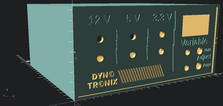
I happen to be in the middle of making one right now. I have kind of been working on it slowly in between my weather sensor project. I am using an ATX supply that I pulled from an old computer to give me 12V, 5V and 3.3V, and then I plan on also having a variable supply. For the variable supply I am using a buck converter with a current and voltage meter. I will steal one of the 12 volt legs from the ATX supply to run the buck converter for the variable supply.
Here is my 3D design for the unit.
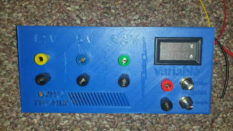
I have the front panel printed, I just have to find the time to print the outer shell and the back panel. Here is what the front panel looks like with some of the components dry fitted.
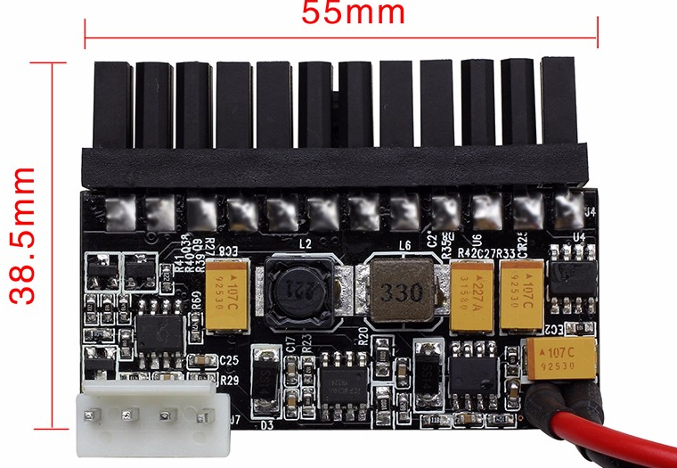
This is the buck converter that I got from ebay and these are the multi-turn pots that I bought that I will use to replace the small on-board ones that are on the buck converter for voltage and current adjustment. The last thing is the voltage and current meter/display. This is the one that I bought on ebay.
The most expensive parts were the multi-turn pots. I got mine $2 cheaper per pot than they have them listed for now. I had a hard time finding anything cheap that was panel mountable. As I said, this is a slow work in progress project that I think will be pretty useful once I get it done.
-
Sorry if I'm showing my ignorance here, but I recall the ATX series having both -12v and +12v supply lines, giving 24v differential (Ok, you would need to insulate the -12v against case earth). Why did you opt for the buck/boost rather than an LM317 and current bypass transistors up to ca 23v ? Current requirements?
@zboblamont It was an easy connect and go solution rather than having to build something with an LM317 and other components.
-
I would love to see a project thread about making this...
Hello! It looks like you're interested in this conversation, but you don't have an account yet.
Getting fed up of having to scroll through the same posts each visit? When you register for an account, you'll always come back to exactly where you were before, and choose to be notified of new replies (either via email, or push notification). You'll also be able to save bookmarks and upvote posts to show your appreciation to other community members.
With your input, this post could be even better 💗
Register Login