RGB LED strip

-
@sundberg84 I have version 3.3B. I always thought that this is the correct power connection if the source voltage is more than 3.3 V. And with this power connection I wanted to avoid using a separate voltage regulator for the radio module. If I feed 5V to the VCC input, will there be a logic signal on the terminals 3.3V or 5V? And will not this be detrimental to the controller?
@vladimir - ah sorry, my misstake. Didnt see the 3.3v there.
Strange your chip is getting hot... is there some solder-bridge that shorts something? A bad capacitor? Can you measure resistance between VCC and GND?Controller: Proxmox VM - Home Assistant
MySensors GW: Arduino Uno - W5100 Ethernet, Gw Shield Nrf24l01+ 2,4Ghz
MySensors GW: Arduino Uno - Gw Shield RFM69, 433mhz
RFLink GW - Arduino Mega + RFLink Shield, 433mhz -
@vladimir - ah sorry, my misstake. Didnt see the 3.3v there.
Strange your chip is getting hot... is there some solder-bridge that shorts something? A bad capacitor? Can you measure resistance between VCC and GND?@sundberg84 said in RGB LED strip:
Can you measure resistance between VCC and GND?
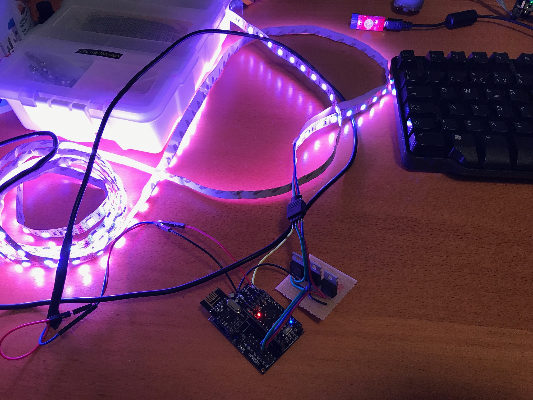
I completely rebuilt the whole scheme, I used the new components. This time I used Arduino Nano. Connect power to terminal 5V. The situation is repeated again, the microcontroller becomes very hot. But only when the light is on.
Honestly, I never measured the resistance. I hope everything was done right.

-
@sundberg84 said in RGB LED strip:
Can you measure resistance between VCC and GND?
I completely rebuilt the whole scheme, I used the new components. This time I used Arduino Nano. Connect power to terminal 5V. The situation is repeated again, the microcontroller becomes very hot. But only when the light is on.
Honestly, I never measured the resistance. I hope everything was done right.
@vladimir not sure about this. Make sure you connected the digital pins to the gate (left pin on irlz44). I don't know why the IC should get hot unless you draw alot of current.
Controller: Proxmox VM - Home Assistant
MySensors GW: Arduino Uno - W5100 Ethernet, Gw Shield Nrf24l01+ 2,4Ghz
MySensors GW: Arduino Uno - Gw Shield RFM69, 433mhz
RFLink GW - Arduino Mega + RFLink Shield, 433mhz -
@vladimir not sure about this. Make sure you connected the digital pins to the gate (left pin on irlz44). I don't know why the IC should get hot unless you draw alot of current.
@sundberg84 Sorry... I incorrectly connected IRLZ44.:man-facepalming: :smile: But last time they were connected correctly. Now everything works well. Only LM2940 slightly heats up, according to my subjective sensations, up to 60-70 degrees. This is normal?
I am very grateful for your help!:raised_hands: -
@sundberg84 Sorry... I incorrectly connected IRLZ44.:man-facepalming: :smile: But last time they were connected correctly. Now everything works well. Only LM2940 slightly heats up, according to my subjective sensations, up to 60-70 degrees. This is normal?
I am very grateful for your help!:raised_hands:@vladimir LM2940 has recommended limit of 125dgr c. 60dgr should be just fine... but still a bit strange since this is rated for 1A and only powers the atmega328p. The current should come directly from the 12v source.
Controller: Proxmox VM - Home Assistant
MySensors GW: Arduino Uno - W5100 Ethernet, Gw Shield Nrf24l01+ 2,4Ghz
MySensors GW: Arduino Uno - Gw Shield RFM69, 433mhz
RFLink GW - Arduino Mega + RFLink Shield, 433mhz -
@vladimir LM2940 has recommended limit of 125dgr c. 60dgr should be just fine... but still a bit strange since this is rated for 1A and only powers the atmega328p. The current should come directly from the 12v source.
@sundberg84 At this time, everything is collected on a plastic prototyping board, in the evening I will move all the components to a breadboard from a textolite, perhaps there will be better results.:thinking_face:
-
Well, it took some time, but here is v1.8 at last!
I have modified the code to handle RGBW strips, since I realized that the white light from RGB strips is very uncomfortable and not really suitable for general illumination. It should be fairly easy to convert it back to RGB though. Adding the W channel means that I now need 4 PWM pins, and therefore it was necessary to redefine one of the pins that the radio is connected to - the sketch now expects CE to be connected to pin 8 instead of 9 which is the default (a pro mini only has 3 free PWM pins if you use the default setup).
I've also completely changed now programs/modes are implemented so it should be easier to add new programs. Feel free to experiment with this and let me know what you think.
/** * This program is free software; you can redistribute it and/or * modify it under the terms of the GNU General Public License * version 2 as published by the Free Software Foundation. * * LED STRIP sketch for Mysensors ******************************* * * REVISION HISTORY * 1.0 * Based on the example sketch in mysensors * 1.1 * prgspeed parameter (send as V_VAR1 message) * HomeAssistant compatible (send status to ack) * 1.2 * OTA support * 1.3 * Power-on self test * 1.4 * Bug fix * 1.5 * Other default values * 1.6 * Repeater feature * 1.7 * Multitasking. Alarm and RELAX modes. * 1.8 * Reengineered programs/modes logic. * RGBW variant. Requires 4 PWM pins, so we need to move use a different pin for one of radio connections. */ #define MY_OTA_FIRMWARE_FEATURE // #define MY_REPEATER_FEATURE #define MY_NODE_ID AUTO #define MY_RADIO_NRF24 //#define MY_DEBUG // Normally the radio uses pin 9 for CE #define MY_RF24_CE_PIN 8 #include <MySensors.h> #define CHILD_ID_LIGHT 1 #define SN "LED Strip" #define SV "1.8" MyMessage lightMsg(CHILD_ID_LIGHT, V_LIGHT); MyMessage rgbwMsg(CHILD_ID_LIGHT, V_RGBW); MyMessage dimmerMsg(CHILD_ID_LIGHT, V_DIMMER); MyMessage prgspeedMsg(CHILD_ID_LIGHT, V_VAR1); MyMessage programMsg(CHILD_ID_LIGHT, V_VAR2); #define RR 0 #define GG 1 #define BB 2 #define WW 3 byte current[] = {255, 255, 255, 255}; byte target[] = {255, 255, 255, 255}; byte save[] = {0, 0, 0, 0}; byte temp[] = {0, 0, 0, 0}; float delta[] = {0.0, 0.0, 0.0, 0.0}; char rgbwstring[] = "000000ff"; int on_off_status = 0; int dimmerlevel = 100; int prgspeed = 20; unsigned long last_update = 0; unsigned long tick_length = 5; int fade_step = 0; int program_timer; int program_cycle; int program_step; // Make sure these are PWM pins #define REDPIN 6 #define GREENPIN 5 #define BLUEPIN 3 #define WHITEPIN 9 #define LIGHT_NORMAL 0 #define LIGHT_FADING 1 #define PROGRAM_NOP 0 int light_mode = LIGHT_NORMAL; int program_mode = PROGRAM_NOP; #define SET 0 #define SET_AND_WAIT 1 #define SET_RANDOM 2 #define SET_RANDOM_AND_WAIT 3 #define FADE 4 #define FADE_RANDOM 5 #define WAIT 6 typedef struct rgb_cmd { byte cmd; int p; byte rgbw[4]; } rgb_cmd; rgb_cmd program_ALARM[] = { {SET_AND_WAIT, 25, {255, 255, 255, 0}}, {SET_AND_WAIT, 25, {0, 0, 0, 0}}, {SET_AND_WAIT, 25, {0, 0, 0, 255}}, {SET_AND_WAIT, 25, {0, 0, 0, 0}} }; rgb_cmd program_RELAX[] = { {FADE, 1000, {255, 32, 0, 0}}, {FADE, 1000, {255, 32, 16, 0}}, {FADE, 1000, {255, 16, 32, 0}}, {FADE, 1000, {255, 128, 0, 0}}, {FADE, 1000, {255, 32, 0, 0}}, {FADE, 1000, {255, 32, 32, 0}}, {FADE, 1000, {255, 0, 32, 0}} }; rgb_cmd program_PARTY[] = { {SET_AND_WAIT, 10, {255, 0, 0, 0}}, {SET_AND_WAIT, 10, {0, 0, 0, 255}}, {SET_AND_WAIT, 10, {255, 0, 0, 0}}, {SET_AND_WAIT, 10, {0, 0, 0, 255}}, {SET_AND_WAIT, 10, {255, 0, 0,0}}, {SET_AND_WAIT, 10, {0, 0, 0, 255}}, {SET_AND_WAIT, 10, {255, 0, 0,0}}, {SET_AND_WAIT, 10, {0, 0, 0, 255}}, {SET_AND_WAIT, 10, {255, 0, 0, 0}}, {SET_AND_WAIT, 10, {0, 0, 0, 255}}, {FADE_RANDOM, 50, {255, 255, 255, 0}}, {FADE_RANDOM, 50, {255, 255, 255, 0}}, {FADE_RANDOM, 50, {255, 255, 255, 0}}, {FADE_RANDOM, 50, {255, 255, 255, 0}}, {SET_AND_WAIT, 50, {0, 0, 255, 0}}, {SET_AND_WAIT, 50, {0, 255, 255 ,0}}, {SET_AND_WAIT, 50, {255, 255, 0, 0}}, {SET_AND_WAIT, 50, {0, 255, 0, 0}}, {FADE_RANDOM, 50, {255, 255, 255, 0}}, {FADE_RANDOM, 50, {255, 255, 255, 0}}, {FADE_RANDOM, 50, {255, 255, 255, 0}}, {FADE_RANDOM, 50, {255, 255, 255, 0}}, {FADE_RANDOM, 50, {255, 255, 255, 0}} }; rgb_cmd* programs[] = { &program_ALARM[0], &program_RELAX[0], &program_PARTY[0] }; const int program_steps[] = { sizeof(program_ALARM)/sizeof(rgb_cmd), 7, 22 }; void setup() { // Fix the PWM timer. Without this the LEDs will flicker. TCCR0A = _BV(COM0A1) | _BV(COM0B1) | _BV(WGM00); // Output pins pinMode(REDPIN, OUTPUT); pinMode(GREENPIN, OUTPUT); pinMode(BLUEPIN, OUTPUT); pinMode(WHITEPIN, OUTPUT); } void presentation() { // Send the Sketch Version Information to the Gateway sendSketchInfo(SN, SV); present(CHILD_ID_LIGHT, S_RGBW_LIGHT); } void selftest() { on_off_status = 1; current[RR] = 255; current[GG] = 0; current[BB] = 0; current[WW] = 0; set_hw_status(); wait(200); current[RR] = 0; current[GG] = 255; set_hw_status(); wait(200); current[GG] = 0; current[BB] = 255; set_hw_status(); wait(200); current[BB] = 0; current[WW] = 255; set_hw_status(); wait(200); current[RR] = 0; current[GG] = 0; current[BB] = 0; set_hw_status(); wait(200); on_off_status = 0; } void loop() { static bool first_message_sent = false; if ( first_message_sent == false ) { selftest(); set_hw_status(); send(rgbwMsg.set(rgbwstring)); send(lightMsg.set(on_off_status)); send(dimmerMsg.set(dimmerlevel)); send(prgspeedMsg.set(prgspeed)); send(programMsg.set(program_mode)); first_message_sent = true; } unsigned long now = millis(); // Maybe we wrapped around? Then reset last_update to 0. if (now < last_update) { last_update = 0; } if (now - last_update > tick_length) { last_update = now; // If we're fading, finish that before we do anything else if (light_mode == LIGHT_FADING) { calc_fade(); } else { if (program_mode > PROGRAM_NOP) { handle_program(); } } } set_hw_status(); } void receive(const MyMessage &message) { int val; if (message.type == V_RGBW) { for (int i=0; i<=3; i++) { temp[i] = hextoint(message.data[i*2]) * 16 + hextoint(message.data[i*2+1]); } // Save old value strcpy(rgbwstring, message.data); init_fade(prgspeed, temp); send(rgbwMsg.set(rgbwstring)); } else if (message.type == V_LIGHT || message.type == V_STATUS) { val = atoi(message.data); if (val == 0 or val == 1) { on_off_status = val; send(lightMsg.set(on_off_status)); } } else if (message.type == V_PERCENTAGE) { val = atoi(message.data); if (val >= 0 and val <=100) { dimmerlevel = val; send(dimmerMsg.set(dimmerlevel)); } } else if (message.type == V_VAR1 ) { val = atoi(message.data); if (val >= 0 and val <= 2000) { prgspeed = val; send(prgspeedMsg.set(val)); } } else if (message.type == V_VAR2 ) { val = atoi(message.data); if (val == PROGRAM_NOP) { stop_program(); send(programMsg.set(val)); } else { init_program(val); send(programMsg.set(val)); } } else { return; } } void execute_step(rgb_cmd cmd) { if (cmd.cmd == SET) { set_rgb(cmd.rgbw); } else if (cmd.cmd == SET_AND_WAIT) { set_rgb(cmd.rgbw); program_timer = cmd.p; } else if (cmd.cmd == SET_RANDOM) { set_rgb_random(cmd.rgbw); } else if (cmd.cmd == SET_RANDOM_AND_WAIT) { set_rgb_random(cmd.rgbw); program_timer = cmd.p; } else if (cmd.cmd == FADE) { init_fade(cmd.p, cmd.rgbw); } else if (cmd.cmd == FADE_RANDOM) { init_fade_random(cmd.p, cmd.rgbw); } else if (cmd.cmd == WAIT) { program_timer = cmd.p; } } void init_program(int program) { program_mode = program; program_step = 0; program_timer = 0; save_state(); execute_step(programs[program_mode-1][0]); } void handle_program() { if (program_timer > 0) { program_timer--; } if (program_timer == 0) { program_step++; if (program_step == program_steps[program_mode-1]) { program_step = 0; } execute_step(programs[program_mode-1][program_step]); } } void stop_program() { restore_state(); light_mode = LIGHT_NORMAL; program_mode = PROGRAM_NOP; } void save_state() { memcpy(save, current, 4 ); } void restore_state() { memcpy(current, save, 4 ); } void set_rgb (byte rgbw[]) { light_mode = LIGHT_NORMAL; memcpy(current, rgbw, 4); } void set_rgb_random (byte rgbw[]) { light_mode = LIGHT_NORMAL; for (int i=0; i <= 3; i++){ current[i] = random(rgbw[i]); } } void init_fade(int t, byte rgbw[]) { light_mode = LIGHT_FADING; fade_step = t; memcpy(target, rgbw, 4); for (int i=0; i<=3; i++) { delta[i] = (target[i] - current[i]) / float(fade_step); } } void init_fade_random(int t, byte rgbw[]) { light_mode = LIGHT_FADING; fade_step = t; for (int i=0; i<=3; i++) { target[i] = random(rgbw[i]); delta[i] = (target[i] - current[i]) / float(fade_step); } } void calc_fade() { if (fade_step > 0) { fade_step--; for (int i=0; i<=3; i++) { current[i] = target[i] - delta[i] * fade_step; } } else { light_mode = LIGHT_NORMAL; } } void set_hw_status() { analogWrite(REDPIN, on_off_status * (int)(current[RR] * dimmerlevel/100.0)); analogWrite(GREENPIN, on_off_status * (int)(current[GG] * dimmerlevel/100.0)); analogWrite(BLUEPIN, on_off_status * (int)(current[BB] * dimmerlevel/100.0)); analogWrite(WHITEPIN, on_off_status * (int)(current[WW] * dimmerlevel/100.0)); } byte hextoint (byte c) { if ((c >= '0') && (c <= '9')) return c - '0'; if ((c >= 'A') && (c <= 'F')) return c - 'A' + 10; if ((c >= 'a') && (c <= 'f')) return c - 'a' + 10; return 0; } -
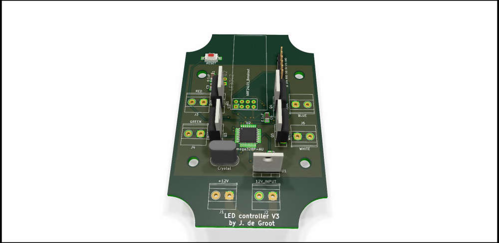
Wanted to leave this here I currently created this PCB to work with @maghac his code. The prototype on the breadboard worked so now it is being produced. As soon as I have a working model I will post the gerber files so anybody interested can also order it for manufacturing. The weird shape by the way is because of a enclosure I am using this one (the 100 X 68 X 50).
-
I have been researching controlling LEDs and this seems one of the better threads on MySensors with links to all the relevant related projects (this @maghac OP one for analog RGB, @LastSamurai RGBW alternative, @dmonty for digital, @ikkeT and others' improvements, and finally @Jim-de-Groot latest board; sorry if I left anyone out). Thanks to everyone for sharing your work!
So I will ask here a variation of what I I asked @LastSamurai in his thread: Are all of you still using these MySensors based nodes?
Because I initially started thinking to use a MySensors based solution because I thought Wi-Fi based ones (although arguably easier, cheaper) like MagicHome controllers would be "too slow" but @LastSamurai seemed to state that he changed from MySensors because it was "too slow" in responding.
Or maybe the reasons are not speed / response time related? Maybe you guys didn't like that interface? Or maybe they were not as readily and cheaply available back when this post began (may 2017)? Or maybe people just like to tinker (I get it, some times I do too)?
But right now I am thinking about ordering some of those MagicHome devices just to play around with, they are only few dollars each on AliExpress instead of dorking around ordering boards, figuring out correct mosfets to use, implementing software, etc...
What am I missing here?
I am not trying to be contrary! I honestly want to know! :D
Hello! It looks like you're interested in this conversation, but you don't have an account yet.
Getting fed up of having to scroll through the same posts each visit? When you register for an account, you'll always come back to exactly where you were before, and choose to be notified of new replies (either via email, or push notification). You'll also be able to save bookmarks and upvote posts to show your appreciation to other community members.
With your input, this post could be even better 💗
Register Login