💬 RFM69 Livolo 2 channels 1 way EU switch(VL-C700X-1_Ver_C2)
-
@tonnerre33 well, the reason for that is that livolo switch power circuit board contains two power circuits :)
One is a standby power which feeds the MC while all lamps are off and another one is the circuit that powers the whole system while at least one of the lamps is on (for two lamps switch).@Tigroenot Thank you for your comment.
I understand there is 2 power circuits, but i don't understand why the mosfet burnt, after wire a bridge across the 100K resistor and after few commands (not immediatly).I did many simulations with LTspice and i didn't find the reason...
I think he has burnt when i have the lamp 1 on and i have pushed on the other button without lamp 2 connected on the livolo.
If someone have any idea, that's will be helpfull for not burn another mofset. ^^
Now i'am waiting the deliveri of the mofset and i am hoping that is the HS component ;)
-
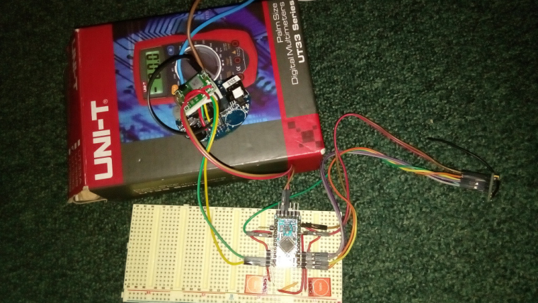
Good news everyone! I managed to set up a test board in order to verify the new Livolo relays/power board and with the required modifications IT WORKS!!! as the previous one did from my old project. This time only 2 modifications are required on the board instead of 3 because the 12-14V supply is already connected now to the 2x7 connector.
I expected this to work as the power/relays board didn't changed - they placed the same set of components but in some different places and I was able to recognize the base layout.
@tonnerre33 Maybe yo wired something wrong..but for me it worked from the start. I will post here images and test results so stay tuned.
There you have it in action(sorry for my phone camera and delays): MySensors Livolo in action
Power/relays board required modifications(red lines represent wires - you could desolder those components too and just put some solder/wire bridges)
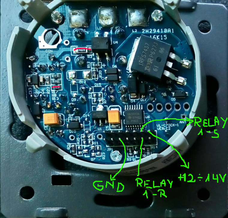
Next as seen in the video I wired a cheap dc-dc step down converter bought from Aliexpress to the 12-14V pin from the connector and ground and used its 3.3V output to power up the arduino pro mini board. The RELAY 1 - S and 1- R pins mean: channel 1(or 2 - it doesn't matter as the channels are identical) Set and Reset(because we have bi-stable relays). Those were wired to some digital outputs on arduino pro mini as seen here:
-
Good news everyone! I managed to set up a test board in order to verify the new Livolo relays/power board and with the required modifications IT WORKS!!! as the previous one did from my old project. This time only 2 modifications are required on the board instead of 3 because the 12-14V supply is already connected now to the 2x7 connector.
I expected this to work as the power/relays board didn't changed - they placed the same set of components but in some different places and I was able to recognize the base layout.
@tonnerre33 Maybe yo wired something wrong..but for me it worked from the start. I will post here images and test results so stay tuned.
There you have it in action(sorry for my phone camera and delays): MySensors Livolo in action
Power/relays board required modifications(red lines represent wires - you could desolder those components too and just put some solder/wire bridges)
Next as seen in the video I wired a cheap dc-dc step down converter bought from Aliexpress to the 12-14V pin from the connector and ground and used its 3.3V output to power up the arduino pro mini board. The RELAY 1 - S and 1- R pins mean: channel 1(or 2 - it doesn't matter as the channels are identical) Set and Reset(because we have bi-stable relays). Those were wired to some digital outputs on arduino pro mini as seen here:
@mtiutiu Did you try with only a brige on the 100K resistor ?
Which type of lamp and power did you use ? -
@mtiutiu Did you try with only a brige on the 100K resistor ?
Which type of lamp and power did you use ?CFL - 15W. No, I wired both bridges.
Here's a quick block diagram for the whole circuit. I hope that I didn't missed anything or wired wrong there.
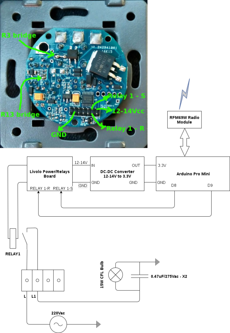
Well in reality the internal relay contact is not wired like in my diagram but to some extra circuits in order to provide voltage when the switch is closed - this is just a quick and dirty overview of the system.
The test circuit is working now for more than an hour with no problems. Oh..and the old project that I made for Livolo is in production now for more than a month and it works flawlessly.
I tested both CFL and LED bulbs - 5W was the lowest that I tried and it worked perfectly in both cases. The important part here is the parallel capacitor across the light bulb which gives the extra current that the standby circuit needs from the Livolo board in order to power the whole thing. The most sensitive part is the standby circuit because in that case the light bulb is OFF and it cannot provide enough current in this state - this is obvious because the load which is in series is turned off so only a small amount of current is present in the series circuit.
This works for the original board because the touch sensing part draws very little current(under a 1mA I think) and the radio receiver (in the RC variant) which they use draws 5mA or so. This compared with MySensors RFM69W which draws 60mA peak and on average 20-30mA or so.
-
CFL - 15W. No, I wired both bridges.
Here's a quick block diagram for the whole circuit. I hope that I didn't missed anything or wired wrong there.
Well in reality the internal relay contact is not wired like in my diagram but to some extra circuits in order to provide voltage when the switch is closed - this is just a quick and dirty overview of the system.
The test circuit is working now for more than an hour with no problems. Oh..and the old project that I made for Livolo is in production now for more than a month and it works flawlessly.
I tested both CFL and LED bulbs - 5W was the lowest that I tried and it worked perfectly in both cases. The important part here is the parallel capacitor across the light bulb which gives the extra current that the standby circuit needs from the Livolo board in order to power the whole thing. The most sensitive part is the standby circuit because in that case the light bulb is OFF and it cannot provide enough current in this state - this is obvious because the load which is in series is turned off so only a small amount of current is present in the series circuit.
This works for the original board because the touch sensing part draws very little current(under a 1mA I think) and the radio receiver (in the RC variant) which they use draws 5mA or so. This compared with MySensors RFM69W which draws 60mA peak and on average 20-30mA or so.
@mtiutiu Thx for the answers ;)
I think you have a mistake on your picture. The GND pin is the second pin of the bottom when you start by the left side ;)Did you test both relays in Set position (simulate 2 lamps power on even if one isn't connected) ?
-
@mtiutiu Thx for the answers ;)
I think you have a mistake on your picture. The GND pin is the second pin of the bottom when you start by the left side ;)Did you test both relays in Set position (simulate 2 lamps power on even if one isn't connected) ?
Yes it seems that the gnd pin is shifted by one position to the right. I will fix that - thanks for noticing. I will do the test with the other channel too. It's sufficient to have one light bulb and capacitor to trigger the other channel too.
-
Fixed the diagram posted earlier and now the required solder bridges are visible(R3 and R13 needs to be replaced by a solder/wire bridge as seen in the picture).
This is valable only for the VL-C700X-1 VER: C2 livolo power/relays board hw revision only!
-
Yes it seems that the gnd pin is shifted by one position to the right. I will fix that - thanks for noticing. I will do the test with the other channel too. It's sufficient to have one light bulb and capacitor to trigger the other channel too.
@mtiutiu Yes if you can just test the two channels on with only one bulb and capacitor this would be great
-
@mtiutiu Yes if you can just test the two channels on with only one bulb and capacitor this would be great
Ok so this board is basically the same board and it has the same set of components as the previous one(the old one from the old project that I've made) so it should work with both channels or in whatever combination you want. They only changed some components location - that's all. For now I don't know when I'll have time to test - I think only when my boards will arrive from the manufacturer.
-
@mtiutiu Yes if you can just test the two channels on with only one bulb and capacitor this would be great
Did you made those modifications that I mentioned of? Also what board did you made in the end - which revision? what schematic? I know you mentioned some github repo but I can't find it right now.
-
Did you made those modifications that I mentioned of? Also what board did you made in the end - which revision? what schematic? I know you mentioned some github repo but I can't find it right now.
@mtiutiu I only made the bridge across the resistor marked with 104. My schematic board is here :
https://github.com/tonnerre33/Livolo_EU_2Gang_1way/tree/developThe board is running perfectly when powering by batteries (12VDC between 12-14VCC pin and GND pin) ;)
I can't do more modifications cause i think the 13003A is broken ;) I'am waiting the new mofset
-
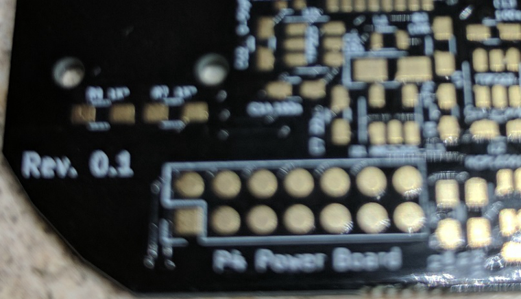
My boards came with the 14 pin connector as pads not through hole. Not sure how the hell I will solder a connector to that :-(
-
My boards came with the 14 pin connector as pads not through hole. Not sure how the hell I will solder a connector to that :-(
@shabba you can buy the 14 pins smd like this https://fr.aliexpress.com/item/100pcs-2x7-P-14-Pin-2-0-mm-Pin-Header-Female-Dual-row-SMT-PCB-surface/32729270520.html
;)
-
@shabba you can buy the 14 pins smd like this https://fr.aliexpress.com/item/100pcs-2x7-P-14-Pin-2-0-mm-Pin-Header-Female-Dual-row-SMT-PCB-surface/32729270520.html
;)
-
@tonnerre33 Thanks. I will try and source closer. After waiting a couple months for the parts I have it is frustrating to wait another few!
@shabba Did you try to desolder the connectors of the livolo top pcb ? If you can you will try without wait ;) I think you just need an hot air gun but i haven't test it.
In the future, could you tell me if you have some crash with the RFM69 because i have. But it's not the mtitiu's board, don't worry ;)
-
@shabba Did you try to desolder the connectors of the livolo top pcb ? If you can you will try without wait ;) I think you just need an hot air gun but i haven't test it.
In the future, could you tell me if you have some crash with the RFM69 because i have. But it's not the mtitiu's board, don't worry ;)
@tonnerre33 Wow! Never even thought of that! Doh! Will give that a go over next couple days. And for sure I will report how I get on with crashes etc.
-
How so? That's impossible. I used the elecrow pcb manufacturer and the boards are all fine with all the required holes. Where did you sent them for fabrication? Can you send some pictures?
-
That's very odd and not ok. I think their gerber software doesn't support the format that KiCAD generates. I didn't had any problems with other services I used so far - excepting PCBWay. But SeedStudio, Elecrow and even manufacturers from allpcb.com worked just fine. Yes, I use China mostly because it's waaay cheap than EU and the quality is very-very good for my needs.
And your current problem can't be fixed with smd header connectors as @tonnerre33 suggested because there are traces on both sides for the connector. I assume that those pads aren't connected through the board because there aren't any vias or something to pass through. So I think in the end you need to use a standart THT connector and before that you need to drill the board pads for the connector so that you can solder the connector on both sides. And it can be a little bit difficult.
Anyways you should issue a ticket to the pcbs.io service and tell them about this because it's not right at all...Their online gerber viewer doesn't render the connector holes at all and it even reports that the only drills present on the board are those under the touch pads only..
-
Oh it's true, i have forgotten there is 2 traces on the opposite side ... The 12V and the GND... I have never had a problem with pcbs.io, and i have ordered my livolo pcb with pcbs.io too !!
I like this seller because even if i did a mistake on my board they cancel my order if i ask it ;)
Did you test the Continuity between the bottom and the top of the 14 pins ?
Can you post the drill picture generated by pcbs.io like this :
or share the project and send the link