💬 RFM69 Livolo 2 channels 1 way EU switch(VL-C700X-1_Ver_C2)
-
My boards came with the 14 pin connector as pads not through hole. Not sure how the hell I will solder a connector to that :-(
-
My boards came with the 14 pin connector as pads not through hole. Not sure how the hell I will solder a connector to that :-(
@shabba you can buy the 14 pins smd like this https://fr.aliexpress.com/item/100pcs-2x7-P-14-Pin-2-0-mm-Pin-Header-Female-Dual-row-SMT-PCB-surface/32729270520.html
;)
-
@shabba you can buy the 14 pins smd like this https://fr.aliexpress.com/item/100pcs-2x7-P-14-Pin-2-0-mm-Pin-Header-Female-Dual-row-SMT-PCB-surface/32729270520.html
;)
-
@tonnerre33 Thanks. I will try and source closer. After waiting a couple months for the parts I have it is frustrating to wait another few!
@shabba Did you try to desolder the connectors of the livolo top pcb ? If you can you will try without wait ;) I think you just need an hot air gun but i haven't test it.
In the future, could you tell me if you have some crash with the RFM69 because i have. But it's not the mtitiu's board, don't worry ;)
-
@shabba Did you try to desolder the connectors of the livolo top pcb ? If you can you will try without wait ;) I think you just need an hot air gun but i haven't test it.
In the future, could you tell me if you have some crash with the RFM69 because i have. But it's not the mtitiu's board, don't worry ;)
@tonnerre33 Wow! Never even thought of that! Doh! Will give that a go over next couple days. And for sure I will report how I get on with crashes etc.
-
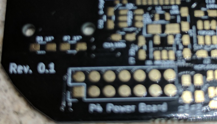
How so? That's impossible. I used the elecrow pcb manufacturer and the boards are all fine with all the required holes. Where did you sent them for fabrication? Can you send some pictures?
-
That's very odd and not ok. I think their gerber software doesn't support the format that KiCAD generates. I didn't had any problems with other services I used so far - excepting PCBWay. But SeedStudio, Elecrow and even manufacturers from allpcb.com worked just fine. Yes, I use China mostly because it's waaay cheap than EU and the quality is very-very good for my needs.
And your current problem can't be fixed with smd header connectors as @tonnerre33 suggested because there are traces on both sides for the connector. I assume that those pads aren't connected through the board because there aren't any vias or something to pass through. So I think in the end you need to use a standart THT connector and before that you need to drill the board pads for the connector so that you can solder the connector on both sides. And it can be a little bit difficult.
Anyways you should issue a ticket to the pcbs.io service and tell them about this because it's not right at all...Their online gerber viewer doesn't render the connector holes at all and it even reports that the only drills present on the board are those under the touch pads only..
-
Oh it's true, i have forgotten there is 2 traces on the opposite side ... The 12V and the GND... I have never had a problem with pcbs.io, and i have ordered my livolo pcb with pcbs.io too !!
I like this seller because even if i did a mistake on my board they cancel my order if i ask it ;)
Did you test the Continuity between the bottom and the top of the 14 pins ?
Can you post the drill picture generated by pcbs.io like this :
or share the project and send the link
-
Ok. I found the issue with pcbs.io service. They don't accept separate files for plated and non plated holes when it comes to gerber files. My default setting when generating gerbers from KiCAD is set to do that.
So here it's a set of gerbers for the boards(1 channel and 2 channel) with PTH and NPTH gerber files merged into one. If you upload these on pcbs.io you'll see that it renders correctly now. And it should be fabricated correctly too if their rendering page corresponds with the real product.- 1 channel variant:
0_1496990513816_livolo_1_channel_1way_eu_switch_rev0.1.zip - 2 channel variant:
0_1496990268774_livolo_2_channels_1way_eu_switch_rev0.1.zip
@shabba
Oh and the 1 channel board: please don't fabricate it yet because it may not fit from a mechanical point of view - the atmega328p is above the big mosfet from the power/relays board. So I have to see if everything fits there. But anyways don't be so impatient because both projects are marked as Work in progress on openhardware.io. I'm saying this because I don't want you or anyone else to waste money before the boards are tested for real. - 1 channel variant:
-
@mtiutiu Thanks - and I fully understand WIP. I am just trying to do the little I can by being a tester etc. I am also learning so very happy with that. I really appreciate all the effort you have done here.
-
This might be a good place to ask this :)
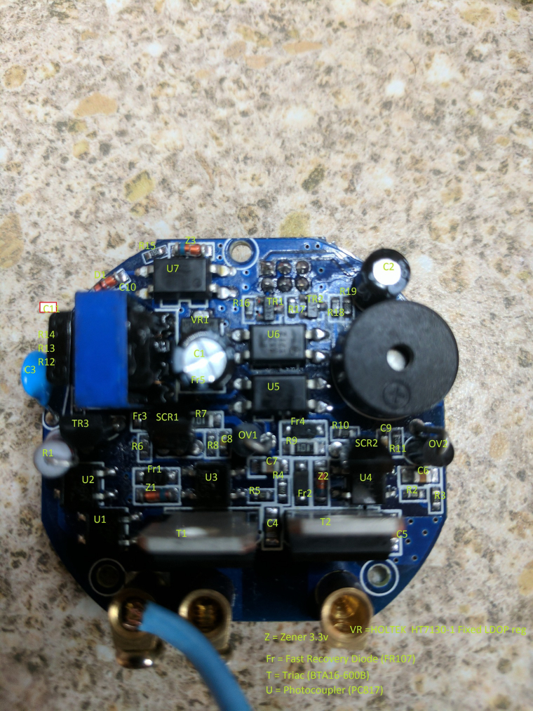
I bought a few types of switches like the Livolo. One of the generic brands is like this :+1:
https://goo.gl/photos/7tYxJfKFgwEGu4kX6
Does anyone know what the component on the left is with the blue stripe? I was guessing transformer. I have drawn out the schematics to see how I might hack in an arduino radio.
Attempt at drawing the circuit here :
https://easyeda.com/editor#id=933c96a537a446a29d272806876ab5a5I ma not sure if the diodes marked as zeners are actually zeners.
-
Shabba,
I can see, you was working three months ago in this project and you have some initial circuit draft. I know about this kind of devices and I can help you if you are still working on it.
We can split the circuit as following:
a. Power supply: TRANS1(You are right, it is high frequency transformer), high voltage transistor MJE13001 (Q1), optocoupler (U7) and some additional components.
b. Optocouplers interface: for signals from the control board: TR1/U2/BRG6, TR2/U3/BRG3 and some additional components.
c. Triacs (Power Circuits) : T1, T2.
Please let me know for working together.Thanks and best regards
-
@Lukaspp said in 💬 Livolo 2 channels 1 way EU switch(VL-C700X-1_Ver_C2):
transistor M
I would be delighted to help in any way but I would need direction. My electronics experience is pretty much limited to DC circuits.
@shabba A. Power Supply.
This is the standard circuit for a the power supply.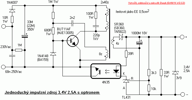
I redrawn your circuit trying to use the standard form and I can observe it can not provide enough current for both (Atmega328+ nFR24l01)**. So, I adjusted some components for getting 3.3V and 22ma. Atmega328-8Mhz + nFR24l01 Without LEd´s ~ 18ma/3V
**It is Worst for RFM69 which has more consume.
-
@shabba A. Power Supply.
This is the standard circuit for a the power supply.I redrawn your circuit trying to use the standard form and I can observe it can not provide enough current for both (Atmega328+ nFR24l01)**. So, I adjusted some components for getting 3.3V and 22ma. Atmega328-8Mhz + nFR24l01 Without LEd´s ~ 18ma/3V
**It is Worst for RFM69 which has more consume.
-
@Lukaspp said in 💬 Livolo 2 channels 1 way EU switch(VL-C700X-1_Ver_C2):
@Lukaspp : The Above pdf was tested with a simulation program but when I tested using real components I can not get the theoretical results. I had to ajust allmost to the original circuit from Shabba and the best power was 2.4V/13 ma. It is not enought for the couple Atmega328-8Mhz + NFR24l01. So, if the project friends want it is going further, the power Supply has to be out of this board. the rest of the board could be used. Opto Transistors TR1/TR2/ and Triacs. This is the final pdf for 2.4V/13ma.
-
Hello all,
I studied a little bit more this part of the circuit and it's a standard self oscillating flyback converter or a ringing choke converter as others call it. Indeed it provides the most compact solution for space constrained designs. But all of this comes at a cost: it's difficult to obtain a stable circuit and it has to be tuned by trial and error - at least this is what the literature says.
I'm not a switching power supplies expert here(even though I want to learn more about SMPS's in general but my time is limited for now) but I've come to a conclusion: it's difficult to tune this or to change the existing circuit to accommodate the mysensors circuits power requirements. I tried various combinations using sleep schemes and to change the flyback converter components as other mentioned in the mysensors forum and indeed I can power up my custom design that is presented in this thread BUT it's NOT STABLE. From time to time the switching transistor(mje13003) burns out and this is because I removed the resistor placed at the input of this power supply - near the bridge rectifier and replaced it with a wire(this is not the same resistor as @Lukaspp replaced from the base of the transistor which is the startup resistor for the flyback converter).
Now the only purpose that I imagine for this resistor is to suppress the transients - but it has a big value(100Kohm) which limits the current to a non-usable value for our purpose. I know that there are other solutions to overcome the transients but they are either bulky or too slow for this(correct me if I'm wrong here).
More than that let's not forget that we have 2 power supplies here and when the lights go on the first supply(flyback) input gets shorted by the relays contact(I have the relays variant btw not the one with triac) so I'm thinking that other transients appear here as the primary inductor doesn't like that as far as I know - so I assume the above mentioned resistor of 100Kohm comes into play here too. Another role for it would be to limit the inrush currents. I played with that value too but it needs to be very low to have something stable and I got a value around 200ohms but that doesn't help as it's too low and after some time the resistor burned up and saved my transistor :simple_smile: .
Now with all the tricks in the world and tuning the flyback converter to give more current this won't help as again let's not forget we have a SERIES circuit here so without external intervention we can't achieve that(only if we break somehow the laws of physics or maybe my thinking is limited :simple_smile: ). In this case the external capacitor placed across the light bulb comes into play to supply enough current to the standby circuit which is our flyback converter over here. I played with that one too and from 0,47uF I got to 4.7uF to have a decent result - but this one gets bulky and more expensive from obvious reasons. And let's not forget that the light bulb itself has some impact overall because this is the actual LOAD that we want to control and there are various light bulbs over there with various requirements. More than that they have their power supply embedded which in most of the cases is a(you guessed maybe): a self oscillating FLYBACK CONVERTER or similar. So this one too has inrush currents, transients which are sensed down the line to our dear Livolo switch and affects my custom board stability again :simple_smile: - isn't life beautiful? :simple_smile:
So far these are the results of my trials and none of them proved to be stable so I kinda gave up on this and will try to use a normal powering scheme somehow(as Sonoff switches with a battery powered touch switch on the wall). Not the best solution of all but this is what you get when the infrastructure wasn't thought for this scenarios from the beginning.
The Livolo guys thought of all of this I assume so that's why they stayed only with a simple circuit - a PIC mcu which maybe sleeps most of the time and a simple radio receiver which draws around 5mA or even less - so yeah that's why this works and it's stable in its original form.