nRF5 Multi Sensor Board (12-14€)
-
I don't know if you already managed to read correctly the BLE data.
Here follows what I get from this (nice and cheap!) sensor. Any tip about decoding?0x6E400002 ACCELEROMETER (Acceleration)
0xFFA0002A3628 (it seems FA00 for x, 02A3 for y , 3628 for z)0x6E400003 GYROSCOPE (Angular velocity)
0xFFA7007FFFC4SERVICE 0x6E400004 BAROMETER (Pressure)
0x0018BE9 (on the table)
0x0018BDD (about 50 cm above the table)SERVICE 0x6E400005 TEMPERATURE
0x012E (ambient)
0x0140 (inside warm hand)SERVICE 0x6E400006 AMBIENT LIGHT
0x0000 (dark)
0x0936 (direct LED torch) -
As usual, ask for something on a public forum and ~5 minutes later, I finally find it myself:
http://linksprite.com/wiki/index.php5?title=Bluetooth_4.0_BLE_Sensor_Tag/iBeacon_Station_NRF51822
-
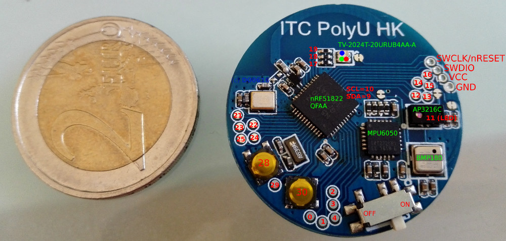
The "ITC PolyU HK" is one of the most interesting nRF5 Boards I have found. This board is useable with the upcoming MySensors 2.2 release. The radio can communicate with nRF24 networks.
At eBay or aliexpress boards are available starting at 12€. The ob board hardware is:
- nRF51822QFAA (Cortex-M0, 16kB RAM, 256kb Flash, SPI, I2C, UART...)
- Two Buttons
- one RGB LED
- MPU6050 accelerometer
- AP3216C distance and ambient light sensor
- BMP180 pressure and temperature sensor
- CR2032 Battery Holder
At the moment I have decoded the layout. There is no arduino-nrf5 board definition. My idea is to build a repository of YAML based board definitions to generate board definitions without letting the list of arduino-nrf5 included boards growing.
Issues:
- Board is not supported by arduino-nrf5 at the moment
- UART only available via two of the solder/contact pads
- ~~Sleeping until pin interrupt consumes 1mA -> https://github.com/sandeepmistry/arduino-nRF5/issues/153~~
When the arduino-nrf5 board definition is ready, I reply here.
@d00616 said in nRF5 Multi Sensor Board (12-14€):
Sleeping until pin interrupt consumes 1mA -> https://github.com/sandeepmistry/arduino-nRF5/issues/153
I have found some documentation. The high current consumption was listed as PAN#39 and is fixed with this MCU: http://infocenter.nordicsemi.com/pdf/nRF51822-pan_v3.0.pdf
The MCU is nRF51822QFAAH0.
-
@d00616 said in nRF5 Multi Sensor Board (12-14€):
Sleeping until pin interrupt consumes 1mA -> https://github.com/sandeepmistry/arduino-nRF5/issues/153
I have found some documentation. The high current consumption was listed as PAN#39 and is fixed with this MCU: http://infocenter.nordicsemi.com/pdf/nRF51822-pan_v3.0.pdf
The MCU is nRF51822QFAAH0.
@d00616 said in nRF5 Multi Sensor Board (12-14€):
@d00616 said in nRF5 Multi Sensor Board (12-14€):
Sleeping until pin interrupt consumes 1mA -> https://github.com/sandeepmistry/arduino-nRF5/issues/153
I have found some documentation. The high current consumption was listed as PAN#39 and is fixed with this MCU: http://infocenter.nordicsemi.com/pdf/nRF51822-pan_v3.0.pdf
The MCU is nRF51822QFAAH0.
I don't see the link with anomaly #39 ?
But I see it #72 which is not fixed72. RTC: Writing to RTC registers without starting the LFCLK could lead to increased current consumption.
Symptoms:
Increased current consumption
.
Conditions:
Setting up the RTC by writing to its registers without starting the LFCLK
.
Consequences:
The user will experience an increase in the current consumption of ~1 mA
.
Workaround:
Always run the LFCLK for a minimum of one LFCLK clock cycle after writing to the RTC registers. -
@Nca78
I think it was about the GPIOTE module and pin interrupts needing hfclk, so more power, #39, p.4, listed as fixedThank you @scalz I took time for some reading about NRF51 (should have done that before posting stupid things... :blush: ) and it's much clearer now...
My one and only NRF51822 has build code H0 so it seems I will not pull too many hair when trying to make it run at low power :)
-
@MiKa Here is my sketch if it helps (MySensors v2.2.0-Beta). It uses ALS, BMP180 and RGB leds.
Working well with my nRF24 LNA+PA GW.#include <Arduino.h> #define MY_DEBUG #define MY_BAUD_RATE 9600 // Mode Radio / Enable and select radio type attached #define MY_RADIO_NRF5_ESB #define MY_NRF5_ESB_PA_LEVEL NRF5_PA_MAX #define MY_NODE_ID 6 #include "MySensors.h" #include <Wire.h> #include <Adafruit_BMP085.h> Adafruit_BMP085 bmp = Adafruit_BMP085(); #define CHILD_ID_TEMP 0 #define CHILD_ID_BARO 1 #define CHILD_ID_ALS 2 #define SLEEP_NODE true // True to activate Sleep Mode, but currently unsupported on esp8266 unsigned long SLEEP_TIME = 120 * 1000; // Sleep time between reads (in milliseconds) #define RED_PIN 17 #define GREEN_PIN 18 #define BLUE_PIN 19 #define COLOR_OFF 0 #define COLOR_RED 1 #define COLOR_GREEN 2 #define COLOR_BLUE 4 MyMessage msgTemp(CHILD_ID_TEMP, V_TEMP); MyMessage msgBaro(CHILD_ID_BARO, V_PRESSURE); MyMessage msgForecast(CHILD_ID_BARO, V_FORECAST); MyMessage msgALS(CHILD_ID_ALS, V_LIGHT_LEVEL); void setColor (uint8_t c) { digitalWrite (RED_PIN, !(c & COLOR_RED)); digitalWrite (GREEN_PIN, !(c & COLOR_GREEN)); digitalWrite (BLUE_PIN, !(c & COLOR_BLUE)); } void setup() { setColor (COLOR_RED); setColor (COLOR_GREEN); setColor (COLOR_BLUE); Wire.begin(); pinMode (RED_PIN, OUTPUT); pinMode (GREEN_PIN, OUTPUT); pinMode (BLUE_PIN, OUTPUT); setColor (COLOR_RED); delay(250); setColor (COLOR_GREEN); delay(250); setColor (COLOR_BLUE); delay(250); setColor (COLOR_OFF); /* BMP180. */ if (!bmp.begin()) { Serial.println("Could not find a valid BMP085 sensor, check wiring!"); setColor (COLOR_RED); while (1); } } void presentation() { sendSketchInfo("nrf Sensor TAG", "1.0.0"); // Sensor presentation to the GW present(CHILD_ID_TEMP, S_TEMP); present(CHILD_ID_BARO, S_BARO); present(CHILD_ID_ALS, S_LIGHT_LEVEL); } void AP3216_write(uint8_t regAddress, uint8_t value) { Wire.beginTransmission(0x1E); // I2C Address of AP3216 sensor is 0x1E Wire.write(regAddress); Wire.write(value); Wire.endTransmission(); } uint8_t AP3216_read(uint8_t regAddress) { Wire.beginTransmission(0x1E); // I2C Address of AP3216 sensor is 0x1E Wire.write(regAddress); Wire.endTransmission(); Wire.requestFrom(0x1E, 1, true); return Wire.read() & 0xFF; } uint16_t readALS (void) { /* System mode: ALS function once */ AP3216_write (0x0, 0x5); delay (250); return ((uint16_t) AP3216_read (0xC) << 8) | AP3216_read (0xD); } void loop() { send(msgTemp.set(bmp.readTemperature(), 1)); send(msgBaro.set(bmp.readPressure(), 1)); send(msgForecast.set(bmp.readSealevelPressure(834.0), 1)); /* Change altitude here ! */ send(msgALS.set(readALS(), 1)); setColor (COLOR_BLUE); delay (250); setColor (COLOR_OFF); if (SLEEP_NODE) sleep(SLEEP_TIME); else delay (SLEEP_TIME); }You also need to change SDA/SCL pins by creating a new board from the Generic nRF51 (or modifying it)
In variant.h:#define PIN_WIRE_SDA (9u) #define PIN_WIRE_SCL (10u) -
@MiKa Here is my sketch if it helps (MySensors v2.2.0-Beta). It uses ALS, BMP180 and RGB leds.
Working well with my nRF24 LNA+PA GW.#include <Arduino.h> #define MY_DEBUG #define MY_BAUD_RATE 9600 // Mode Radio / Enable and select radio type attached #define MY_RADIO_NRF5_ESB #define MY_NRF5_ESB_PA_LEVEL NRF5_PA_MAX #define MY_NODE_ID 6 #include "MySensors.h" #include <Wire.h> #include <Adafruit_BMP085.h> Adafruit_BMP085 bmp = Adafruit_BMP085(); #define CHILD_ID_TEMP 0 #define CHILD_ID_BARO 1 #define CHILD_ID_ALS 2 #define SLEEP_NODE true // True to activate Sleep Mode, but currently unsupported on esp8266 unsigned long SLEEP_TIME = 120 * 1000; // Sleep time between reads (in milliseconds) #define RED_PIN 17 #define GREEN_PIN 18 #define BLUE_PIN 19 #define COLOR_OFF 0 #define COLOR_RED 1 #define COLOR_GREEN 2 #define COLOR_BLUE 4 MyMessage msgTemp(CHILD_ID_TEMP, V_TEMP); MyMessage msgBaro(CHILD_ID_BARO, V_PRESSURE); MyMessage msgForecast(CHILD_ID_BARO, V_FORECAST); MyMessage msgALS(CHILD_ID_ALS, V_LIGHT_LEVEL); void setColor (uint8_t c) { digitalWrite (RED_PIN, !(c & COLOR_RED)); digitalWrite (GREEN_PIN, !(c & COLOR_GREEN)); digitalWrite (BLUE_PIN, !(c & COLOR_BLUE)); } void setup() { setColor (COLOR_RED); setColor (COLOR_GREEN); setColor (COLOR_BLUE); Wire.begin(); pinMode (RED_PIN, OUTPUT); pinMode (GREEN_PIN, OUTPUT); pinMode (BLUE_PIN, OUTPUT); setColor (COLOR_RED); delay(250); setColor (COLOR_GREEN); delay(250); setColor (COLOR_BLUE); delay(250); setColor (COLOR_OFF); /* BMP180. */ if (!bmp.begin()) { Serial.println("Could not find a valid BMP085 sensor, check wiring!"); setColor (COLOR_RED); while (1); } } void presentation() { sendSketchInfo("nrf Sensor TAG", "1.0.0"); // Sensor presentation to the GW present(CHILD_ID_TEMP, S_TEMP); present(CHILD_ID_BARO, S_BARO); present(CHILD_ID_ALS, S_LIGHT_LEVEL); } void AP3216_write(uint8_t regAddress, uint8_t value) { Wire.beginTransmission(0x1E); // I2C Address of AP3216 sensor is 0x1E Wire.write(regAddress); Wire.write(value); Wire.endTransmission(); } uint8_t AP3216_read(uint8_t regAddress) { Wire.beginTransmission(0x1E); // I2C Address of AP3216 sensor is 0x1E Wire.write(regAddress); Wire.endTransmission(); Wire.requestFrom(0x1E, 1, true); return Wire.read() & 0xFF; } uint16_t readALS (void) { /* System mode: ALS function once */ AP3216_write (0x0, 0x5); delay (250); return ((uint16_t) AP3216_read (0xC) << 8) | AP3216_read (0xD); } void loop() { send(msgTemp.set(bmp.readTemperature(), 1)); send(msgBaro.set(bmp.readPressure(), 1)); send(msgForecast.set(bmp.readSealevelPressure(834.0), 1)); /* Change altitude here ! */ send(msgALS.set(readALS(), 1)); setColor (COLOR_BLUE); delay (250); setColor (COLOR_OFF); if (SLEEP_NODE) sleep(SLEEP_TIME); else delay (SLEEP_TIME); }You also need to change SDA/SCL pins by creating a new board from the Generic nRF51 (or modifying it)
In variant.h:#define PIN_WIRE_SDA (9u) #define PIN_WIRE_SCL (10u)@Ptibu said in nRF5 Multi Sensor Board (12-14€):
@MiKa Here is my sketch if it helps. It uses ALS, BMP180 and RGB leds.
Working well with my nRF24 LNA+PA GW.Thank you sharing your sketch. You can use https://github.com/mysensors/ArduinoHwNRF5 to redefine pin mappings in your sketch.
-
@Ptibu said in nRF5 Multi Sensor Board (12-14€):
@MiKa Here is my sketch if it helps. It uses ALS, BMP180 and RGB leds.
Working well with my nRF24 LNA+PA GW.Thank you sharing your sketch. You can use https://github.com/mysensors/ArduinoHwNRF5 to redefine pin mappings in your sketch.
-
Hi,
Thanks for sketch, I will try
Which interface You use for upload?
I tryied ST-Link V2 from ebay it seems it working but I cant get working J-link under arduino (J-link also small version from Ali)
https://www.aliexpress.com/item/Die-Jlink-OB-ARM-emulator-debugger-jlink-programmierer-downloader-link-statt-V8-SWD/32763735160.html?spm=a2g0s.9042311.0.0.VVtIj7
Regards,
MiKa -
I don't know if you already managed to read correctly the BLE data.
Here follows what I get from this (nice and cheap!) sensor. Any tip about decoding?0x6E400002 ACCELEROMETER (Acceleration)
0xFFA0002A3628 (it seems FA00 for x, 02A3 for y , 3628 for z)0x6E400003 GYROSCOPE (Angular velocity)
0xFFA7007FFFC4SERVICE 0x6E400004 BAROMETER (Pressure)
0x0018BE9 (on the table)
0x0018BDD (about 50 cm above the table)SERVICE 0x6E400005 TEMPERATURE
0x012E (ambient)
0x0140 (inside warm hand)SERVICE 0x6E400006 AMBIENT LIGHT
0x0000 (dark)
0x0936 (direct LED torch) -
The "ITC PolyU HK" is one of the most interesting nRF5 Boards I have found. This board is useable with the upcoming MySensors 2.2 release. The radio can communicate with nRF24 networks.
At eBay or aliexpress boards are available starting at 12€. The ob board hardware is:
- nRF51822QFAA (Cortex-M0, 16kB RAM, 256kb Flash, SPI, I2C, UART...)
- Two Buttons
- one RGB LED
- MPU6050 accelerometer
- AP3216C distance and ambient light sensor
- BMP180 pressure and temperature sensor
- CR2032 Battery Holder
At the moment I have decoded the layout. There is no arduino-nrf5 board definition. My idea is to build a repository of YAML based board definitions to generate board definitions without letting the list of arduino-nrf5 included boards growing.
Issues:
- Board is not supported by arduino-nrf5 at the moment
- UART only available via two of the solder/contact pads
- ~~Sleeping until pin interrupt consumes 1mA -> https://github.com/sandeepmistry/arduino-nRF5/issues/153~~
When the arduino-nrf5 board definition is ready, I reply here.
@d00616 really wonderful of you to do the pinout work you have done, thank-you.
I have got the accelerometer (MPU6050) working as a service in nordic mbed, and I thought I would throw in some of what I learned to add to the great work you have done.
The schematic shows that the AD0 (pin 9) is floating (it is not, thank heavens!) it is tied to the VLogic pin ( pin 8 ). This results in the 7-Bit address of the board changing from 0x68 to 0x69.
I hope this helps others.
Also, other I2C also as posted by @Ptibu
Bosch BMP180 is 0x77 - untested
The AP3216C is 0x1E - untested
MPU6050 is 0x69 - works - testedAlso pins 17,18,19 are Red Green Blue
(And not Red Blue Green as shown on the schematic)thanks for your help.
bb
-
Hi Guys
Sorry for bringing the level of that thread down...
This little thing looks wonderful... but :
Could it be a direct replacement of Arduino Pro Mini and nRF24L01+ ?
Thanks a lot gentlemen !
@ben999 said in nRF5 Multi Sensor Board (12-14€):
Could it be a direct replacement of Arduino Pro Mini and nRF24L01+ ?
Maybe, the NRF5 can replace the combination of ATMEGA+NRF24 chips but it's a 3.3V chip and I don't know an NRF5 board in Arduino Pro Mini layout.
Please look at https://forum.mysensors.org/topic/6961/nrf5-bluetooth-action/1092 for pros and cons.
At the moment the radio protocol is a little bit unstable, because there is an hardware issue, which must be fixed in software. At the moment I do a rewrite of the ESB protocol, which fix this issue. My old implementation is hard to debug. With my new implementation the radio states are separated into extra functions and I use more of the nice event driven capabilities (PPI, Shorts). Until I have finished this fix, sometimes an NRF52 needs an reset.
-
@d00616 said in nRF5 Multi Sensor Board (12-14€):
Sleeping until pin interrupt consumes 1mA -> https://github.com/sandeepmistry/arduino-nRF5/issues/153
I have found some documentation. The high current consumption was listed as PAN#39 and is fixed with this MCU: http://infocenter.nordicsemi.com/pdf/nRF51822-pan_v3.0.pdf
The MCU is nRF51822QFAAH0.
@d00616 said in nRF5 Multi Sensor Board (12-14€):
@d00616 said in nRF5 Multi Sensor Board (12-14€):
Sleeping until pin interrupt consumes 1mA -> https://github.com/sandeepmistry/arduino-nRF5/issues/153
I have found some documentation. The high current consumption was listed as PAN#39 and is fixed with this MCU: http://infocenter.nordicsemi.com/pdf/nRF51822-pan_v3.0.pdf
The MCU is nRF51822QFAAH0.
I don't know how the sleep is implemented (CONFIG/GPIOTE) and if I'm facing this bug, but my battery lasts 2 days, with a wake-up period of 2 minutes (QFAAH0 MCU)... any idea?