nRF5 action!
-
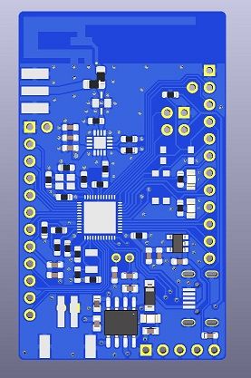
I just gave this design to pcb fab and cant wait to test it out. I made and tested a similar board using nrf52840 but soldering aQFN package is a nightmare and i needed to cancel quite abit of pins to increase the success chance.
So this design is based on nrf52832with a normal QFN package which is easy to solder and that allowed me to breakout every single pin (except P0.07). Can be powered with a single cell lipo or USB port and managed to fit in a charger for it with a charging indicator led. It has a voltage divider to measure the battery but it can be desoldered if the pin is needed for another function.
Comes with PA and LNA just like my nrf52840 test and had to follow quite abit of design recommendations from the datasheet.
Some pins are compatible with adafruit 52832 circuit design just in case if i want to use their bootloader. Like reset, DFU, 2 different leds are connected to the same pins as in their board design. Also theres a selector 0 ohm resistor between pcb and external antenna.
I will report when i receive and test it!
-
@acb I have a couple of Ebyte's E73 modules. I also have BMP, so it shouldn't be a problem.
If you could share your bootloader for 52840 it would be a great start for my tinkering.@acb said in nRF5 action!:
I couldn't get Nordic's default Dongle bootloader to play nicely with MySensors (at the time).
So have you gotten any success eventually?
Once again, thank you for such extensive information :) I hope others will appreciate it too.@monte, @NeverDie - Took some time this weekend to take a look at this and used my previous post as something of a template; hope it helps...
Re: Nordic’s default Dongle bootloader - I never managed to get it to play nicely with MySensors and so abandoned it completely in favor of a modified version of Adafruit’s again, since I was already familiar with it from my nRF52832 work. It would have been nice if Nordic had revealed their private key to move/replace their bootloader, but I get it, I figure they’d rather you bought their DK.
This is the custom bootloader (.HEX file) my Nordic nRF52840 Dongle nodes currently use. You’ll need to completely wipe any current Dongle (or EByte E73 module) using a JLink/BMP before flashing. It has the following MySensors-compatible regions either “in-mind” or in-place:
0x00000 to 0x00FFF - 4K MBR Region, currently up to 0xAFF.
0x01000 to 0x25FFF - 148K SoftDevice Region, currently with S140 up to 0x25DE7.
0x26000 to 0xEFFFF - 807K Application Region, bootloader will intelligently fill.
0xF0000 to 0xF0FFF - 4K VirtualPage? managed by arduino-NVM.
0xF4000 to 0xFD7FF - 38K Bootloader Region, currently custom up to 0xFC01F.
0xFD800 to 0xFDFFF - 2K Bootloader Config, currently custom up to 0xFD857, 88B.
0xFF000 to 0xFFFFF - 4K “EEPROM” Area? managed by arduino-NVM.The linked bootloader will of course expect the same pin connections as the Dongle. The important ones are probably only:
LED1_YLW_GREEN on P0.06

LED2_RGB_RED   on P0.08
LED2_RGB_GREEN on P1.09
LED2_RGB_BLUE  on P0.12

USR BTN on P1.06
BLE DFU on P1.10

MCU RST on P0.21
The bootloader supports CDC, DFU and UF2 upload modes. So the first time you flash the bootloader and reset, you can then mount it as a removable drive with UF2 support for drag-and-drop uploading of applications and/or new bootloader images, etc.
It should also appear as a usual COM port via it’s CDC descriptors, enabling FTDI-like uploading through PlatformIO/Arduino IDEs. And as before, you can perform DFUs over BLE through a manual combination button-press - more on that below...
Also as before, the bootloader shows the upload state through the LEDs, but note that on the Dongle, the LEDs are all active LOW - i.e. drive a logic zero (‘0’) to illuminate the LED(s). If you’d like a version of the bootloader where the LEDs are all active HIGH, let me know and I’ll try to dig out my old environment and compile something - you can do this yourself though… ;)
Manually entering these upload states is similar to the nRF52832. Uploading via FTDI works as you would expect. Ground P1.06 (USR BTN) and reset (ground P0.21, MCU RST, briefly) and the nRF52840 will expect a DFU over USB either via it’s COM port or UF2 if mounted. On the Dongle, LED1 will fade up and down slowly and I think the RGB LED goes green if mounted.
For DFUs over BLE, ground P1.06 (USR BTN) and P1.10 and reset. I chose P1.10 because it’s right next to a ground pin on the Dongle and I just soldered another push switch to it. LED1 fades up and down more quickly together with the RGB LED turning blue to confirm. Uploading is via Nordic’s nRF Toolbox app and again, if you’re using Adafruit’s BSP you’ll get the built-in enterSerialDfu() and enterOTADfu() sketch functions to perform the same button operations as above.
As far as prepping MySensors goes, the same applies as above with the nRF52832, only this time you’ll need to up the data rate to 1Mbps or higher, as I mentioned earlier.
I could upload Arduino IDE and PlatformIO board variants for the Dongle if you’d like. But it’s straightforward enough to create variants for your specific board. If you’re using the Dongle, probably the most useful thing I have to hand is this code-snippet for enabling the regulator:
// Set REGOUT0 to 3V mode
// https://devzone.nordicsemi.com/nordic/short-range-guides/b/getting-started/posts/nrf52840-dongle-programming-tutorial
if ((NRF_UICR->REGOUT0 & UICR_REGOUT0_VOUT_Msk) ==
    (UICR_REGOUT0_VOUT_DEFAULT << UICR_REGOUT0_VOUT_Pos))
{
    NRF_NVMC->CONFIG = NVMC_CONFIG_WEN_Wen;
    while (NRF_NVMC->READY == NVMC_READY_READY_Busy);

    NRF_UICR->REGOUT0 = (NRF_UICR->REGOUT0 & ~((uint32_t)UICR_REGOUT0_VOUT_Msk)) |
                        (UICR_REGOUT0_VOUT_3V0 << UICR_REGOUT0_VOUT_Pos);

    NRF_NVMC->CONFIG = NVMC_CONFIG_WEN_Ren;
    while (NRF_NVMC->READY == NVMC_READY_READY_Busy);

    // System reset is needed to update UICR registers.
    NVIC_SystemReset();
}
If you stick this in an initVariant function in your variants.cpp, the Adafruit nRF52 BSP will call it as part of main.
I think that's everything - I hope it was helpful - any questions, I’ll do my best to respond a bit faster this time!
Famous last words... ;)
-
@monte, @NeverDie - Took some time this weekend to take a look at this and used my previous post as something of a template; hope it helps...
Re: Nordic’s default Dongle bootloader - I never managed to get it to play nicely with MySensors and so abandoned it completely in favor of a modified version of Adafruit’s again, since I was already familiar with it from my nRF52832 work. It would have been nice if Nordic had revealed their private key to move/replace their bootloader, but I get it, I figure they’d rather you bought their DK.
This is the custom bootloader (.HEX file) my Nordic nRF52840 Dongle nodes currently use. You’ll need to completely wipe any current Dongle (or EByte E73 module) using a JLink/BMP before flashing. It has the following MySensors-compatible regions either “in-mind” or in-place:
0x00000 to 0x00FFF - 4K MBR Region, currently up to 0xAFF.
0x01000 to 0x25FFF - 148K SoftDevice Region, currently with S140 up to 0x25DE7.
0x26000 to 0xEFFFF - 807K Application Region, bootloader will intelligently fill.
0xF0000 to 0xF0FFF - 4K VirtualPage? managed by arduino-NVM.
0xF4000 to 0xFD7FF - 38K Bootloader Region, currently custom up to 0xFC01F.
0xFD800 to 0xFDFFF - 2K Bootloader Config, currently custom up to 0xFD857, 88B.
0xFF000 to 0xFFFFF - 4K “EEPROM” Area? managed by arduino-NVM.The linked bootloader will of course expect the same pin connections as the Dongle. The important ones are probably only:
LED1_YLW_GREEN on P0.06

LED2_RGB_RED   on P0.08
LED2_RGB_GREEN on P1.09
LED2_RGB_BLUE  on P0.12

USR BTN on P1.06
BLE DFU on P1.10

MCU RST on P0.21
The bootloader supports CDC, DFU and UF2 upload modes. So the first time you flash the bootloader and reset, you can then mount it as a removable drive with UF2 support for drag-and-drop uploading of applications and/or new bootloader images, etc.
It should also appear as a usual COM port via it’s CDC descriptors, enabling FTDI-like uploading through PlatformIO/Arduino IDEs. And as before, you can perform DFUs over BLE through a manual combination button-press - more on that below...
Also as before, the bootloader shows the upload state through the LEDs, but note that on the Dongle, the LEDs are all active LOW - i.e. drive a logic zero (‘0’) to illuminate the LED(s). If you’d like a version of the bootloader where the LEDs are all active HIGH, let me know and I’ll try to dig out my old environment and compile something - you can do this yourself though… ;)
Manually entering these upload states is similar to the nRF52832. Uploading via FTDI works as you would expect. Ground P1.06 (USR BTN) and reset (ground P0.21, MCU RST, briefly) and the nRF52840 will expect a DFU over USB either via it’s COM port or UF2 if mounted. On the Dongle, LED1 will fade up and down slowly and I think the RGB LED goes green if mounted.
For DFUs over BLE, ground P1.06 (USR BTN) and P1.10 and reset. I chose P1.10 because it’s right next to a ground pin on the Dongle and I just soldered another push switch to it. LED1 fades up and down more quickly together with the RGB LED turning blue to confirm. Uploading is via Nordic’s nRF Toolbox app and again, if you’re using Adafruit’s BSP you’ll get the built-in enterSerialDfu() and enterOTADfu() sketch functions to perform the same button operations as above.
As far as prepping MySensors goes, the same applies as above with the nRF52832, only this time you’ll need to up the data rate to 1Mbps or higher, as I mentioned earlier.
I could upload Arduino IDE and PlatformIO board variants for the Dongle if you’d like. But it’s straightforward enough to create variants for your specific board. If you’re using the Dongle, probably the most useful thing I have to hand is this code-snippet for enabling the regulator:
// Set REGOUT0 to 3V mode
// https://devzone.nordicsemi.com/nordic/short-range-guides/b/getting-started/posts/nrf52840-dongle-programming-tutorial
if ((NRF_UICR->REGOUT0 & UICR_REGOUT0_VOUT_Msk) ==
    (UICR_REGOUT0_VOUT_DEFAULT << UICR_REGOUT0_VOUT_Pos))
{
    NRF_NVMC->CONFIG = NVMC_CONFIG_WEN_Wen;
    while (NRF_NVMC->READY == NVMC_READY_READY_Busy);

    NRF_UICR->REGOUT0 = (NRF_UICR->REGOUT0 & ~((uint32_t)UICR_REGOUT0_VOUT_Msk)) |
                        (UICR_REGOUT0_VOUT_3V0 << UICR_REGOUT0_VOUT_Pos);

    NRF_NVMC->CONFIG = NVMC_CONFIG_WEN_Ren;
    while (NRF_NVMC->READY == NVMC_READY_READY_Busy);

    // System reset is needed to update UICR registers.
    NVIC_SystemReset();
}
If you stick this in an initVariant function in your variants.cpp, the Adafruit nRF52 BSP will call it as part of main.
I think that's everything - I hope it was helpful - any questions, I’ll do my best to respond a bit faster this time!
Famous last words... ;)
@acb Thanks for your post!
My nRF52 skills have gotten a bit rusty, so in case you're no longer around when I circle back to this toopic in the future, I'm going to jump the gun and ask you now so that your answer can be memorialized here and then suitably curated by Hek for years to come: How exactly do you ensure that your bootloader is loaded into the proper bootloader memory segments and not treated like a regular program and stored in ordinary, non-privlidged program memory? I'm guessing it's accomplished through a linker directive of some kind? If you could share even a brief simple example here on how to implant the bootloader code where it needs to be, I'm sure it would be immensely helpful to anyone who wants to create a custom bootloader of their own. ;-)
Actually, it seems you did offer a summary of how to do it when you wrote "Manually entering these upload states is similar to the nRF52832. Uploading via FTDI works as you would expect. Ground P1.06 (USR BTN) and reset (ground P0.21, MCU RST, briefly) and the nRF52840 will expect a DFU over USB either via it’s COM port or UF2 if mounted. On the Dongle, LED1 will fade up and down slowly and I think the RGB LED goes green if mounted.", but again a step-by-step actual example, with demo files, would really drive it home. Now, some people might consider that much detail would constitute a "no thinking required" guide and therefore overkill, but I'd prefer overkill to underkill any day. I'm sure at least some others who are reading this would rather have s complete demo example that's too basic than have to puzzle over a missing or vague step. It may not seem like it's missing or vague to you now, but believe me if you ever have to switch to a different project for a while, it might not look anywhere near as obvious or as familiar when you come back to pick up where you left off.
So, if I can prevail upon you to put together even a very simple demo, I'd volunteer right away as a test subject to see if I could replicate it. And if I can, then you can be confident that if you had to shelf your work then you could come back years later and resume without help just based upon re-reading your own notes. :sunglasses:
-
@acb Thanks for your post!
My nRF52 skills have gotten a bit rusty, so in case you're no longer around when I circle back to this toopic in the future, I'm going to jump the gun and ask you now so that your answer can be memorialized here and then suitably curated by Hek for years to come: How exactly do you ensure that your bootloader is loaded into the proper bootloader memory segments and not treated like a regular program and stored in ordinary, non-privlidged program memory? I'm guessing it's accomplished through a linker directive of some kind? If you could share even a brief simple example here on how to implant the bootloader code where it needs to be, I'm sure it would be immensely helpful to anyone who wants to create a custom bootloader of their own. ;-)
Actually, it seems you did offer a summary of how to do it when you wrote "Manually entering these upload states is similar to the nRF52832. Uploading via FTDI works as you would expect. Ground P1.06 (USR BTN) and reset (ground P0.21, MCU RST, briefly) and the nRF52840 will expect a DFU over USB either via it’s COM port or UF2 if mounted. On the Dongle, LED1 will fade up and down slowly and I think the RGB LED goes green if mounted.", but again a step-by-step actual example, with demo files, would really drive it home. Now, some people might consider that much detail would constitute a "no thinking required" guide and therefore overkill, but I'd prefer overkill to underkill any day. I'm sure at least some others who are reading this would rather have s complete demo example that's too basic than have to puzzle over a missing or vague step. It may not seem like it's missing or vague to you now, but believe me if you ever have to switch to a different project for a while, it might not look anywhere near as obvious or as familiar when you come back to pick up where you left off.
So, if I can prevail upon you to put together even a very simple demo, I'd volunteer right away as a test subject to see if I could replicate it. And if I can, then you can be confident that if you had to shelf your work then you could come back years later and resume without help just based upon re-reading your own notes. :sunglasses:
Thanks @NeverDie, I appreciate that.
Okay, well, the short answer to your question is yes, it’s a “linker directive” or rather a series of them, usually a file with the .ld extension. There’s normally a general stack/heap/etc. one called nrf_common.ld in Adafruit’s BSP, and then an architecture-specific one: nrf52.ld I think for the nRF52832 and nrf52840.ld for, well, I bet you can guess! ;)
This architecture-specific linker directive contains the memory locations for things like the MBR, ram region for the bootloader, initialized and (shared) non-init RAM, bootloader settings/configuration, MBR parameters, etc. The bootloader itself can of course read this memory allocation/settings/configuration data and then load any new application code or indeed new bootloader code wherever it needs to be. That’s why it’s best to let the bootloader perform the FOTA, either via serial or BLE.
Now I’m guessing here, but ideally, the arduino-NVM library that sort of emulates AVR EEPROM for MySensors could just read this information too and store it’s virtual EEPROM pages around these allocations. Currently, I think it just tries to determine the top application page address from the UICR and then allocate the pages based on that. It’s been a while since I looked at the code, so it might have changed. Essentially, it’s trying to find where the bootloader starts (if there is one) and allocate some pages a bit back from there to be safe.
In theory, a large enough application could overwrite this area - that’s why it’s not the best solution as I mentioned earlier - but if you reach that point, you’ve gotten so close to the bootloader with your application code, you might be in (other) trouble anyway! ;)
As far as a step-by-step with actual example code, demo files, etc. I’m more than happy to do it but it’ll take me some time. And would be helped if you could specify a particular board you’d like me to target (especially if I have one lying around), e.g. Nordic’s nRF52840 Dongle, Ebyte module, etc?
The other side of this is the FreeRTOS side. Would you like examples for the lowest possible power?
It seems like that’s how folk like these devices to operate. Going down around 2µA in bare System ON sleep (nRF52832) and around 300nA in bare System OFF sleep requires more involved MySensors code modifications, due to (among other things!) how FreeRTOS takes care of the power management when idling, use of the RTC(s), how it handles ISR callbacks, attaches interrupts, etc. By “bare” I mean no additional sensors, just, for example, a button or internal RTC (only in System ON) to wake it.
Does all, or at least some, of that make sense? :)
-
Thanks @NeverDie, I appreciate that.
Okay, well, the short answer to your question is yes, it’s a “linker directive” or rather a series of them, usually a file with the .ld extension. There’s normally a general stack/heap/etc. one called nrf_common.ld in Adafruit’s BSP, and then an architecture-specific one: nrf52.ld I think for the nRF52832 and nrf52840.ld for, well, I bet you can guess! ;)
This architecture-specific linker directive contains the memory locations for things like the MBR, ram region for the bootloader, initialized and (shared) non-init RAM, bootloader settings/configuration, MBR parameters, etc. The bootloader itself can of course read this memory allocation/settings/configuration data and then load any new application code or indeed new bootloader code wherever it needs to be. That’s why it’s best to let the bootloader perform the FOTA, either via serial or BLE.
Now I’m guessing here, but ideally, the arduino-NVM library that sort of emulates AVR EEPROM for MySensors could just read this information too and store it’s virtual EEPROM pages around these allocations. Currently, I think it just tries to determine the top application page address from the UICR and then allocate the pages based on that. It’s been a while since I looked at the code, so it might have changed. Essentially, it’s trying to find where the bootloader starts (if there is one) and allocate some pages a bit back from there to be safe.
In theory, a large enough application could overwrite this area - that’s why it’s not the best solution as I mentioned earlier - but if you reach that point, you’ve gotten so close to the bootloader with your application code, you might be in (other) trouble anyway! ;)
As far as a step-by-step with actual example code, demo files, etc. I’m more than happy to do it but it’ll take me some time. And would be helped if you could specify a particular board you’d like me to target (especially if I have one lying around), e.g. Nordic’s nRF52840 Dongle, Ebyte module, etc?
The other side of this is the FreeRTOS side. Would you like examples for the lowest possible power?
It seems like that’s how folk like these devices to operate. Going down around 2µA in bare System ON sleep (nRF52832) and around 300nA in bare System OFF sleep requires more involved MySensors code modifications, due to (among other things!) how FreeRTOS takes care of the power management when idling, use of the RTC(s), how it handles ISR callbacks, attaches interrupts, etc. By “bare” I mean no additional sensors, just, for example, a button or internal RTC (only in System ON) to wake it.
Does all, or at least some, of that make sense? :)
@acb said in nRF5 action!:
As far as a step-by-step with actual example code, demo files, etc. I’m more than happy to do it but it’ll take me some time. And would be helped if you could specify a particular board you’d like me to target (especially if I have one lying around), e.g. Nordic’s nRF52840 Dongle, Ebyte module, etc?
Yes to nRF52840. Dealer's choice as to which nRF52840 module--i.e. I'm neutral, so whatever is more convenient for you. I suppose for others reading this the dongle might be a good choice though.
The other side of this is the FreeRTOS side. Would you like examples for the lowest possible power?
Is FreeRTOS definitely required? I suppose I could live with it, but as a simple demo even just some simple code that did nothing more than blink an LED and which resided where the bootloader out to be and which got loaded automatically from protected memory on reset as though it were a real bootloader is sufficient. If I knew how to do that one small thing, then I presume I could extend it to be a real wireless bootloader instead of just an LED blinker. I'm just missing the info on how to put code into the privileged and normally protected bootloader location. I'm hoping it's actually pretty simple and straightforward and not something lengthy and complex like the way the Nordic SDK advocates doing it.
-
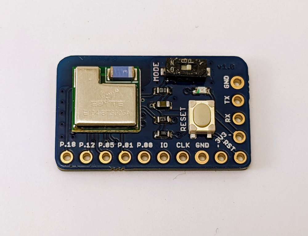
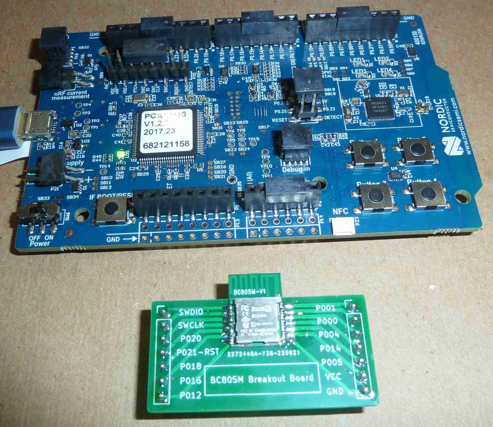
Update on my NRF52805 Breakout:
- I2C is now working, just a few small changes to select the right interface
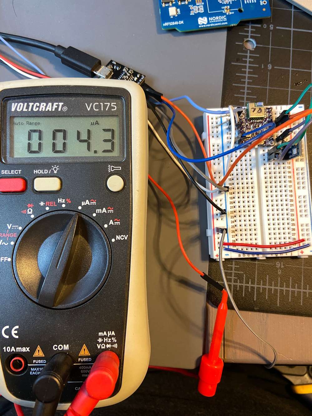
- Power consumption looks good, around 1.8uA. The Si7021 module is reading 2.5uA in isolation.
Just need to test SPI and figure out a clever name for the board, and should be good to go.
@ncollins Hey any update on your NRF52805 Breakout work? I've got a couple of the Ebyte modules that I have been playing around with. Found your pull request on GitHub for board support in sandeepmistry's nrf5 core. Wondering if you got any further as the pull request hasn't been merged and it would be great to see Arduino support for these modules.
-
@ncollins Hey any update on your NRF52805 Breakout work? I've got a couple of the Ebyte modules that I have been playing around with. Found your pull request on GitHub for board support in sandeepmistry's nrf5 core. Wondering if you got any further as the pull request hasn't been merged and it would be great to see Arduino support for these modules.
@Jon-Raymond I kinda got hung up on the last conversation in the merge request and haven't looked at it since. Let me push the changes I have to address the other comments, then try to figure out how to best handle that last bit.
-
@Jon-Raymond I kinda got hung up on the last conversation in the merge request and haven't looked at it since. Let me push the changes I have to address the other comments, then try to figure out how to best handle that last bit.
@ncollins That's great, thanks!
-
@ncollins Hey any update on your NRF52805 Breakout work? I've got a couple of the Ebyte modules that I have been playing around with. Found your pull request on GitHub for board support in sandeepmistry's nrf5 core. Wondering if you got any further as the pull request hasn't been merged and it would be great to see Arduino support for these modules.
@Jon-Raymond I pushed my latest changes, posted a question to the merge about next steps.
-
@Jon-Raymond I pushed my latest changes, posted a question to the merge about next steps.
@ncollins Here is my version of a breakout for the nRF52805.
Been playing around with your fork/pull request and I do have one question.
Should there be a SoftDevice for this? According to Nordic it needs either S112 or S113 for BLE to function? Right now your pull request only has the "None" option in the SoftDevice menu.
Is this something you have run into? Do you have any example code that you are running on this module? Thanks again for your work in getting this device supported.
-
@ncollins Here is my version of a breakout for the nRF52805.
Been playing around with your fork/pull request and I do have one question.
Should there be a SoftDevice for this? According to Nordic it needs either S112 or S113 for BLE to function? Right now your pull request only has the "None" option in the SoftDevice menu.
Is this something you have run into? Do you have any example code that you are running on this module? Thanks again for your work in getting this device supported.
@Jon-Raymond the nRF52805 should support the S112 and S113 soft device, but I removed it from the menu because I never tested it and didn't intend to immediately use it.
Digging through sandeepmistry/arduino-nrf5, it looks like S112 and S113 aren't included in the SDK. It might be easy enough to just drop in two new folders, then update boards.txt.
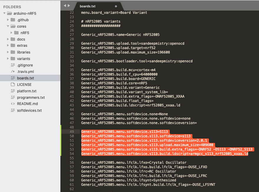
(Just an example of how I would add a soft device option to the dropdown, these would have to match up with whatever is in the sdk)
I would recommend opening an issue/question on https://github.com/sandeepmistry/arduino-nRF5, specifically asking the best way to add a new softdevice to the library. If it's straightforward, I can work with you to get those changes incorporated and, hopefully, included in the merge request.
-
@Jon-Raymond the nRF52805 should support the S112 and S113 soft device, but I removed it from the menu because I never tested it and didn't intend to immediately use it.
Digging through sandeepmistry/arduino-nrf5, it looks like S112 and S113 aren't included in the SDK. It might be easy enough to just drop in two new folders, then update boards.txt.
(Just an example of how I would add a soft device option to the dropdown, these would have to match up with whatever is in the sdk)
I would recommend opening an issue/question on https://github.com/sandeepmistry/arduino-nRF5, specifically asking the best way to add a new softdevice to the library. If it's straightforward, I can work with you to get those changes incorporated and, hopefully, included in the merge request.
Thanks @ncollins. I created the issue as requested.
-
Thanks @ncollins. I created the issue as requested.
@Jon-Raymond Well, not seeing a lot of activity in the repo.
I took a very long shot at adding support https://github.com/nikolac/arduino-nRF5/tree/nrf52805-s112-support.
I was able to flash the softdevice, but I haven't tested or even uploaded a working sketch (sloppy). Feel free to mess around and test. If it works for you, I do the same for S113.
Biggest question I have is around figuring out the proper values for the "linker scripts" https://github.com/nikolac/arduino-nRF5/blob/nrf52805-s112-support/cores/nRF5/SDK/components/softdevice/s112/toolchain/armgcc/armgcc_s112_nrf52805_xxaa.ld
-
I've ordered an Adafruit Clue, which should be arriving today. It utilizes the nRF52840. Judging from the reviews, Adafruit has done a nice job of supporting both the Clue and the Clue's vast number of built-in sensors with 1. good adafruit library integration along with lots of example programs and 2. the adafruit bootloader, making it easy for beginners to program the Clue via the familiar Arduino IDE. For those just getting started, I think it's likely to be a more satisfying experience and a gentler introduction to nRF5x than buying a nRF5x DK and then wondering what to do next.
I received the CLUE and it works very nicely--just like you'd expect a proper Arduino board to work: some basic hardware abstraction, a familiar easy-to-use Arduino IDE, easy familiar compiles, easy familiar uploads, and easy familiar access to serial input/output.
Time flies! This thread is already 5 years old, but I'm re-reading it now to refresh myself on all the little details that I've forgotten.
-
Anyone here programmed an nRF52805? I made a breakout board for one and was planning to program it using the J-LINK on an nRF52-DK:
but because there is no official DK for the nRF52805, there is no "board" for it, and so I'm unclear as to how exactly it is supposed to be programmed. Segger Embedded Studio makes no mention of the nRF52805 at all, as near as I can tell. Fortunately, our old friend Sandeep Mistry does appear to have a core for it: https://github.com/sandeepmistry/arduino-nRF5/tree/master/cores/nRF5/SDK/components/device
so that may help save the day. Unfortunately, the nRF52805 upload instructions from Nordic are a hassle: https://devzone.nordicsemi.com/guides/short-range-guides/b/getting-started/posts/developing-for-the-nrf52805-with-nrf5-sdk Is there no easier way? -
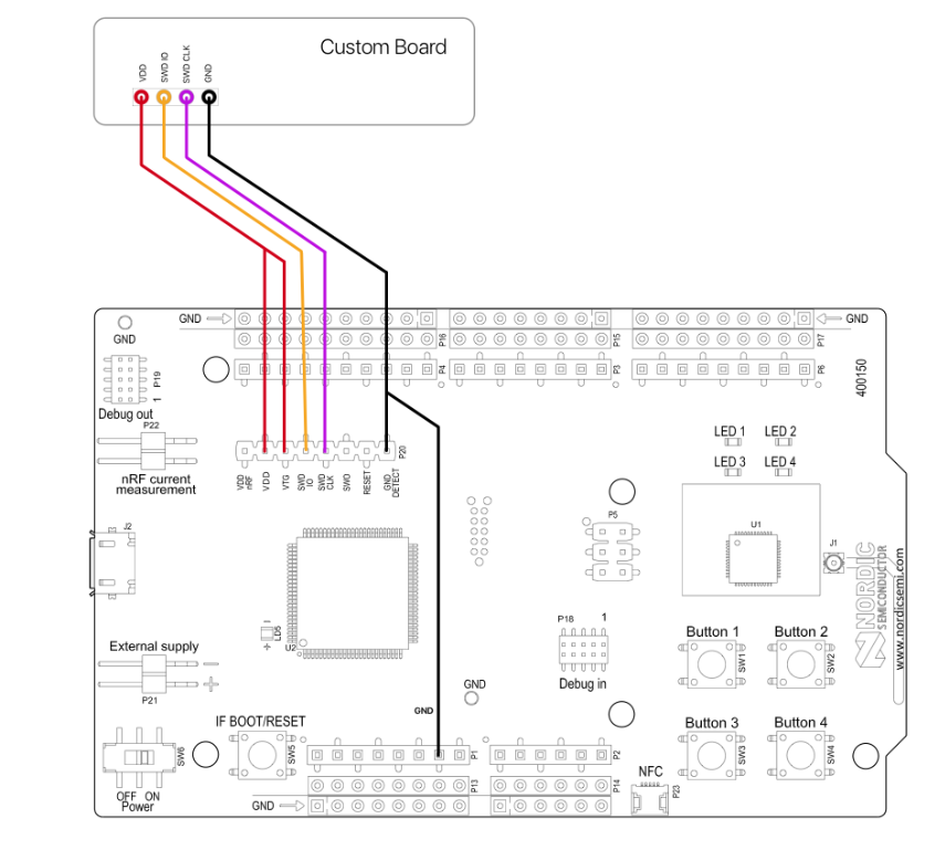
Reporting back: As a first step I programmed an external nRF52832 by blinking P.18 using this method for wiring it up: https://devzone.nordicsemi.com/f/nordic-q-a/14058/external-programming-using-nrf52-dk This method of wiring is worthy of note all by itself, because prior to now the conventional wisdom was that the target mcu had to be separately, externally powered for the J-link on the DK to recognize it properly. With the illustrated approach to wiring it up, though, you can power it from the DK itself.
Nice.That worked just fine. Then I tried uploading exactly the same code, using the same wiring scheme, to the nRF52805. I even erased it beforehand just to be sure.
According to J-Link, both the erasure and the subsequent upload were successful. However, P.18 does not blink. So, it would appear that a straightforward upload by treating it like an nRF52832 just isn't going to work, even just for blinking a particular pin. Argh! I feared as much. Disappointing! -
Success! Treating the nRF52805 like an nRF52810 and uploading to it from Segger Embedded Studio's IDE using Nordic's nRF52 SDK's PCA10040e board definition, then pin P.18 blinks using the same sketch that blinked P.18 on the nRF52832. I'm reporting back with this good news, because I haven't seen it tried or documented anywhere before. At least for this modest first attempt, this simple spoof works! At $2.50 each, these tiny nRF52805 modules with their trace antennas are a good value.
By the way, the compiler that's built into Segger Embedded Systems is super fast compared to gcc.