[solved] RS485 nodes stop sending data after some hours or days
-
So once more a short update: No significant changes achieved by changing the transmitters and the placing of the resistors - only two of 4 nodes are working as expected :sob: , the 5th (Node_2) is still turned off to prevent possible interference with Node_1.
As two of them are online since my last post (around 18 days), I'm quite sure, it's not a gw issue as @pjr reported, and as one of the nodes is powered from a different source than the other 3 and different than the GW, it seems also not to be powering related. So I'm a little running out of ideas how to further debug :sob: .
Now', Im thinking about reverting Baudrate back to 9600 and - in case this will not help (what most likely will happen) - splitting up the bus to two lines, this may help to find out what is going on with individual nodes.
So @otto001 At this point in time I'd say: It really depends...
If you have only a few nodes (2-3+GW) you want to attach, RS485 is a simple and secure option. But as soon as there are more, one failing will affect the entire communication - that's really no fun. So stay with nRF24 (or other wireless transceivers) for nodes just sending in data and try RS485 with a few important switching/security relevant nodes first.Just my2ct...
That is what I all time suggest use CAN bus drivers instead of 485 bus drivers.
CAN bus driver adds some safety, because disconnect microcomputer by hardware from bus, if it sends dominant state too long ( when program hangs etc. ).
So single node cannot damage all communication on the bus.And try different node ID than 1 - 4.
It maybe collides with packet wrapping characters, defined in standard ASCII table for 485 transport protocol in wrong situation.#define SOH 1
#define STX 2
#define ETX 3
#define EOT 4 -
That is what I all time suggest use CAN bus drivers instead of 485 bus drivers.
CAN bus driver adds some safety, because disconnect microcomputer by hardware from bus, if it sends dominant state too long ( when program hangs etc. ).
So single node cannot damage all communication on the bus.And try different node ID than 1 - 4.
It maybe collides with packet wrapping characters, defined in standard ASCII table for 485 transport protocol in wrong situation.#define SOH 1
#define STX 2
#define ETX 3
#define EOT 4@kimot Thx for reffering to CAN.
Some questions and remarks on that:- The Node ID's assigned in reality are 97 and higher, the node-# mentionned here are just for simplyfing explanation by following the physical order they are attached to the bus.
- How to setup a CAN network with MySensors? I saw some suggestions wrt to that in the past, but that seemed not to be "ready to use" code and hardware. So is there an option to just replace the MAX48x by a different chip and use the MyS-RS485 communication layer?
I have some MCP2515 modules laying around, but these use SPI as connection towards the mcu and would require an appropriate communication layer in the sketches (at least as far as I understood).
But in general, also standard RS485 claims to be robust and not rocket science tech. So it's really frustrating to experience that amount of problems and backdraws.
EDIT: I found this thread: https://forum.mysensors.org/topic/5327/can-bus-transport-implementation-for-mys. Most likely, really understanding most of it's content will need a lot of rereading. But as far as I understood, integration of CAN still would need a lot of development?
-
@kimot Thx for reffering to CAN.
Some questions and remarks on that:- The Node ID's assigned in reality are 97 and higher, the node-# mentionned here are just for simplyfing explanation by following the physical order they are attached to the bus.
- How to setup a CAN network with MySensors? I saw some suggestions wrt to that in the past, but that seemed not to be "ready to use" code and hardware. So is there an option to just replace the MAX48x by a different chip and use the MyS-RS485 communication layer?
I have some MCP2515 modules laying around, but these use SPI as connection towards the mcu and would require an appropriate communication layer in the sketches (at least as far as I understood).
But in general, also standard RS485 claims to be robust and not rocket science tech. So it's really frustrating to experience that amount of problems and backdraws.
EDIT: I found this thread: https://forum.mysensors.org/topic/5327/can-bus-transport-implementation-for-mys. Most likely, really understanding most of it's content will need a lot of rereading. But as far as I understood, integration of CAN still would need a lot of development?
@rejoe2
I am not meaning CAN protocol.
Only CAN bus drivers:
ebayRS485 is robust, but nod designed for multimaster communication, when two nodes can ocupy bus at the same time. CAN bus drivers are designed for this situation.
You can use CAN drivers like 485, only forgot about RE, DE.
CAN bus driver always listens.
And you must use higher speeds ( 57 600 ) because driver cut of controller if it sends dominant state longer then 250 μs ( byte 00hex must be send quickly then this timeout )
Or use MCP2551, where this time is 1.25 ms. ( 9 600 )
ebay -
@rejoe2
I am not meaning CAN protocol.
Only CAN bus drivers:
ebayRS485 is robust, but nod designed for multimaster communication, when two nodes can ocupy bus at the same time. CAN bus drivers are designed for this situation.
You can use CAN drivers like 485, only forgot about RE, DE.
CAN bus driver always listens.
And you must use higher speeds ( 57 600 ) because driver cut of controller if it sends dominant state longer then 250 μs ( byte 00hex must be send quickly then this timeout )
Or use MCP2551, where this time is 1.25 ms. ( 9 600 )
ebay@kimot Thanks for clarification, just ordered a bunch of TJA1050 modules and a couple of naked MCP2551 (seem to be pin compatible with the TJA's) :grin: . That may take some time for all the way from china (new year is coming...).
Next step then will be to change Baudrate to 57600 (seems to be the upper limit when using software-serial - as needed for my Nano-GW. Btw.: I did some really disappointing tests with a pro micro-GW, but that seemed not to work, I most likely will have to make another attempt on this to use HW-serial :grin: ).Then I'll replace the MAX48x-modules by these TJA's and see, if everything's fine then.
Just one remark: If it's as easy as that, wouldn't it be good to just recommend using that type of module as a standard instead of the problematic standard RS485 types?
EDIT: One more question: Mixing both (or all three) types of transceiver should be possible, or am I wrong? (This would not completely eliminate the MAX485-disadvantages, that's clear to me)
-
@rejoe2 :
Thanks a lot!
I am having some unusual sketches (washing mashine monitoring, entry-system with fingerprint) where I am using self-written sketches with mysensors). Maybe I should wait. It is just annoying that the radio-stuff is not always working as it should. Indeed, esp with mqtt could be a solution too. But I do not know yet about the stability of esp-stuff :-(Cheers,
Otto -
I had quite strange problem with my smaller network. There is a nano with enc28j60 shield as gateway and there was 2 relay/fet-nodes for controlling lights. Everything was fine until now I added one light switch node to the network. After that only the light switch was working. Strange...
Disconnected all the nodes from network and checked what is causing the problem. It was the GW. Measured the bus between A and B was ~2.5V. So it was pulling the bus to logical one all the time.
Changed the RS485 module.. no help. Then measured the "MY_RS485_DE_PIN" what I was using pin 2. The enc28j60 shield was pulling the pin to 0.6V and that was causing the RS485 shield to drive bus to ~2.5V. I changed the pin to 3 and now everything is working like a dream. Of course none of these nodes are sending all the time so most likely there wont be any collisions.
So when some node/bus is hanging next time measure the voltage of DE-pin :D
-
@mick Its still in use. I had one bus freeze since last "update post".
The gateway did pull the line up to 190mV what seems to be enough to get traffic frozen. After "reboot" of the gateway it was still pulling the bus to 160mV so it must be some solder on wrong place and bad chinese pin headers or protoboards.. I have to rebuild the "motherboard" of the gateway..
@pjr that sounds promising. My Serial gateway and one node ran for months with no problems. I’ve since added a node in between the two and that’s when I started having issues. Removing resistors on the middle node (terminating, pull-up and pulldown) and removing the pull-up and pull down on the end node seem to have fixed the issues for now however when I added an extra 20m to the cable run I started having issues again. I’de Love to get this network working 100% but I think a lot persistence and patience is needed! :)
-
Hints on RS-485 networks:
Termination resistors
You always need them. Termination resistors should be added to the nodes located at the ends of the line. The communication may works without them if the wire is short enough and/or the bit rate is low.Pull up/down resistors a.k.a failsafe bias resistors
Why you need it is well explained here: https://electronics.stackexchange.com/a/284788/88486
When you need it: It depends on the RS485 transceiver IC. Most modern transceivers include these.Common ground
Do you have a common ground between your transceivers? RS-485 is not a 2 wire network. Besides the A-B lines it requires ground.
See: http://store.chipkin.com/articles/rs485-rs485-cables-why-you-need-3-wires-for-2-two-wire-rs485
Schematics at http://www.analog.com/media/en/technical-documentation/application-notes/AN-960.pdf page 4.Isolation
When you deal with long links, you have to take care of isolation.
Page 8 at http://www.analog.com/media/en/technical-documentation/application-notes/AN-960.pdf -
@kimot Thanks for clarification, just ordered a bunch of TJA1050 modules and a couple of naked MCP2551 (seem to be pin compatible with the TJA's) :grin: . That may take some time for all the way from china (new year is coming...).
Next step then will be to change Baudrate to 57600 (seems to be the upper limit when using software-serial - as needed for my Nano-GW. Btw.: I did some really disappointing tests with a pro micro-GW, but that seemed not to work, I most likely will have to make another attempt on this to use HW-serial :grin: ).Then I'll replace the MAX48x-modules by these TJA's and see, if everything's fine then.
Just one remark: If it's as easy as that, wouldn't it be good to just recommend using that type of module as a standard instead of the problematic standard RS485 types?
EDIT: One more question: Mixing both (or all three) types of transceiver should be possible, or am I wrong? (This would not completely eliminate the MAX485-disadvantages, that's clear to me)
-
@mick Thanks for coming back to this topic, the stuff arrived already some weeks ago, but unfortunately I was busy with other parts, amongst them btw. a modification of the MySensors plugin for FHEM to get probems shown more easily. So finally some soldering work was on my list yesterday. So today there's the option to at least give some first impressions on that:
- Network is @57600 for the use of the TJA1050 modules.
- Soldered some adopter boards for direct replacement of the modified LC-Tech MAX487 modules, (crossed RX/TX as usual, there's no DE/RE, later also desoldered the 120 Ohm resistor)
- plugged it in Node_2's socket, and
WOW: It worked!
Tried a second one on the same node (module without the 121R): Also worked :smile:
So I continued and tried to teplace the transceiver at Node_3 with the tested (now resistorless) one:
NO LUCK!
Continued with the last transceiver in line holding the pullup/dow resistors: Also no luck :unamused:
So I decided to stop at that point to see how Node_2 will perform over night and meditate on the question why the behaviour on the other two nodes is different. Kept Node_1 and Node_4 not connected to the bus, so starting the experiment just with 3 nodes and the GW online.
This mornings's findings:
- (Node_2 hat at least once spontanously rebooted, but still was sending in data. I's rate this as some kind of partly success, but obviously the node needs to be reviewed, there most likely exists a problem not related to RS485.)
- (Node_5 was offline for whatever reason, no issues - as always - on Node_3)
- These transceivers can be used for MySensors@RS485
- They can be used in a mixed network together with normal transceivers
- BUT: (hypothesis) They may not be used in combination with altSoftSerial; Node_2 is HW-Serial, the other two still use software, so for them DE/RE might be essential (ISR?)
Additional remarks: I tried also a different power source for the 12V a couple of weeks ago - no difference (MAX487-only bus)
The GW was online during all of the time, it's uptime is 7 days by now (also SW-serial).So I'll have to do some more testing on some of the topics and perhaps also build some more test nodes to avoid touching my "normal" bus too often - this seems to also cause additional trouble...
I'll come back when I know more, but again, this will take some time.
@bakcsa Thanks for this great summary!
-
I think the problem is not from the RS485 side, not from cabling etc. I have similar problems on my RS485 network, some nodes stop sending data for no reasons after some time (sometimes 2 days sometimes 4 weeks). I have changed from AltSoftSerial to HWSERIAL and its the same.. Maybe its about ENABLE PIN 2 ?? Anyone try to change this pin to other ??
@nofox Did you measure voltages on the bus?
Some additional info: I did some futher experiments using also MCP2551 as transceiver chip. As they are PIN-compatible to the TJA's, it was just a modification of the modules. I can confirme thess also to work.
General "restriction" is one has to use HW-serial. For me, that's ok, but if you want serial output for debugging, you also have to use altSoftSerial and use it for debug output.This morning, I replaced the end-of-line module with a resistorless one (so also NO termination resistor is used on this side, only at the GW!).
At least, the Bus is working for some minutes now @56700 with just GW (MAX487) and one node for each of the tranceiver chips (MAX487, MCP2551 and TJA1050).
If that works more reliable, I'll switch all nodes to MCP2551 and lower the transmission rate, most likely to 19200 Baud. Will take again some time, but I'll keep you updated. For this I plan to use a STM32F103 as GW, if possible, I'll try to expose also the other two Serial Interfaces to the OS, so one could attach up to two other GW's (for other physical transport layers) to the STM using just one USB connection. But that's another project on another planet and if there's someone out there with more experience on how to do that: Thank's a lot...
-
Anyone know how to implement this https://github.com/MichaelJonker/HardwareSerialRS485/wiki to mysensors ? It can operate in multimaster mode and avoid collision issues.
Found this some days ago: https://github.com/mysensors/MySensors/pull/1142
Adding these changes to a 2.3.0-alfa base seem to make a big difference in reliability :grinning: .
So if there's other users having similar problems: please make also some testing of this patch.
You will get further updates and some more info on my recent setup, so far: Thanks a lot for all the ideas and hints to improve things!
-
As everything still seems to work as expected some futher remarks on my findings/hypothesis and todays setup:
General remark: As a lot of things have changed over time and some of my tests turned out to be contraproductive, it's hard to sort out THE root cause now. But as others had some issues with colliding messages too, I'd bet on that and really appreciate if the patch #1142 would find it's way to everyones codebase (@seeers seems to have some issues at github, can one of the mods help him out of that, please?) :grinning:.
Back to my setup:
- Nodes are powered now through a central 5V DC supply, only 3.3V conversion remains locally, GW through USB
- GND of central 5V is not connected to GW GND (in case of trouble, I'd add a "resistored" connection)
- All nodes use Hardware-Serial, Baudrate is @19200
- No debugging messages on nodes activated (if someone wants/needs it: swap debugging output to altsoftserial...)
- Transceiver used: MCP2551, most of them on modded TJA1050-Boards (don't forget to dissolder the R120) => no DE-Pins necessary
- Gateway is a Pro Micro
- Termination resistors: 2kOhm at the last node in line (CANhi->5V and CANlo->GND), 120Ohm (A-B) only at last node and GW
Remarks:
- My long-time GW was a regular MAX485/MAX487-Nano using AltSoftSerial. IMO this over time had been one of the most reliable components in my setup. Conclusion: Most likely this lib is NOT to blame for any trouble I ran into.
- Nevertheless hanging nodes with regular RS485 trasceivers caused problems to some extend. So I really like the CAN logic to switch the transceiver off when it's MC seems not to work properly to avoid infection of communication from other nodes. What I didn't test yet: Using CAN transceivers together with altSoftSerial. So expect some additional info on that later, as this might be helpful for debugging over USB as on any other node
- To some extend all of the transceivers seem to be able even to transmitt in case A-B voltage level is above the "critical value" - depends a little on the strength of the power source. So I'd see this just as some type of "most likely" indicator of a bus problem now.
Hope someone might find that summary helpful and once again:
Thanks a lot to all those people here and at FHEM-forum trying to help me out of that never ending mys(t)ery! :grin: :clap:
-
Thanks for helping @seeers at Github.
Still no communication issues to report, so just two additional remarks on the MCP2551 usage following some short tests on that:
They also seem to work at 9600 Baud and also using the MySensors standard (AltSoftSerial at PINs 8 and 9) is possible.So for now, I'd recommend everybody thinking about new nodes to give this type of hardware a try. The only disadvantages may be
- the limitation in payload - but that seems not to be any practical issue in the use in an MySensors environment
- they might be more sensitive in crossing BusHigh and BusLow connection, so make sure all highs are on the same wire and also all lows :grin:
My favorites are kind of violet modules. Didn't come across them earlier, so I'd see all PINs on one side as a modest point for improvement. As there are also no resistors at all, just pads for soldering, there's also not the need of starting with desoldering unnecessary parts - just make sure, you have the right stuff to add :stuck_out_tongue_winking_eye: .
-
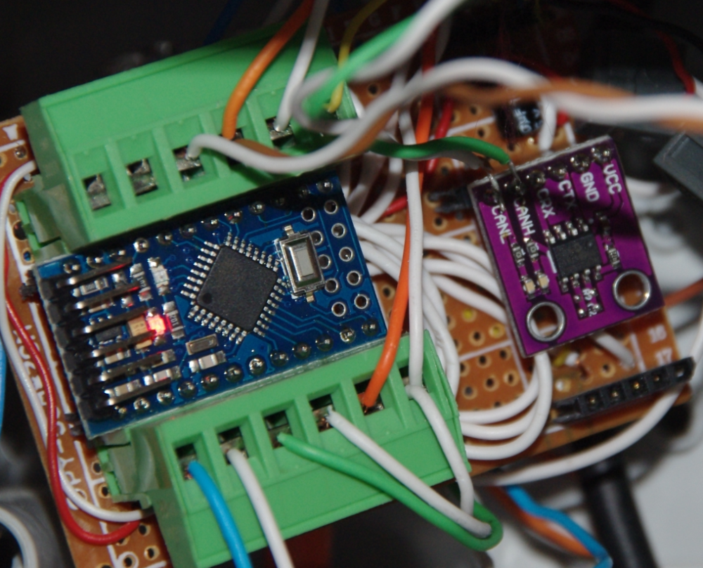
Everything's working like a charm now :grinning: , so thread is marked as [solved] now.
One more big "Thank you" to everybody helping to get this finally done :confetti_ball: :clap: !In addition a picture of my Node 2 - the one I did the most rework over time until now also showing the violet MCP2551 module mentionned above.