Car Aux Battery Monitor
-
@Boots33 For the radio, what if you used an NRF24L01+PA+LNA with an external antenna. you could put rubber washers on it to keep dirt out while having the antenna external to the other electronics.
Just a thought.
@dbemowsk an external antenna is a good idea. I would like to avoid an amplified nrf if I could though simply because the le33 probably wouldn't cope.
Has anyone fitted an antenna socket to a standard nrf before.
I am happy enough with plugging in the unit at the moment but am also thinking of adding a few more features that will be useful when away. Then it would be better to have a mounted unit. -
@dbemowsk an external antenna is a good idea. I would like to avoid an amplified nrf if I could though simply because the le33 probably wouldn't cope.
Has anyone fitted an antenna socket to a standard nrf before.
I am happy enough with plugging in the unit at the moment but am also thinking of adding a few more features that will be useful when away. Then it would be better to have a mounted unit.@Boots33 there are versions with SMA connector that don't have the PA part ;)
I have also sometimes modified a "standard" NRF24L01+ module with a IPX connector
- Tomas
-
@Boots33 there are versions with SMA connector that don't have the PA part ;)
I have also sometimes modified a "standard" NRF24L01+ module with a IPX connector
Thanks @korttoma didn't know about those, have ordered a couple to give them a try. :)
They will come in handy if I decide to add further to this node and make it a permanent mount.
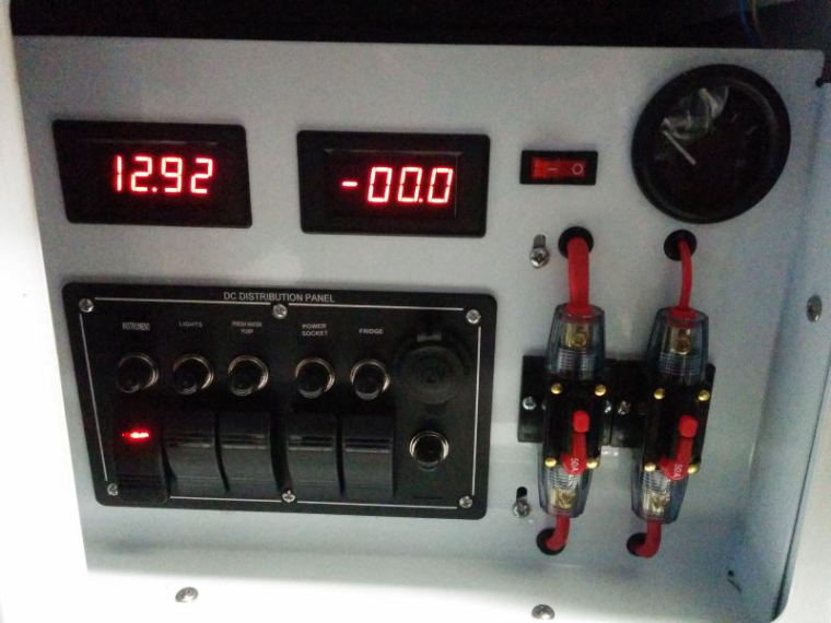
The camper has a control panel that includes an ammeter and volt gauge to help monitor the batteries, it is pretty basic but does a good job for what it is. It uses a shunt (75mv 100A) for the ammeter so I should be able to tap into that and add current draw to my data.
It also has a fridge box which has little ventilation at the moment so the fridge has to work hard in the hotter weather. We will be travelling into some desert areas next year so a temperature controlled ventilation system may be of use.
All just ideas at the moment will see how it progresses.
The control panel
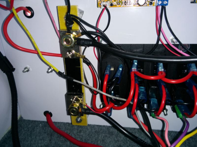
The shunt is mounted on the rear of the panel
-
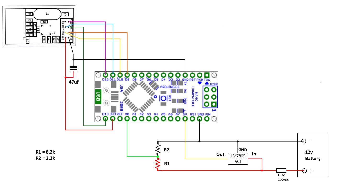
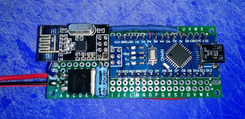
The low power node is now working as intended, the addition of an extra 47uf for the nrf power pin (there are two there now so a total of near 100uf) and an aditional .1uf on the LE33 power pin has made the node stable. It shows just how fussy the nrf can be about its power requirements.
I have made the changes to the wiring diagram in the previous post to reflect these additions.
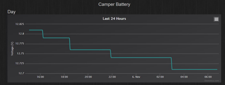
Have also now had a chance to compare the graphs of the two nodes in Domoticz and the low powered node with voltage averaging seems to give a much better result. In the following pictures you can see the steady drop of voltage over time for the low power node and a more zigzag line for the original node.
Will not know for sure until I add averaging to the first node, maybe the extra power draw is also affecting the reading.
The original node
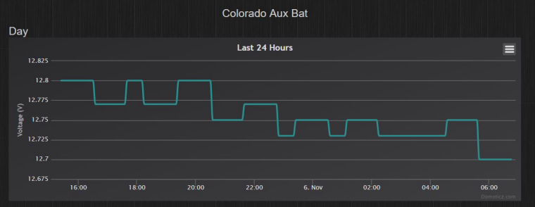
The low powered node. These are both connected to the same vehicle at the moment.