Skip to content
  • MySensors
  • OpenHardware.io
  • Categories
  • Recent
  • Tags
  • Popular
Skins
  • Light
  • Brite
  • Cerulean
  • Cosmo
  • Flatly
  • Journal
  • Litera
  • Lumen
  • Lux
  • Materia
  • Minty
  • Morph
  • Pulse
  • Sandstone
  • Simplex
  • Sketchy
  • Spacelab
  • United
  • Yeti
  • Zephyr
  • Dark
  • Cyborg
  • Darkly
  • Quartz
  • Slate
  • Solar
  • Superhero
  • Vapor

  • Default (No Skin)
  • No Skin
Collapse
Brand Logo
  1. Home
  2. My Project
  3. $8 Lamp (Outlet) "Smart Plug" Module

$8 Lamp (Outlet) "Smart Plug" Module

Scheduled Pinned Locked Moved My Project
109 Posts 34 Posters 97.5k Views 13 Watching
  • Oldest to Newest
  • Newest to Oldest
  • Most Votes
Reply
  • Reply as topic
Log in to reply
This topic has been deleted. Only users with topic management privileges can see it.
  • Z Zeph

    Another interesting (albeit long) video testing range of various modules and antennae.

    https://www.youtube.com/watch?v=gtM832Z0ujE

    The interoperability of different types is somewhat surprising. Some had only a 2/3 packet success ratio even at close range, but retained that for a long distance, for example. He did try cap vs no cap, and with "whip" (really more of a stubby or rubber ducky style) antenna parallel or with one pointing at the other. The unit with PA+LNA and shield was overall pretty good for range.

    petewillP Offline
    petewillP Offline
    petewill
    Admin
    wrote on last edited by
    #91

    @Zeph thanks for sharing. Always better to have more info and hopefully better range!

    My "How To" home automation video channel: https://www.youtube.com/channel/UCq_Evyh5PQALx4m4CQuxqkA

    1 Reply Last reply
    0
    • sundberg84S sundberg84

      @petewill
      Now i got three working relays thanks to you, so again, great video!
      Wanted to thank you and also show my sollution.
      I hade some 433mhz cheap (not good working) relays with perfect case i could re-use:
      The case had a status-led and a switch i use as well.

      Relay.jpg

      D Offline
      D Offline
      dayve218
      wrote on last edited by
      #92

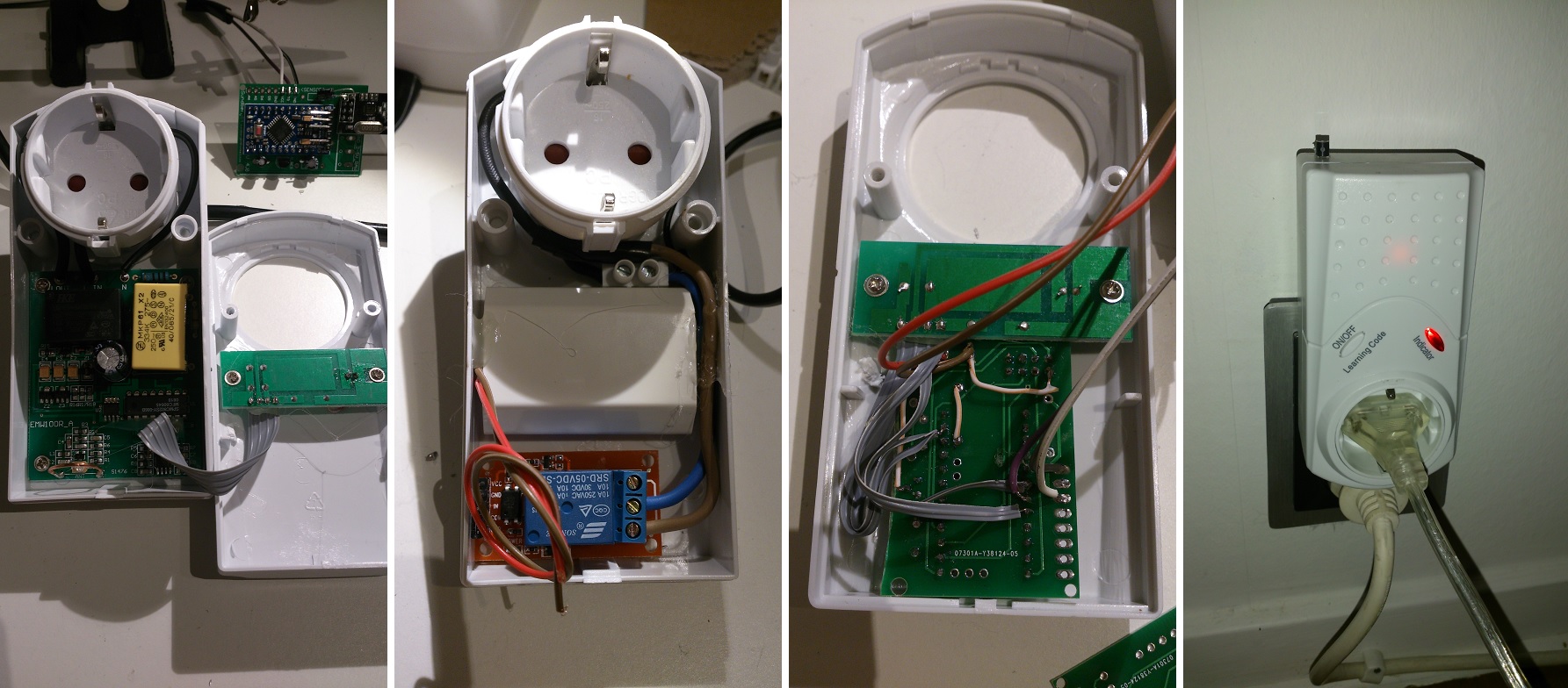
      @sundberg84 how are you powering the arduino?

      1 Reply Last reply
      0
      • sundberg84S Offline
        sundberg84S Offline
        sundberg84
        Hardware Contributor
        wrote on last edited by
        #93

        @dayve218
        Im using a USB charger as pete does in the video but mine is a iphone charger instead of a samsung.

        Controller: Proxmox VM - Home Assistant
        MySensors GW: Arduino Uno - W5100 Ethernet, Gw Shield Nrf24l01+ 2,4Ghz
        MySensors GW: Arduino Uno - Gw Shield RFM69, 433mhz
        RFLink GW - Arduino Mega + RFLink Shield, 433mhz

        1 Reply Last reply
        0
        • D Offline
          D Offline
          dakipro
          wrote on last edited by
          #94

          Nice project, both Petewill and sundberg84.
          I was just wandering if you @sundberg84 know more about what is the device type/model/manufacturer you were moding?

          I've used quite some time and effort to find localy some good case that I can modify, I did manage to hack some of them but they are just not quite reliable (something with power just kills caps too often).

          Thanks in advance, sorry for bringing up old topic (but it is a very good one :) )

          C: OpenHAB2 with node-red on linux laptop
          GW: Arduino Nano - W5100 Ethernet, Nrf24l01+ 2,4Ghz mqtt
          GW: Arduino Mega, RFLink 433Mhz

          1 Reply Last reply
          0
          • sundberg84S Offline
            sundberg84S Offline
            sundberg84
            Hardware Contributor
            wrote on last edited by
            #95

            @dakipro - Its a low brand 433mhz wall plugs i bought in Sweden called Everflourish emw100r. I dont think they are sold anymore. Its probably some china brand so maybe they are sold in another name.

            Controller: Proxmox VM - Home Assistant
            MySensors GW: Arduino Uno - W5100 Ethernet, Gw Shield Nrf24l01+ 2,4Ghz
            MySensors GW: Arduino Uno - Gw Shield RFM69, 433mhz
            RFLink GW - Arduino Mega + RFLink Shield, 433mhz

            1 Reply Last reply
            0
            • dbemowskD Offline
              dbemowskD Offline
              dbemowsk
              wrote on last edited by
              #96

              So I have been thinking of building some relay controlled power strip nodes similar to these, but there have been some issues that I have been thinking about. The first is that if I am going to use a relay to turn on an outlet, the relay would need to be powered the entire time that I would want that device on. This would mean that not only am I powering the device that is plugged in, but the power to keep the relay on also. Wouldn't it be smarter to use latching relays? At least with those you don't need to keep power to the relay while your outlet is on. Has anyone ever done a MySensors node with latching relays? If so, how do you manage monitoring the state of the device?

              Vera Plus running UI7 with MySensors, Sonoffs and 1-Wire devices
              Visit my website for more Bits, Bytes and Ramblings from me: http://dan.bemowski.info/

              1 Reply Last reply
              0
              • D Offline
                D Offline
                dakipro
                wrote on last edited by
                #97

                out of the curiosity, what is downside of powering the relay entire time?
                that is how (all) wall switches work out of the box, you press the button and they turn on/off by powering the relay (all the time).
                I think that they work quite reliably when it comes to keeping power to the reley

                C: OpenHAB2 with node-red on linux laptop
                GW: Arduino Nano - W5100 Ethernet, Nrf24l01+ 2,4Ghz mqtt
                GW: Arduino Mega, RFLink 433Mhz

                dbemowskD 1 Reply Last reply
                0
                • D dakipro

                  out of the curiosity, what is downside of powering the relay entire time?
                  that is how (all) wall switches work out of the box, you press the button and they turn on/off by powering the relay (all the time).
                  I think that they work quite reliably when it comes to keeping power to the reley

                  dbemowskD Offline
                  dbemowskD Offline
                  dbemowsk
                  wrote on last edited by
                  #98

                  @dakipro I wouldn't say that ALL wall switches work that way. And when you say (all) wall switches, what are you referring to? Standard (non automated) wall switches don't use relays. Also, most if not all of the X10 relay modules and wall switches that I have use latching relays.

                  Vera Plus running UI7 with MySensors, Sonoffs and 1-Wire devices
                  Visit my website for more Bits, Bytes and Ramblings from me: http://dan.bemowski.info/

                  1 Reply Last reply
                  0
                  • D Offline
                    D Offline
                    dakipro
                    wrote on last edited by
                    #99

                    I meant these typical automated/controlled wall switches mentioned in the topic http://www.nexa.se/vara-produkter/system-nexa/mottagare-paav/eycr-2300
                    I opened 6-7 different ones to find the right casing for some projects, and they all had "regular" relay that goes back when the power is off (thus being powered the whole time). Of course I didn't open every single one of them, that is why I put (all) in parentheses.
                    I am also not the expert on the relay topic, that is why I asked what is the downside :)

                    C: OpenHAB2 with node-red on linux laptop
                    GW: Arduino Nano - W5100 Ethernet, Nrf24l01+ 2,4Ghz mqtt
                    GW: Arduino Mega, RFLink 433Mhz

                    1 Reply Last reply
                    0
                    • petewillP petewill

                      Hi All,

                      I created a second "Smart Plug" and thought I'd make a how to video this time. I have found them very useful for controlling various devices around the house. It's long but hopefully will be good for everyone including those not too familiar with MySensors. I know when I was first starting out I had little to no experience with any of this stuff and it was hard to piece it all together.

                      http://youtu.be/oNpMDN4QqD8

                      Here is the parts list (most of this stuff can be obtained from the my sensors store so don't forget to support them!)

                      • 1 Gang Outlet Box
                      • Outlet
                      • Computer power cord or extension cord
                      • Old cell phone charger or some other 5v power supply
                      • Items from MySensors Store http://www.mysensors.org/store/
                      • 22-24 gauge wire or similar (network cord)
                      • Female Pin Header Connector Strip
                      • Prototype Universal Printed Circuit Board
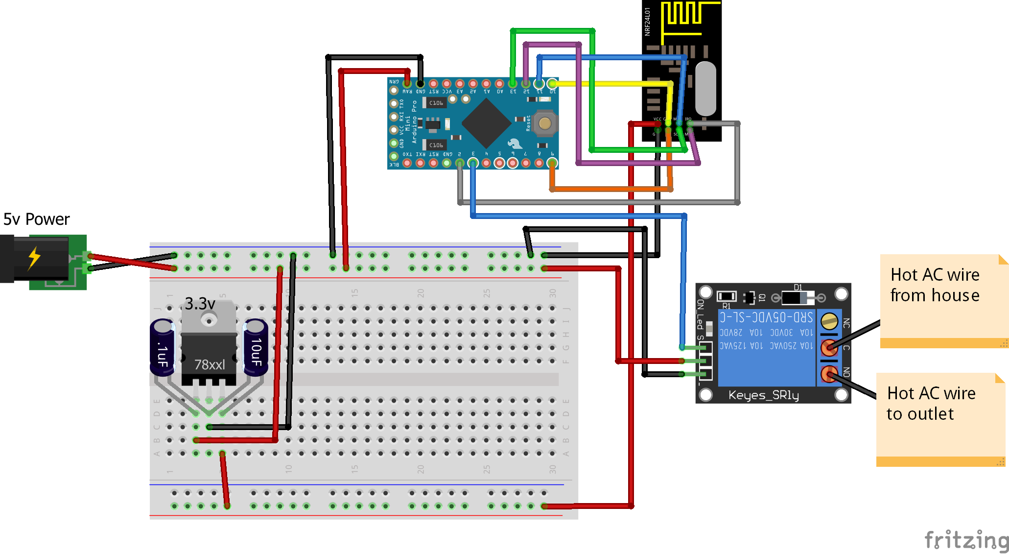
                      • NRF24L01 Radio
                      • Arduino Pro Mini
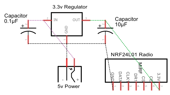
                      • Capacitors (10uf and .1uf)
                      • 3.3v voltage regulator
                      • Female Dupont cables

                      Here is a wiring diagram for the 3.3v regulator:
                      Voltage Regulator Schematic.png

                      0_1467849909161_Fritzing Smart Outlet.png

                      Here is the code I used. I made a few customizations but the example "Relay Actuator" code can be used as well.
                      https://codebender.cc/sketch:72358

                      *edited to add wiring diagram

                      Christian TollasC Offline
                      Christian TollasC Offline
                      Christian Tollas
                      wrote on last edited by
                      #100

                      @petewill greetings sir.. Im getting error in your source code.. Maybe imported a wrong library.. Sir can i ask where did u get your MySensors.h library.. I get mine in codebender..

                      My error is..

                      MySensor gw;

                      MySensor does not a nametype

                      petewillP 1 Reply Last reply
                      0
                      • Christian TollasC Christian Tollas

                        @petewill greetings sir.. Im getting error in your source code.. Maybe imported a wrong library.. Sir can i ask where did u get your MySensors.h library.. I get mine in codebender..

                        My error is..

                        MySensor gw;

                        MySensor does not a nametype

                        petewillP Offline
                        petewillP Offline
                        petewill
                        Admin
                        wrote on last edited by
                        #101

                        @Christian-Tollas This code has not yet been updated for MySensors version 2.0. I am still on version 1.5. When I finally upgrade my setup to 2.0 I will post the updated code but I'm not sure when that will be. If you want to go back to 1.5 for the time being that should work for you.

                        My "How To" home automation video channel: https://www.youtube.com/channel/UCq_Evyh5PQALx4m4CQuxqkA

                        1 Reply Last reply
                        0
                        • D Offline
                          D Offline
                          dseveriano
                          wrote on last edited by dseveriano
                          #102

                          Hello,

                          I'm newbie at this and I'm trying to make this, but I think my hardware needs to be different sinces my home voltage is arround 220V, does this hardware can handle this voltage or do I need to buy other capacitators ?

                          Thanks

                          petewillP 1 Reply Last reply
                          0
                          • D dseveriano

                            Hello,

                            I'm newbie at this and I'm trying to make this, but I think my hardware needs to be different sinces my home voltage is arround 220V, does this hardware can handle this voltage or do I need to buy other capacitators ?

                            Thanks

                            petewillP Offline
                            petewillP Offline
                            petewill
                            Admin
                            wrote on last edited by
                            #103

                            @dseveriano as always you need to be very careful when using these voltages. That being said, this should work without any other hardware except for a phone charger rated for 220 (which I believe most are). The relay I used was rated for 10A 250VAC. I wouldn't go as high as 10A though.

                            My "How To" home automation video channel: https://www.youtube.com/channel/UCq_Evyh5PQALx4m4CQuxqkA

                            D 1 Reply Last reply
                            0
                            • petewillP petewill

                              @dseveriano as always you need to be very careful when using these voltages. That being said, this should work without any other hardware except for a phone charger rated for 220 (which I believe most are). The relay I used was rated for 10A 250VAC. I wouldn't go as high as 10A though.

                              D Offline
                              D Offline
                              dseveriano
                              wrote on last edited by
                              #104

                              @petewill Thank you, just one more question!
                              What board is that, the red one where the relay is ? Is that necessary or can I put the relay in the same board ?

                              petewillP 1 Reply Last reply
                              0
                              • D dseveriano

                                @petewill Thank you, just one more question!
                                What board is that, the red one where the relay is ? Is that necessary or can I put the relay in the same board ?

                                petewillP Offline
                                petewillP Offline
                                petewill
                                Admin
                                wrote on last edited by
                                #105

                                @dseveriano Sorry, I'm not sure what you're asking. What board are you referring to?

                                My "How To" home automation video channel: https://www.youtube.com/channel/UCq_Evyh5PQALx4m4CQuxqkA

                                D 1 Reply Last reply
                                0
                                • petewillP petewill

                                  @dseveriano Sorry, I'm not sure what you're asking. What board are you referring to?

                                  D Offline
                                  D Offline
                                  dseveriano
                                  wrote on last edited by dseveriano
                                  #106

                                  @petewill Sorry the board I was refering was the relay board!!
                                  Regarding the current detection module wich one do you recommend ?

                                  petewillP 1 Reply Last reply
                                  0
                                  • D dseveriano

                                    @petewill Sorry the board I was refering was the relay board!!
                                    Regarding the current detection module wich one do you recommend ?

                                    petewillP Offline
                                    petewillP Offline
                                    petewill
                                    Admin
                                    wrote on last edited by
                                    #107

                                    @dseveriano Yes, the red board is the relay board which will control your 220V power.
                                    I haven't done much with current detecting but the module I was playing with was the ACS712. I found that even when no power was running through it there was still a few watts reported. Maybe that's a simple fix but I never really looked into it.

                                    My "How To" home automation video channel: https://www.youtube.com/channel/UCq_Evyh5PQALx4m4CQuxqkA

                                    1 Reply Last reply
                                    0
                                    • jeremushkaJ Offline
                                      jeremushkaJ Offline
                                      jeremushka
                                      wrote on last edited by
                                      #108

                                      Did you integrate power meter function to your systeme?

                                      petewillP 1 Reply Last reply
                                      0
                                      • jeremushkaJ jeremushka

                                        Did you integrate power meter function to your systeme?

                                        petewillP Offline
                                        petewillP Offline
                                        petewill
                                        Admin
                                        wrote on last edited by
                                        #109

                                        @jeremushka I haven't done it on the smart outlet but I did do it on my "Whole House Fan" project. You can check out the code from that if you're interested. Here is a link to the video if you wanted to check that out: https://youtu.be/KVsUe7sOCPo
                                        Also, just make sure you check out the specs on the acs712 and don't pass through more current than is safe. I don't remember the specs off the top of my head but I knew my whole house fan was safe because of what it would be drawing

                                        My "How To" home automation video channel: https://www.youtube.com/channel/UCq_Evyh5PQALx4m4CQuxqkA

                                        1 Reply Last reply
                                        0
                                        Reply
                                        • Reply as topic
                                        Log in to reply
                                        • Oldest to Newest
                                        • Newest to Oldest
                                        • Most Votes


                                        20

                                        Online

                                        11.7k

                                        Users

                                        11.2k

                                        Topics

                                        113.1k

                                        Posts


                                        Copyright 2025 TBD   |   Forum Guidelines   |   Privacy Policy   |   Terms of Service
                                        • Login

                                        • Don't have an account? Register

                                        • Login or register to search.
                                        • First post
                                          Last post
                                        0
                                        • MySensors
                                        • OpenHardware.io
                                        • Categories
                                        • Recent
                                        • Tags
                                        • Popular