How to interface MySensors with a 24V humidifier?
-
For the mysensorization of my air humidifier, I'm trying to interface the arduino with the 24V circuit of the humidifier.
I have some rought schematics in mind, but as I have practically no experience designing electronic cirvuits, I have no idea whether there are better solutions. So I desperately need some input from someone with more knowledge in circuit design. I would be very thankful if you could give me some feedback on my schematics as detailled below.Basically, the questions are how to best convert 24V to 5V/3.3V to power the arduino, whether a MOSFET is the best way to emulate a button press and whether voltage dividers are the correct approach to detect a button press and a burning LED.
The humidifier has the following items that I'm interested in:
- Power button (simple press)
- Switch to detect an open enclosure
- LEDs for Power On/Off and for Error
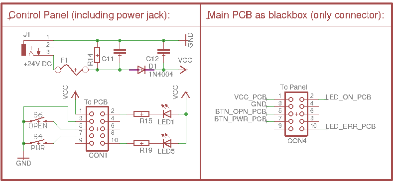
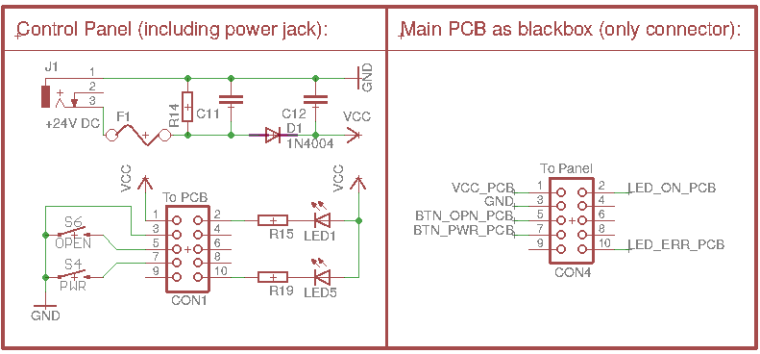
How to tap into the electronics of the humidifier
The PCB of the humidifier is mainly covered by a large motor, so tapping directly into the microcontroller is not an option (which is also covered by the motor; I can only see the last few characters: 1933, so it is probably a PIC16F1933). However, the control panel (with control buttons, LEDs and also the 24V power jack) is connected through a 10-pin ribbon cable, where I can easily place my own pcb. The ribbon cable provides +24V, GND, and the control buttons connect directly to GND, while the leds connect to +24V. Here's the schematic of the humidifier's existing control panel and the existing connector, where I want to interface:
What I am interested in:
- Emulating the Power button from MySensors
- Detecting the Open button (case open warning!) from MySensors
- Detecting which LED is on (to determine state and/or error)
- (Potentially, turn on the error LED from MySensors node, but that's for future use)
All lines of the cable run a voltage of up to 24V (some have ~19-20V measured with a multimeter), so I can't directly feed them into the Arduino.
So, my issues now are:
- Powering the arduino from the 24V, 0.5A power supply (pins 1+3 of the connector)
- Triggering a button press on pin 7 (simply connect pin 7 to GND, but need to take care of 24V level!)
- Detecting a button press on pin 5 (detect pin 5 going to GND, again with a voltage of 24V)
- Detecting which LEDs are on (as the LEDs are connected to +24V, I suppose this also means detecting pins 2 and/or 10 going from HIGH to GND)
If I measure the voltage at the lines using the arduino, how can I make sure not to influence the existing circuit of the humidifier?
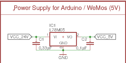
1) Powering the arduino from 24V:
Is it safe to use the GND from the 24V all through my own mysensors PCB with arduino pro mini, nrf24l01+, etc. and only transform +24V to +5V? Or is it better to directly transform to 3.3V and use the 3.3V of the pro mini?
My current idea is to simply use a linear voltage regulator like the L78M05:
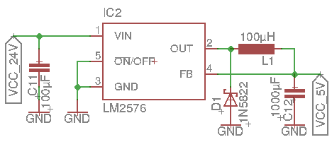
Or should I better use a step-down converter (a little more expensive, more parts, harder to route on the PCB) even though the arduino will never, ever use the 3A:
Do you think this will produce a proper power supply for the arduino? I'm afraid to try it out without first getting some second opinions, as this is my first hardware-design project, and I don't want to destroy either my humidifier or the arduino+nrf24...
2) Triggering a Power button press from MySensors
As a button press of the existing hardware buttons simply means connecting to GND, my idea was to use a simple MOSFET transistor (that can handle 24V) parallel to the existing hardware button, i.e.
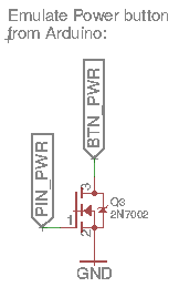
PIN_PWR would be connected to e.g. the D3 pin of the pro mini.Would this work to trigger a Power button press from the arduino?
Would you use this transistor or a different transitor? Or would you even recommend optocouplers to cleaner separate the 5V/3.3V circuit of the arduino from the 24V of the humidifier?
3) Detecting if the Open button was pressed (i.e. the enclosure is open)
As far as I can see, this simply means checking wether the corresponding wire goes to GND. As the internal microcontroller must observe this line, too, I suppose there is some pull-up already in place, so my idea was to simply use a voltage divider from 24V to ~5V to feed the line into the arduino:
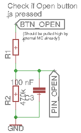
Again, PIN_OPEN is a digital pin (D4) of the arduino.Is using a voltage divider the correct approach here? Or are there better ways to detect BTN_OPEN going from high to GND?
What would be good values for the voltage divider's resistors? I thought of 470k for R2 and 2.2M for R1 (=> 4.22V from 24V).Is there anything I can do to minimize interference with the internal button press detection of the humidifier? No idea, how the internal circuit works and how the PIC16F1933 detects the button press, in particular, I have no idea about existing pull-ups and other components.
4) Detecting which LEDs are on
Strangely, the LEDs are connected to +24V (with a series resistor), so I suppose they are turned on by the internal MC by putting the corresponding pin low.
Does this mean that I can detect a burning led similar to the way I detect the button press? I.e. using a voltage divider and then simply piping into an input pin on the arduino (no pullups needed, obviously):
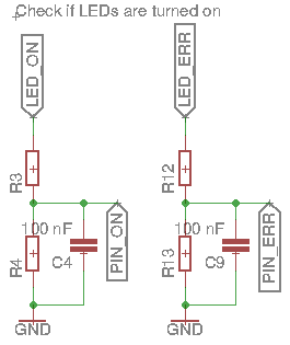
What worries me here is that this basically means I have only the LED, the 10k resistor (on the existing control panel of the humidifier), and the two resistors of the divider in series between +24V and GND, so basically just the LED and a large resistor (10k + ~2-3M). Is this really a good approach?
Any better idea how to detect whether any of the LEDs is on?
What do you think about this project? Are my approaches working at all, and are there better solutions to the issues at hand?
Of couse, I'll make the whole project available on openhardware.io, once I get it working...
Thanks,
Reinhold -
I'd use optocouplers mainly to stay on the safe side, hoping you can find them with the right specs, for both simulating button press and detect buttons and leds. If the linear voltage regulator doesn't get too hot to lower 24v to 3.3, I'd use that to keep size small. I hope others will give better suggestions than mines 😀
-
You might consider one of these:
https://lowpowerlab.com/shop/product/133
5V/1.5A Buck Regulator
Murata OKI-78SR-5/1.5-W36-Cinstead of the L78M05. Felix at LowPowerLab has a discussion of testing he did on them for his doorbell design. Looks to be more efficient than the L78M05 in the same footprint.