💬 The Logger Machine - Short and long term serial logging
-
Just out of curiosity, looking at your 3D printed case design, why did you make it so deep?
@dbemowsk to fit a 2xAA plastic battery holder. Maybe I should have one without as well...
Controller: Proxmox VM - Home Assistant
MySensors GW: Arduino Uno - W5100 Ethernet, Gw Shield Nrf24l01+ 2,4Ghz
MySensors GW: Arduino Uno - Gw Shield RFM69, 433mhz
RFLink GW - Arduino Mega + RFLink Shield, 433mhz -
@dbemowsk to fit a 2xAA plastic battery holder. Maybe I should have one without as well...
@sundberg84 I was more curious than anything.
-
@sundberg84
I've not read the whole description yet, but looks like a nice project :+1:
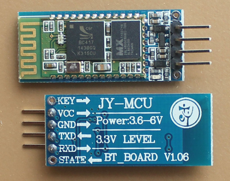
If i can say.. :) only a "little" detail which caught my eyes : the bluetooth module orientation and its clearance are not ideal, especially copper under the antenna. that will reduce range I think..but maybe it works enough like that for your usecase.Keep the good work
-
@sundberg84
I've not read the whole description yet, but looks like a nice project :+1:
If i can say.. :) only a "little" detail which caught my eyes : the bluetooth module orientation and its clearance are not ideal, especially copper under the antenna. that will reduce range I think..but maybe it works enough like that for your usecase.Keep the good work
@scalz thanks for the feedback! Exactly like this I want before 1.0! BT range has not been tested except that it works fine standing next to the node with my phone. I will look some inte that. 👍
-
Very interesting board, I was waiting for you to publish it as I will probably need one :)
Here are my remarks after aquicklook:-
I agree with @scalz about the Bluetooth module. You should turn it 180° to have antenna on the side of the PCB, either antenna outside of the PCB area, or with no copper below and on the sides as far as possible, as visible on the bottom of the module below. Limit of your ground plane should be aligned with the limit of the ground plane on your Bluetooth module.
-
For the leds, why not have jumpers, so it's easy to switch leds on/off if for example you want to make sure everything is fine at the beginning, then want the module to run on batteries for a long time. It's much easier to put/remove jumpers than solder/unsolder leds
-
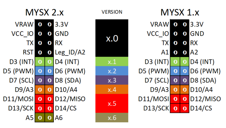
I'll be annoying with this one, but why not make your module connector compatible with MYSX connector, or add a MYSX compatible connector ? Then it would be possible to just plug in your logger in a compatible board, starting with EasyPCB, and you're done.
On your board you would need only a 6pins connector so it would be compatible with versions 1.0 and 2.0 :
VRAW => Not connected, or fed like in "parasite mode" through a switch, or you could even have a 3 positions switch that would instead feed your logging board through the regulator
3.3V => Not connected, this is managed by the board
VCC_IO => this would replace the "5V" connected to the drain of the BSS138 on your schematic (but it sounds like a bad idea to connect it to V+ directly !)
GND => GND
TX/RX => RX/TX (as you're a "child" board)
-
-
Very interesting board, I was waiting for you to publish it as I will probably need one :)
Here are my remarks after aquicklook:-
I agree with @scalz about the Bluetooth module. You should turn it 180° to have antenna on the side of the PCB, either antenna outside of the PCB area, or with no copper below and on the sides as far as possible, as visible on the bottom of the module below. Limit of your ground plane should be aligned with the limit of the ground plane on your Bluetooth module.
-
For the leds, why not have jumpers, so it's easy to switch leds on/off if for example you want to make sure everything is fine at the beginning, then want the module to run on batteries for a long time. It's much easier to put/remove jumpers than solder/unsolder leds
-
I'll be annoying with this one, but why not make your module connector compatible with MYSX connector, or add a MYSX compatible connector ? Then it would be possible to just plug in your logger in a compatible board, starting with EasyPCB, and you're done.
On your board you would need only a 6pins connector so it would be compatible with versions 1.0 and 2.0 :
VRAW => Not connected, or fed like in "parasite mode" through a switch, or you could even have a 3 positions switch that would instead feed your logging board through the regulator
3.3V => Not connected, this is managed by the board
VCC_IO => this would replace the "5V" connected to the drain of the BSS138 on your schematic (but it sounds like a bad idea to connect it to V+ directly !)
GND => GND
TX/RX => RX/TX (as you're a "child" board)
@Nca78 this is gold! Thank you!!
First the easy one - there is a led jumper to be able to turn the on and off. At the moment it's a solder jumper so not possible to change with a switch.
About the Bluetooth - I will change this!
MysX! Offcourse... I will look into this as well for 1.0! Would be so easy! I just need to figure out if it works with all voltage levels...
Thanks!!!
Controller: Proxmox VM - Home Assistant
MySensors GW: Arduino Uno - W5100 Ethernet, Gw Shield Nrf24l01+ 2,4Ghz
MySensors GW: Arduino Uno - Gw Shield RFM69, 433mhz
RFLink GW - Arduino Mega + RFLink Shield, 433mhz -
-
@Nca78 this is gold! Thank you!!
First the easy one - there is a led jumper to be able to turn the on and off. At the moment it's a solder jumper so not possible to change with a switch.
About the Bluetooth - I will change this!
MysX! Offcourse... I will look into this as well for 1.0! Would be so easy! I just need to figure out if it works with all voltage levels...
Thanks!!!
@sundberg84 said in 💬 The Logger Machine - Short and long term serial logging:
First the easy one - there is a led jumper to be able to turn the on and off. At the moment it's a solder jumper so not possible to change with a switch.
Are those the holes on the "top" of the board ? If yes then it's fine I'm not talking about switches but jumpers that you can easily put/remove on 2.54mm spaced pins, like that (random result on aliexpress):
https://fr.aliexpress.com/item/EziUsin-Colorful-Pin-Header-Standard-Computer-Jumper-Blocks-Connector-2-54-mm-3-1-2-Hard/32827199777.html -
@sundberg84 said in 💬 The Logger Machine - Short and long term serial logging:
First the easy one - there is a led jumper to be able to turn the on and off. At the moment it's a solder jumper so not possible to change with a switch.
Are those the holes on the "top" of the board ? If yes then it's fine I'm not talking about switches but jumpers that you can easily put/remove on 2.54mm spaced pins, like that (random result on aliexpress):
https://fr.aliexpress.com/item/EziUsin-Colorful-Pin-Header-Standard-Computer-Jumper-Blocks-Connector-2-54-mm-3-1-2-Hard/32827199777.html@Nca78 this one:
Its solderpads so you have to solder and desolder but I will consider 2.54 spacings for pins.
-
Very interesting board, I was waiting for you to publish it as I will probably need one :)
Here are my remarks after aquicklook:-
I agree with @scalz about the Bluetooth module. You should turn it 180° to have antenna on the side of the PCB, either antenna outside of the PCB area, or with no copper below and on the sides as far as possible, as visible on the bottom of the module below. Limit of your ground plane should be aligned with the limit of the ground plane on your Bluetooth module.
-
For the leds, why not have jumpers, so it's easy to switch leds on/off if for example you want to make sure everything is fine at the beginning, then want the module to run on batteries for a long time. It's much easier to put/remove jumpers than solder/unsolder leds
-
I'll be annoying with this one, but why not make your module connector compatible with MYSX connector, or add a MYSX compatible connector ? Then it would be possible to just plug in your logger in a compatible board, starting with EasyPCB, and you're done.
On your board you would need only a 6pins connector so it would be compatible with versions 1.0 and 2.0 :
VRAW => Not connected, or fed like in "parasite mode" through a switch, or you could even have a 3 positions switch that would instead feed your logging board through the regulator
3.3V => Not connected, this is managed by the board
VCC_IO => this would replace the "5V" connected to the drain of the BSS138 on your schematic (but it sounds like a bad idea to connect it to V+ directly !)
GND => GND
TX/RX => RX/TX (as you're a "child" board)
VRAW => Not connected, or fed like in "parasite mode" through a switch, or you could even have a 3 positions switch that would instead feed your logging board through the regulator
3.3V => Not connected, this is managed by the board
VCC_IO => this would replace the "5V" connected to the drain of the BSS138 on your schematic (but it sounds like a bad idea to connect it to V+ directly !)
GND => GND
TX/RX => RX/TX (as you're a "child" board)Im thinking like this (the main issue is that im feeling im missing 1 ground pin!)
MysX
- VRAW = V+ (or I should replace current volt. reg. to be able to work with 12v according to MysX)
- 3.3V = 3.3V (if you want to parasite power from motherboard)
- VCC_IO = Not connected (because this can be everything from 1.9 to 5V in MySensors world)
- GND = GND
- TX/RX => RX/TX (as you're a "child" board)
- RST = RST
- Leg_ID = Not connected
Second Pinheader
BAT - 2.2-3.3v to booster
GND - GNDController: Proxmox VM - Home Assistant
MySensors GW: Arduino Uno - W5100 Ethernet, Gw Shield Nrf24l01+ 2,4Ghz
MySensors GW: Arduino Uno - Gw Shield RFM69, 433mhz
RFLink GW - Arduino Mega + RFLink Shield, 433mhz -
-
VRAW => Not connected, or fed like in "parasite mode" through a switch, or you could even have a 3 positions switch that would instead feed your logging board through the regulator
3.3V => Not connected, this is managed by the board
VCC_IO => this would replace the "5V" connected to the drain of the BSS138 on your schematic (but it sounds like a bad idea to connect it to V+ directly !)
GND => GND
TX/RX => RX/TX (as you're a "child" board)Im thinking like this (the main issue is that im feeling im missing 1 ground pin!)
MysX
- VRAW = V+ (or I should replace current volt. reg. to be able to work with 12v according to MysX)
- 3.3V = 3.3V (if you want to parasite power from motherboard)
- VCC_IO = Not connected (because this can be everything from 1.9 to 5V in MySensors world)
- GND = GND
- TX/RX => RX/TX (as you're a "child" board)
- RST = RST
- Leg_ID = Not connected
Second Pinheader
BAT - 2.2-3.3v to booster
GND - GND@sundberg84 said in 💬 The Logger Machine - Short and long term serial logging:
Im thinking like this (the main issue is that im feeling im missing 1 ground pin!)
MysX
- VRAW = V+ (or I should replace current volt. reg. to be able to work with 12v according to MysX)
I'm not sure this is the way to go. By default I would use the MySX for the case when logger is auto-powered with batteries so as not to interfere with node, and in case someone wants to power logger from the same power source or parasite power from logger then use a separate header with 3*2 header for power input...:
- one source for batteries: VBAT & GND for stable voltage <6V using XC6206 regulator
- one for power supplies: V+ & GND, 5-12V, using AMS1117 or similar, able to filter a lot of ripple
- one for 2 AA/AAA feeding your step up: Vaa & GND
...and one 1*2 header for power output :
- V3.3 & GND, generated from one of the 3 above sources
Then nothing prevents you to have a jumpers to connect the VRAW pin of the MYSX connector to the different power sources, to be able to feed the board directly from there, but I'm afraid it will get a bit messy :)
- 3.3V = 3.3V (if you want to parasite power from motherboard)
I think it's a bad idea, the 3.3V is supposed to be generated by the "mother" board, and it's not always 3.3V
For example if I have a board powered with a CR2032 it's probably running at 2.8-2.9V, if I connect the MySX connector then you will feed my CR2032 with 3.3V, I predict some bad results :)- VCC_IO = Not connected (because this can be everything from 1.9 to 5V in MySensors world)
To me this is what you should connect to your level converter, because this will be your reference level for "high" voltage on the RX pin.
- RST = RST
Are you sure you want to connect the reset of the node and reset of the logger ?
Maybe it would be useful to be able to send a reset command to the node through the bluetooth link, and in that case to use a separate pin from the atmega on the logger board to control the reset of the child board (in fact, it sounds like a great option :D ) but I'm not sure I want to reset logger when I press reset button on node.Second Pinheader
BAT - 2.2-3.3v to booster
GND - GNDAs explained above I would make the second pin header a bit bigger :D
-
@sundberg84 said in 💬 The Logger Machine - Short and long term serial logging:
Im thinking like this (the main issue is that im feeling im missing 1 ground pin!)
MysX
- VRAW = V+ (or I should replace current volt. reg. to be able to work with 12v according to MysX)
I'm not sure this is the way to go. By default I would use the MySX for the case when logger is auto-powered with batteries so as not to interfere with node, and in case someone wants to power logger from the same power source or parasite power from logger then use a separate header with 3*2 header for power input...:
- one source for batteries: VBAT & GND for stable voltage <6V using XC6206 regulator
- one for power supplies: V+ & GND, 5-12V, using AMS1117 or similar, able to filter a lot of ripple
- one for 2 AA/AAA feeding your step up: Vaa & GND
...and one 1*2 header for power output :
- V3.3 & GND, generated from one of the 3 above sources
Then nothing prevents you to have a jumpers to connect the VRAW pin of the MYSX connector to the different power sources, to be able to feed the board directly from there, but I'm afraid it will get a bit messy :)
- 3.3V = 3.3V (if you want to parasite power from motherboard)
I think it's a bad idea, the 3.3V is supposed to be generated by the "mother" board, and it's not always 3.3V
For example if I have a board powered with a CR2032 it's probably running at 2.8-2.9V, if I connect the MySX connector then you will feed my CR2032 with 3.3V, I predict some bad results :)- VCC_IO = Not connected (because this can be everything from 1.9 to 5V in MySensors world)
To me this is what you should connect to your level converter, because this will be your reference level for "high" voltage on the RX pin.
- RST = RST
Are you sure you want to connect the reset of the node and reset of the logger ?
Maybe it would be useful to be able to send a reset command to the node through the bluetooth link, and in that case to use a separate pin from the atmega on the logger board to control the reset of the child board (in fact, it sounds like a great option :D ) but I'm not sure I want to reset logger when I press reset button on node.Second Pinheader
BAT - 2.2-3.3v to booster
GND - GNDAs explained above I would make the second pin header a bit bigger :D
@Nca78 thanks for your input.. my main concern is that I don't want to many pi headers... Well I now have rev 0.5 on its way so some time to think about it.
-
@sundberg84 said in 💬 The Logger Machine - Short and long term serial logging:
Im thinking like this (the main issue is that im feeling im missing 1 ground pin!)
MysX
- VRAW = V+ (or I should replace current volt. reg. to be able to work with 12v according to MysX)
I'm not sure this is the way to go. By default I would use the MySX for the case when logger is auto-powered with batteries so as not to interfere with node, and in case someone wants to power logger from the same power source or parasite power from logger then use a separate header with 3*2 header for power input...:
- one source for batteries: VBAT & GND for stable voltage <6V using XC6206 regulator
- one for power supplies: V+ & GND, 5-12V, using AMS1117 or similar, able to filter a lot of ripple
- one for 2 AA/AAA feeding your step up: Vaa & GND
...and one 1*2 header for power output :
- V3.3 & GND, generated from one of the 3 above sources
Then nothing prevents you to have a jumpers to connect the VRAW pin of the MYSX connector to the different power sources, to be able to feed the board directly from there, but I'm afraid it will get a bit messy :)
- 3.3V = 3.3V (if you want to parasite power from motherboard)
I think it's a bad idea, the 3.3V is supposed to be generated by the "mother" board, and it's not always 3.3V
For example if I have a board powered with a CR2032 it's probably running at 2.8-2.9V, if I connect the MySX connector then you will feed my CR2032 with 3.3V, I predict some bad results :)- VCC_IO = Not connected (because this can be everything from 1.9 to 5V in MySensors world)
To me this is what you should connect to your level converter, because this will be your reference level for "high" voltage on the RX pin.
- RST = RST
Are you sure you want to connect the reset of the node and reset of the logger ?
Maybe it would be useful to be able to send a reset command to the node through the bluetooth link, and in that case to use a separate pin from the atmega on the logger board to control the reset of the child board (in fact, it sounds like a great option :D ) but I'm not sure I want to reset logger when I press reset button on node.Second Pinheader
BAT - 2.2-3.3v to booster
GND - GNDAs explained above I would make the second pin header a bit bigger :D
- VCC_IO = Not connected (because this can be everything from 1.9 to 5V in MySensors world)
To me this is what you should connect to your level converter, because this will be your reference level for "high" voltage on the RX pin.
Would be great but are you sure this works? I tested this on on a breadboard and since the logger works @ 3.3v I could not provide anything lower than 3.3v. That is why I have the 5v input on the high voltage (because this will be atleast 3.3v when lower voltage is applied). A MysSensors node could work @ 1.9v and provide this through this pin.
Will test some more!
Controller: Proxmox VM - Home Assistant
MySensors GW: Arduino Uno - W5100 Ethernet, Gw Shield Nrf24l01+ 2,4Ghz
MySensors GW: Arduino Uno - Gw Shield RFM69, 433mhz
RFLink GW - Arduino Mega + RFLink Shield, 433mhz -
- VCC_IO = Not connected (because this can be everything from 1.9 to 5V in MySensors world)
To me this is what you should connect to your level converter, because this will be your reference level for "high" voltage on the RX pin.
Would be great but are you sure this works? I tested this on on a breadboard and since the logger works @ 3.3v I could not provide anything lower than 3.3v. That is why I have the 5v input on the high voltage (because this will be atleast 3.3v when lower voltage is applied). A MysSensors node could work @ 1.9v and provide this through this pin.
Will test some more!
@sundberg84 yes I didn't look carefully enough at what this bss138 chip is.
I was about to suggest TXS0108E or TXB0104 but they have the same constraint of having to chose your "high voltage" and "low voltage" sides beforehand.The SX150x chips would do the trick but only the SX1509 is available and in addition to not beeing cheap it's also extremely hard to hand solder :)
[edit]
Found the SN74LVC8T245 also from TI that doesn't have the requirement. Made for 8 bits but works with any input and output voltage level. -
I updated the 3d box. One of the holes for the switches was a bit off and also it was a little tight for the logger itself.
-
Hello Sandberg84, I recently bought the logger and have problem setting up baud rate.
I can connect to BT with my phone just fine, I can get serial output from sensor at specified intervals, but it is all nonprintable characters, alas bad baud rate.
When I connect logger to pc via serial adapter I get no response to AT commands.
Can you show me way to try something?Thanx
@terxw - sure! How do you connect when you wants to set up baud rate. (Picture?)
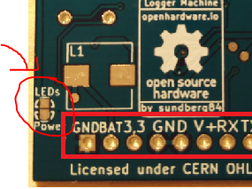
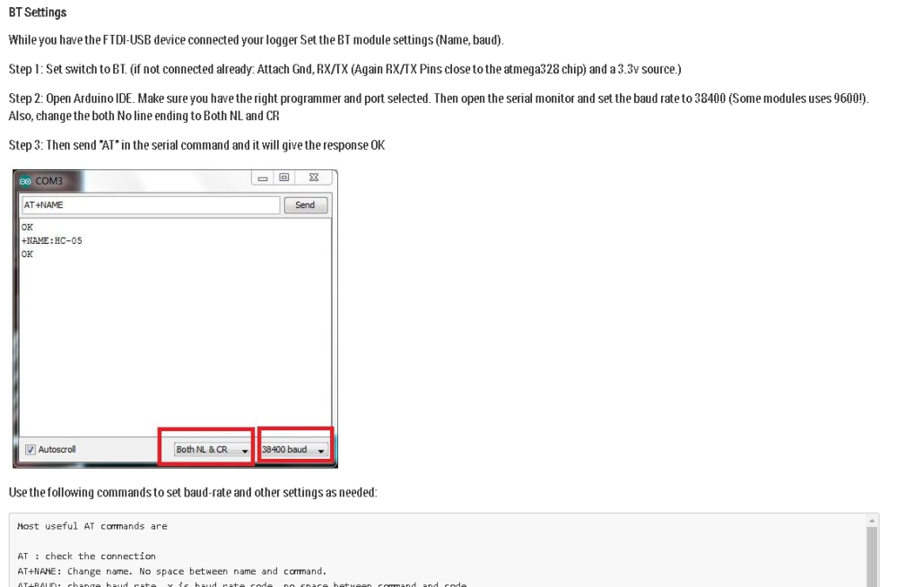
The module i send have 115200 set as for BT. If you have a node with that baud-rate - does it work? Or what does your node have at the moment for baudrate?This is from https://www.openhardware.io/view/532/The-Logger-Machine-Short-and-long-term-serial-logging where i documented the instructions:
 op
op -
OK, couple of good pointers!
I found the atmega RX a TX pins, but cannot get any response in the serial console.
Connectiona are: USB -> USB Serial Converter -> GND, power -> logger & RT/TX -> Tx/RX on atmega on logger.
If I set BR to 11520, I can see on my BT connected phone what I typed in the arduino serial monitor, e.g. if I type "AT" in Arduino serial console with BR 115200 , I can see clear ascii text "AT" on my phone.
If i set BR to 9600 or 38400, I see just scrambled characters or nothing at all.
I tried to put some test serial.println with BR 11520 on new pro mini (3.3V, 8Mhz), when I discovered some interesting problems....
None of my serial/USB converters worked, I tried to guess BR etc. to no avail.
I tried to reupload bootloader with usbasp, with set BR, but could not get clear text serial output form my nodes.... After 5 diferent USB to serial adapters i tried to compile code with arduino IDE instead of platformio, voala, now I could send text from promini with BR 115200 through logger to my phone.So there are couple problems, probably with my toolchain (platformio) - I remembered that I had problems with some new custom boards (NRF24Duino) and serial output which was garbled...
But nevertheless, I cannot change BR of logger, because I am using custom bootloaders with 1 MHz internal oscilator and 4800 BR, I need to set it lower.
What else could I try?
-
OK, couple of good pointers!
I found the atmega RX a TX pins, but cannot get any response in the serial console.
Connectiona are: USB -> USB Serial Converter -> GND, power -> logger & RT/TX -> Tx/RX on atmega on logger.
If I set BR to 11520, I can see on my BT connected phone what I typed in the arduino serial monitor, e.g. if I type "AT" in Arduino serial console with BR 115200 , I can see clear ascii text "AT" on my phone.
If i set BR to 9600 or 38400, I see just scrambled characters or nothing at all.
I tried to put some test serial.println with BR 11520 on new pro mini (3.3V, 8Mhz), when I discovered some interesting problems....
None of my serial/USB converters worked, I tried to guess BR etc. to no avail.
I tried to reupload bootloader with usbasp, with set BR, but could not get clear text serial output form my nodes.... After 5 diferent USB to serial adapters i tried to compile code with arduino IDE instead of platformio, voala, now I could send text from promini with BR 115200 through logger to my phone.So there are couple problems, probably with my toolchain (platformio) - I remembered that I had problems with some new custom boards (NRF24Duino) and serial output which was garbled...
But nevertheless, I cannot change BR of logger, because I am using custom bootloaders with 1 MHz internal oscilator and 4800 BR, I need to set it lower.
What else could I try?
@terxw - ok.
4800 should work just fine.
The command should be AT+BAUD3
I used this link when i designed and wrote this - it has some more in-depth analysis.
https://www.instructables.com/id/AT-command-mode-of-HC-05-Bluetooth-module/What good to know is that if you are the one who bought the module from me just recently from ebay this is tested and verified working by me so we should get this sorted!!
Can you post a picture on how it looks (connections) when you try to change baud-rate?
-
@terxw - sorry, the manual is wrong and unclear here - when you talk to the bluetooth module you should not connect to the programming pins. they are only for programming atmega chip. Must be a copy/paste error when i wrote the manual i think. Looking at the schematics RX goes only from that programming pin to the atmega and not bt module. TX has a input protection diode as well, so you need to swap that one to.
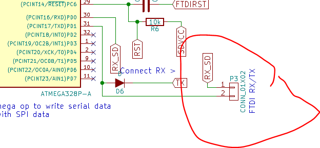
As you see in the image, RX and TX from that programming point is only connected to atmega chip. Try connecting them to ordinary input. In worst case scenario, the diodes are making the serial communication fail at the baud rate you are testing... (should work with 115200 since thats what i set it to) but worst case scenario, solder wires to BT module and test.
Also dont power it using BAT (it goes through a dc/dc booster if you do). Try a regulated 3.3v power source and input on 3.3v pin.
Also, change the both No line ending to Both NL and CR
Edit: I will be home on thursday, traveling at work, but I have a identical module i build the same time as yours I can test on, if you dont want to solder around and mess the module up.