Solar Powered Mini-Weather Station
-
I remember having one of those beginner electronic kits when I was young and I was so excited the day I listened to our local radio station with the crystal radio I built with the kit. Decades later now, I’m finally re-living my childhood with MySensors. It was fun back then and it is again. I’m definitely a noob at this, I’m not an electrical engineer, but I have a knack for adopting the work of others and applying it to my own world. So to start off this project, I first need to thank Hek and all the other more knowledgeable and capable people that have developed what I use. This is really fun.
Many of the MySensor projects are weather related, and this one is no different. I figured if I can do simple sensoring, I’ll learn the basics necessary to move on to the more advanced technologies. I am so new to this that I had to buy a soldering iron and learn how to use it. Research and practice are all part of this, and to that end I’ve already built my Vera Serial Gateway and my first sensor – a battery powered temperature and humidity sensor that sits in my kitchen. This project is my attempt to extend that knowledge to a mini-weather station that operates outdoors.
My requirements were simple: 1) Build an inexpensive outdoor weather station, 2) Use the low-power battery features found in the MySensors Arduino libraries, and 3) Integrate it into my Vera home automation environment. I first put a list together of the components I could put into the weather station to comply with my first requirement. The list goes as follows (I’ve been using eBay, usually in lots of 10):
- Arduino Pro Mini 3.3v 8MHz processor @ $2.50 USD
- NRF24L01+ Transceiver @ $0.90
- DHT22 Humidity & Temperature sensor @ $3.50
- BMP180 Barometric Pressure sensor @ $1.70
- BH1750FVI Ambient Light Intensity sensor @ $2.10
- Rain Sensor Module @ $1.30
The weather station components total $12.00 USD without power and a project box. Humidity was actually the most expensive piece given that the BMP180 also provides temperature. The DHT11 is less costly, but doesn’t really provide the range for an outdoor sensor. I did look at adding some other sensors. For another $10 I could add Ultraviolet sensing, for $25 I could put in a lightning sensor, $45 for wind speed, and even more for wind direction and a rain gauge. All those others would be great to have, but too costly for this project. I might try my hand at building an anemometer to add to this, and I see others are working on rain gauges, but those are projects for another day.
I then needed power and an enclosure. I could have put them in a large waterproof box ($2.70), a three cell AA battery holder ($0.80), and some DuraRabbit batteries for a year ($3.00). For an additional $6.50, I was ready to go. Oh, did I mention I was lazy? I don’t really want to swap out the batteries every six months (or less), so I decided to splurge and go the solar route.
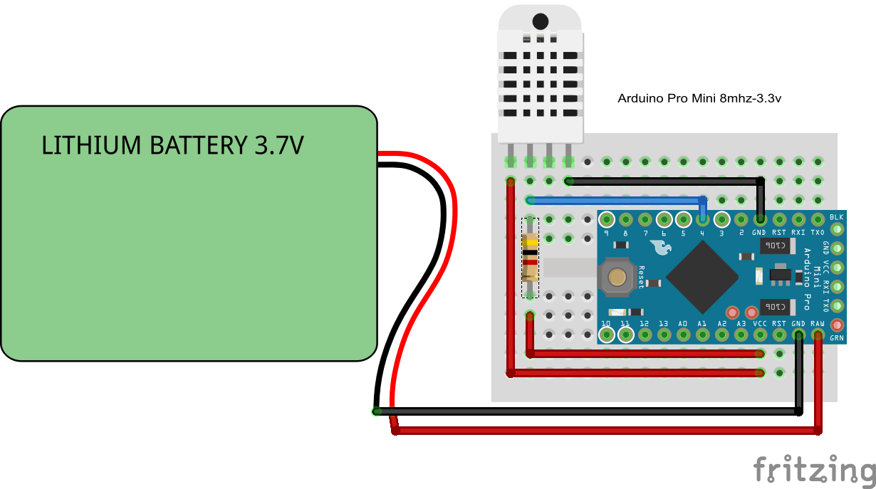
Add a 5v solar panel ($3.35) and a 3.7v 1000mAh li-ion battery ($3.75), and some way to charge the battery (Micro USB 5V 1A 18650 Lithium Battery Charger Board With Protection Module @ $0.75) instead, and my total project cost went to $22.55. Of that, over $10 went to the box, the panel and charger, and the battery. Then I found this.
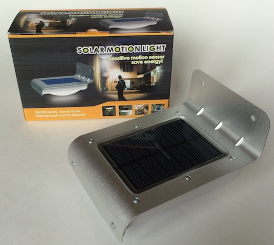
It’s entitled “16 LED Solar Power Motion Sensor Security Lamp Outdoor Waterproof Light” (http://www.ebay.com/itm/271693521438) that you can get for $9.00. I now had a $21 weather station ready to be built.
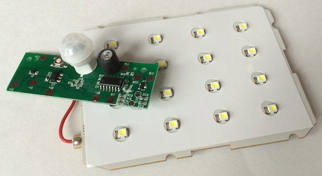
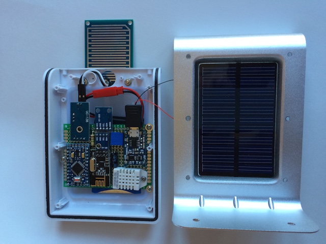
Taking apart the lamp, I removed the LED panel (worth at least $2.00) and the control board (this has some good stuff on it like a PIR, a light sensor, and the battery charging circuitry, but its use is well beyond my skills), and put them away for another project.
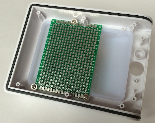
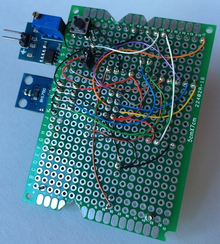
I took a 5x7cm fiberglass PCB and cut a few notches in the sides so the board would fit within the new project case. Using the mounting screws that held the LED board down, I had a good way to affix the circuit board to the case.
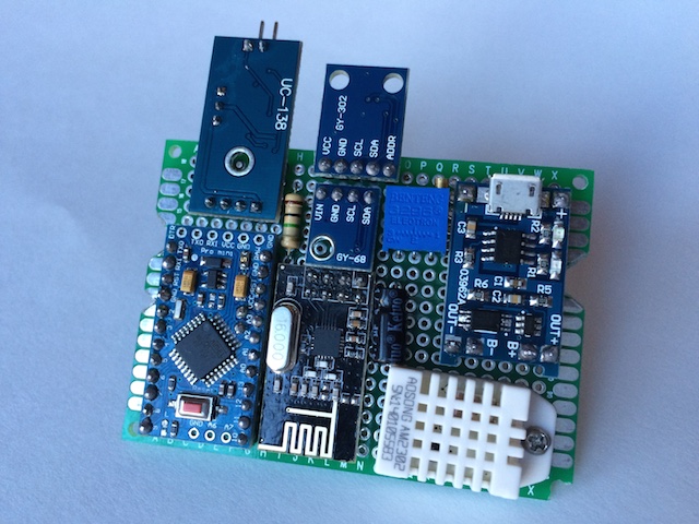
Next, I laid out how to cram all these components (including the R1 at 1MΩ & R2 [a 3296W potentiometer 500kΩ] resistors for the voltage divider to track battery voltage and the capacitor for the radio) into the enclosure. I ended up with a tight fit, but very manageable.
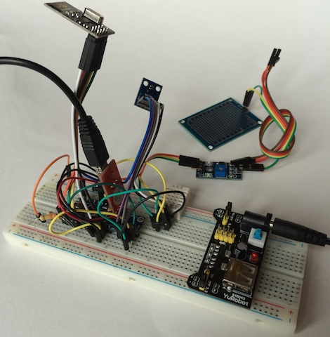
One rule I’ve learned is to always breadboard all the components and measure the performance. This is where I check the current being used during the sleep mode and I get to test my preliminary sketch. It is a very good use of my time as I’ve come upon some bad components in what little of this that I’ve done and this is where they can be identified.
When I started learning the how-to’s of this hobby, I bought all sorts of stuff. One of the first purchases was one of those boxes of 22-gauge wire. The first one was stranded, so then I had to try solid to see if it was any easier to work with. It is, but is still huge compared to what is needed for these low-current projects. I found some old computer cables that had 26-gauge stranded in them. Better, but not what I wanted. Finally I came upon some discussions of wire-wrapping. I now use 30-gauge solid, first installed with a wire-wrapping tool (what a scam and I even found a cheap one for less than $20.)
I decided to add two additional features after breadboarding the circuit. First, I wanted a reset button that could be reached without taking the case apart. At times I’ve found my sensors need a quick reboot. A switch was added to the underside of the PCB and a hole in the underside of the case will allow me to use a paperclip to do a reset.
The other feature I added was a jumper that I could use to enable or disable the rain sensor if I chose to at a later date. For some reason it adds a significant load to the circuit. Without the rain sensor enabled, the circuit idles at 270 µA. With it I get 0.98 mA during the gw.sleep command. If I was smart enough, I’m sure I could get that down, but that’s still something to be learned. The underside, as usual, looked like spaghetti.
After a little bit of solder (I’m actually getting pretty good at that part), I have a fully functional circuit. Since the Li-Ion charging component takes a micro-USB connection, I charged the battery fully and then adjusted the pot to get the AO output to be right at 1023. For this setup my voltmeter showed the battery at 4.15v. I then needed to calibrate the circuit to get to the lower end of the acceptable voltage range. I’ve seen several different numbers for the bottom end of a 3.7v li-ion battery, some down to 2.7v. I chose 3.3v as my lowest acceptable value and proceeded to drain the battery (those LED arrays came in handy after all) down to 3.0v to see what the circuit value came out to be. For my setup, at 3.3v I was getting a value of 800 from pin A0. I updated the sketch so that it would be equal to 0% (hopefully it never gets there.)
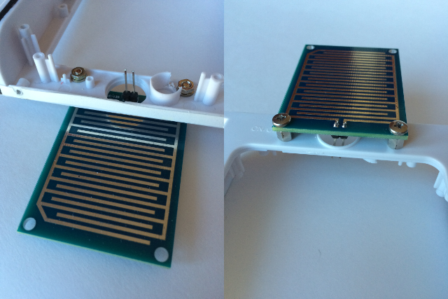
I had one addition to make to the project case. The rain sensor has a board that needs to be exposed to the elements. I drilled a couple of holes in the front end of the case and found some connectors that would work. The hole in the original case for the PIR sensor was a great opening to pass the cable through. The results actually look pretty good, if I can say so myself.
A couple of last minute touch-ups: two holes in the lens of the light, one for the reset button and one for the pot that adjusts the sensitivity of the rain sensor. I also take off any LEDs on the circuit, even LED13 on the Arduino. Every little bit helps. Does an LED actually illuminate if no one is there to see it? The final product came out nice.
One last upload of the final sketch. I took all the weather prediction logic out of the pressure sketch to save room for the other components. The SLEEP_TIME parameter is set for once every minute. I also added some lines of code to have the sensor update all measurements once an hour. I really like the ability to see when a measurement was last updated. That’s a nice touch to the MySensors library.
    #include <SPI.h>
    #include <MySensor.h>
    #include <DHT.h>
    #include <BH1750.h>
    #include <Wire.h>
    #include <Adafruit_BMP085.h>

    #define CHILD_ID_HUM 0
    #define CHILD_ID_TEMP 1
    #define CHILD_ID_LIGHT 2
    #define CHILD_ID_BARO 3
    #define CHILD_ID_BTEMP 4
    #define CHILD_ID_RAIN 5

    #define DIGITAL_INPUT_RAIN_SENSOR 3
    #define HUMIDITY_SENSOR_DIGITAL_PIN 4
    #define INTERRUPT DIGITAL_INPUT_RAIN_SENSOR-2

    boolean metric = false;
    int altitude = 221; // 741 feet above sealevel
    float lastBmpTemp = -1;
    float lastPressure = -1;
    float lastHum = -1;
    float lastTemp = -1;
    int BATTERY_SENSE_PIN = A0;
    int lastRainValue = -1;
    int lastBatteryPcnt = 0;
    int updateAll = 60;
    int updateCount = 0;
    uint16_t lastLux;
    unsigned long SLEEP_TIME = 60000;
    int batteryBasement = 800;
    float batteryConstant = 100.0 / (1023 - batteryBasement);

    Adafruit_BMP085 bmp = Adafruit_BMP085();
    BH1750 lightSensor;
    DHT dht;
    MySensor gw;

    MyMessage msgHum(CHILD_ID_HUM, V_HUM);
    MyMessage msgTemp(CHILD_ID_TEMP, V_TEMP);
    MyMessage msgLux(CHILD_ID_LIGHT, V_LIGHT_LEVEL);
    MyMessage msgBtemp(CHILD_ID_BTEMP, V_TEMP);
    MyMessage msgPressure(CHILD_ID_BARO, V_PRESSURE);
    MyMessage msgRain(CHILD_ID_RAIN, V_TRIPPED);

    void setup()
    {
      analogReference(INTERNAL);
      gw.begin();
      dht.setup(HUMIDITY_SENSOR_DIGITAL_PIN);
      bmp.begin();
      gw.sendSketchInfo("Weather Sensor", "1.0");
      gw.present(CHILD_ID_HUM, S_HUM);
      gw.present(CHILD_ID_TEMP, S_TEMP);
      gw.present(CHILD_ID_LIGHT, S_LIGHT_LEVEL);
      gw.present(CHILD_ID_BARO, S_BARO);
      gw.present(CHILD_ID_BTEMP, S_TEMP);
      gw.present(CHILD_ID_RAIN, S_MOTION);
      pinMode(DIGITAL_INPUT_RAIN_SENSOR, INPUT);
      lightSensor.begin();
      metric = gw.getConfig().isMetric;
    }

    void loop()
    {
      updateCount += 1;
      if (updateCount == updateAll) {
        lastTemp = -1;
        lastHum = -1;
        lastLux = -1;
        lastBmpTemp = -1;
        lastPressure = -1;
        lastRainValue = -1;
        lastBatteryPcnt = -1;
        updateCount = 0;
      }
      delay(dht.getMinimumSamplingPeriod());
      float temperature = dht.getTemperature();
      if (isnan(temperature)) {
          lastTemp = -1;
      } else if (temperature != lastTemp) {
        lastTemp = temperature;
        if (!metric) {
          temperature = temperature * 1.8 + 32.0;
        }
        gw.send(msgTemp.set(temperature, 1));
      }
      float humidity = dht.getHumidity();
      if (isnan(humidity)) {
          lastHum = -1;
      } else if (humidity != lastHum) {
          lastHum = humidity;
          gw.send(msgHum.set(humidity, 1));
      }
      uint16_t lux = lightSensor.readLightLevel();
      if (lux != lastLux) {
          gw.send(msgLux.set(lux));
          lastLux = lux;
      }
      float pressure = bmp.readSealevelPressure(altitude) * 0.01;
      float bmptemp = bmp.readTemperature();
      if (!metric) {
        bmptemp = bmptemp * 1.8 + 32.0;
      }
      if (bmptemp != lastBmpTemp) {
        gw.send(msgBtemp.set(bmptemp,1));
        lastBmpTemp = bmptemp;
      }
      if (pressure != lastPressure) {
        gw.send(msgPressure.set(pressure, 0));
        lastPressure = pressure;
      }
      int rainValue = digitalRead(DIGITAL_INPUT_RAIN_SENSOR);
      if (rainValue != lastRainValue) {
        gw.send(msgRain.set(rainValue==0?1:0));
        lastRainValue = rainValue;
      }
      int sensorValue = analogRead(BATTERY_SENSE_PIN);
      int batteryPcnt = (sensorValue - batteryBasement) * batteryConstant;
      if (lastBatteryPcnt != batteryPcnt) {
        gw.sendBatteryLevel(batteryPcnt);
        lastBatteryPcnt = batteryPcnt;
     }
      gw.sleep(SLEEP_TIME);
    }
Then a test to make sure it’s dumping out its results as it should
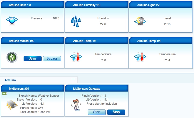
    sensor started, id 1
    send: 1-1-0-0 s=255,c=0,t=17,pt=0,l=5,st=ok:1.4.1
    send: 1-1-0-0 s=255,c=3,t=6,pt=1,l=1,st=ok:0
    read: 0-0-1 s=255,c=3,t=6,pt=0,l=1:I
    send: 1-1-0-0 s=255,c=3,t=11,pt=0,l=14,st=ok:Weather Sensor
    send: 1-1-0-0 s=255,c=3,t=12,pt=0,l=3,st=ok:1.0
    send: 1-1-0-0 s=0,c=0,t=7,pt=0,l=5,st=ok:1.4.1
    send: 1-1-0-0 s=1,c=0,t=6,pt=0,l=5,st=ok:1.4.1
    send: 1-1-0-0 s=2,c=0,t=16,pt=0,l=5,st=ok:1.4.1
    send: 1-1-0-0 s=3,c=0,t=8,pt=0,l=5,st=ok:1.4.1
    send: 1-1-0-0 s=4,c=0,t=6,pt=0,l=5,st=ok:1.4.1
    send: 1-1-0-0 s=5,c=0,t=1,pt=0,l=5,st=ok:1.4.1
    send: 1-1-0-0 s=1,c=1,t=0,pt=7,l=5,st=ok:80.8
    send: 1-1-0-0 s=0,c=1,t=1,pt=7,l=5,st=ok:28.2
    send: 1-1-0-0 s=2,c=1,t=23,pt=3,l=2,st=ok:83
    send: 1-1-0-0 s=4,c=1,t=0,pt=7,l=5,st=ok:80.6
    send: 1-1-0-0 s=3,c=1,t=4,pt=7,l=5,st=ok:1020
    send: 1-1-0-0 s=5,c=1,t=16,pt=2,l=2,st=ok:0
    send: 1-1-0-0 s=255,c=3,t=0,pt=1,l=1,st=ok:91
Finally, we then go to Vera and make sure she’s happy.
This has been a great learning experience for me as it’s my first documented project. I made a bunch of mistakes in between most of the steps you see here. I’ve practiced my soldering techniques for many, many hours. One battery went bye-bye when I didn’t notice the leads had crossed. The smoke was a real good indicator that I’d messed up. I’ve ruined my fair share of components, but I chalk it all up to experience and don’t dwell on them. This hobby is a lot less expensive than golf or fishing, even with my mistakes. I look forward to bigger and better as I continue learn. Thanks again, Hek. This is a hobby that I truly enjoy.
@Salmoides said:
Then I found this.
It’s entitled “16 LED Solar Power Motion Sensor Security Lamp Outdoor Waterproof Light” (http://www.ebay.com/itm/271693521438) that you can get for $9.00. I now had a $21 weather station ready to be built.
Taking apart the lamp, I removed the LED panel (worth at least $2.00) and the control board (this has some good stuff on it like a PIR, a light sensor, and the battery charging circuitry, but its use is well beyond my skills), and put them away for another project.
@Salmoides I mesure less than 1 V at the solar panel wires, which cannot power up the regulator for the arduino.
Do you have the same mesure ?
z-wave - Vera -> Domoticz
rfx - Domoticz <- MyDomoAtHome <- Imperihome
mysensors -> mysensors-gw -> Domoticz -
@Salmoides said:
Then I found this.
It’s entitled “16 LED Solar Power Motion Sensor Security Lamp Outdoor Waterproof Light” (http://www.ebay.com/itm/271693521438) that you can get for $9.00. I now had a $21 weather station ready to be built.
Taking apart the lamp, I removed the LED panel (worth at least $2.00) and the control board (this has some good stuff on it like a PIR, a light sensor, and the battery charging circuitry, but its use is well beyond my skills), and put them away for another project.
@Salmoides I mesure less than 1 V at the solar panel wires, which cannot power up the regulator for the arduino.
Do you have the same mesure ?
@epierre said:
@ mesure less than 1 V at the solar panel wires, which cannot power up the regulator for the arduino.
Do you have the same mesure ?
I have a couple of these units as well and just checked one. It's a cloudy day, but under a bright light it reported 4.3V at the solar panel wires. You might have a bad unit.
Cheers
Al -
@Dwalt Thanks for info but the slant I get from you is this is the old way and now it is just plain soldering.
I also see wire size is an issue.@5546dug I am using wire wrap as well (well, I am old...). The upside of wirewrap is that it does not require electricity, very zen like, you can't make fatal mistakes and you can rescue or replace an arduino without a reflow station. the downside is that there is a limit to the currents (its not bad, but don't try to wire 220v, 3A using wire wrap...), there is a limit to the amount of wires that go to the same post and at times it is slower than soldering (for someone who is practiced). it is very very good for prototyping.
-
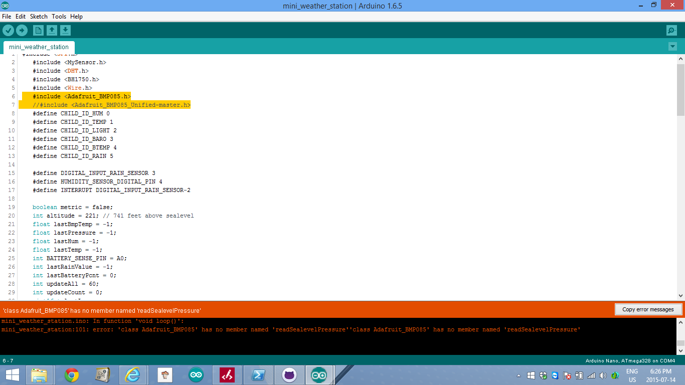
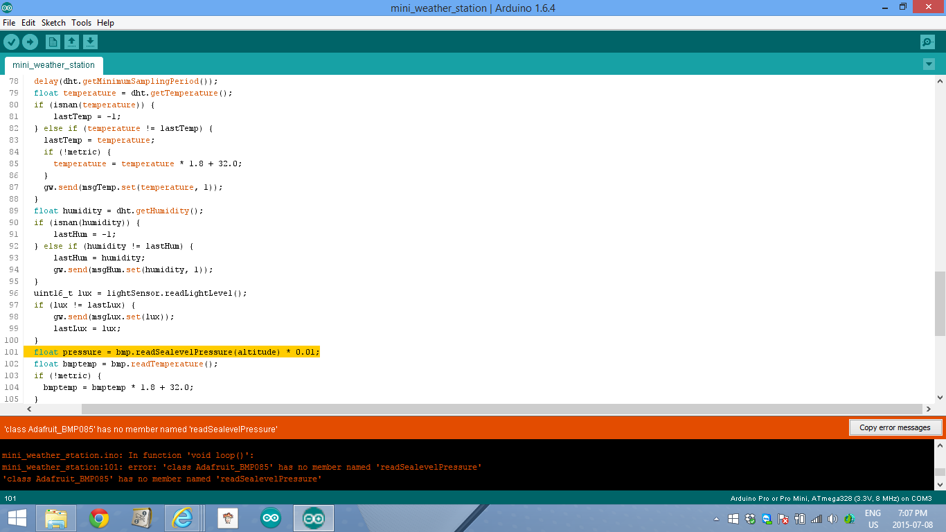
@Salmoides I have tried compiling this code you supplied in the thread prior to uploading to the promini, but it has an issue with the bmp180 code , it cannot read the sea level pressure. I see you set your altitude at 221 meters but I am not able to comprehend the error code on line 101.
enclosed is the screen shot of the issue.
I use ver 1.4 and lib 1.4 -
It's defined in the Adafruit_BMP085 library .cpp file. Did you include the library?
-
I used the supplied code from @Salmoides first reply in this thread.
-
Edit
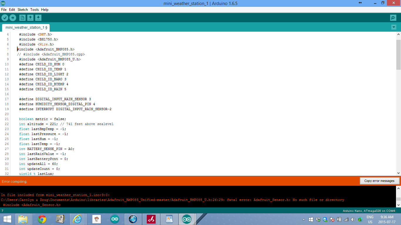
@Pieter-Jan-Stiers , I have tried various combinations of the " include " line in the setup for BMP085 sensor part and it will not compile.
I tried adding the file Adafruit_BMP085_Unified-master.h but the sketch said no such file existed.
However I did download and extract from github and put it in the file ....users/documents/arduino/libraries, I see it in the IDE but that is all
see screen shot at the moment I have it commented out and sketch still does not find read SealevelPressureAny ideas? As I said I am using the sketch from the first post in this thread from @Salmoides
Do I need to create in setup the line
include <Adafruit_BMP085.cpp>
-
Did you close & reopened Arduino IDE after you placed the new library?
-
You can also try it via the menu 'Sketch -> Import Library ... '
Also make sure you are method readSeaLevelPressure is spelled exactly like it is defined in the .h file...
-
@rvendrame I seem to beat a loss as to what to do next
I tried putting the file thru the >file import method and still I get error messages saying cant compile as above.
When I include the unified file there are additional errors all above my paygrade.
I have messed with the line readSealevelPressure<altitude> and the include lines but get nowhere.
I think there is reference to this in original .cpp file but # including this is also errors.
I have remane the files after saving and rebooted ide a few times ...no luck.a
Any ideas or is the file from @Salmoides not compatable anymore? -
How is your 'Sketchbook location' defined? (in "preferences...") Looking into the error message, it looks you are mixing windows slash "\" and unix slash "/" ...
-
After consultation in the troubleshooting category, I downloaded afresh copy of Adafruit-BMP085-library into my arduino library overwriting what was there and now code compiles.
So on to uploading the code to promini and see what the next issue might/will be. -
I remember having one of those beginner electronic kits when I was young and I was so excited the day I listened to our local radio station with the crystal radio I built with the kit. Decades later now, I’m finally re-living my childhood with MySensors. It was fun back then and it is again. I’m definitely a noob at this, I’m not an electrical engineer, but I have a knack for adopting the work of others and applying it to my own world. So to start off this project, I first need to thank Hek and all the other more knowledgeable and capable people that have developed what I use. This is really fun.
Many of the MySensor projects are weather related, and this one is no different. I figured if I can do simple sensoring, I’ll learn the basics necessary to move on to the more advanced technologies. I am so new to this that I had to buy a soldering iron and learn how to use it. Research and practice are all part of this, and to that end I’ve already built my Vera Serial Gateway and my first sensor – a battery powered temperature and humidity sensor that sits in my kitchen. This project is my attempt to extend that knowledge to a mini-weather station that operates outdoors.
My requirements were simple: 1) Build an inexpensive outdoor weather station, 2) Use the low-power battery features found in the MySensors Arduino libraries, and 3) Integrate it into my Vera home automation environment. I first put a list together of the components I could put into the weather station to comply with my first requirement. The list goes as follows (I’ve been using eBay, usually in lots of 10):
- Arduino Pro Mini 3.3v 8MHz processor @ $2.50 USD
- NRF24L01+ Transceiver @ $0.90
- DHT22 Humidity & Temperature sensor @ $3.50
- BMP180 Barometric Pressure sensor @ $1.70
- BH1750FVI Ambient Light Intensity sensor @ $2.10
- Rain Sensor Module @ $1.30
The weather station components total $12.00 USD without power and a project box. Humidity was actually the most expensive piece given that the BMP180 also provides temperature. The DHT11 is less costly, but doesn’t really provide the range for an outdoor sensor. I did look at adding some other sensors. For another $10 I could add Ultraviolet sensing, for $25 I could put in a lightning sensor, $45 for wind speed, and even more for wind direction and a rain gauge. All those others would be great to have, but too costly for this project. I might try my hand at building an anemometer to add to this, and I see others are working on rain gauges, but those are projects for another day.
I then needed power and an enclosure. I could have put them in a large waterproof box ($2.70), a three cell AA battery holder ($0.80), and some DuraRabbit batteries for a year ($3.00). For an additional $6.50, I was ready to go. Oh, did I mention I was lazy? I don’t really want to swap out the batteries every six months (or less), so I decided to splurge and go the solar route.
Add a 5v solar panel ($3.35) and a 3.7v 1000mAh li-ion battery ($3.75), and some way to charge the battery (Micro USB 5V 1A 18650 Lithium Battery Charger Board With Protection Module @ $0.75) instead, and my total project cost went to $22.55. Of that, over $10 went to the box, the panel and charger, and the battery. Then I found this.
It’s entitled “16 LED Solar Power Motion Sensor Security Lamp Outdoor Waterproof Light” (http://www.ebay.com/itm/271693521438) that you can get for $9.00. I now had a $21 weather station ready to be built.
Taking apart the lamp, I removed the LED panel (worth at least $2.00) and the control board (this has some good stuff on it like a PIR, a light sensor, and the battery charging circuitry, but its use is well beyond my skills), and put them away for another project.
I took a 5x7cm fiberglass PCB and cut a few notches in the sides so the board would fit within the new project case. Using the mounting screws that held the LED board down, I had a good way to affix the circuit board to the case.
Next, I laid out how to cram all these components (including the R1 at 1MΩ & R2 [a 3296W potentiometer 500kΩ] resistors for the voltage divider to track battery voltage and the capacitor for the radio) into the enclosure. I ended up with a tight fit, but very manageable.
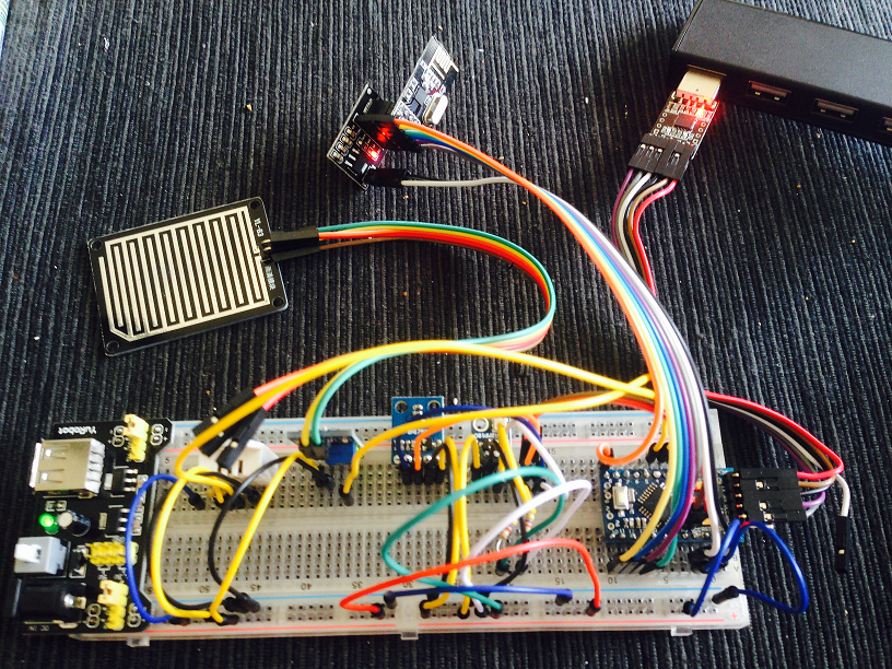
One rule I’ve learned is to always breadboard all the components and measure the performance. This is where I check the current being used during the sleep mode and I get to test my preliminary sketch. It is a very good use of my time as I’ve come upon some bad components in what little of this that I’ve done and this is where they can be identified.
When I started learning the how-to’s of this hobby, I bought all sorts of stuff. One of the first purchases was one of those boxes of 22-gauge wire. The first one was stranded, so then I had to try solid to see if it was any easier to work with. It is, but is still huge compared to what is needed for these low-current projects. I found some old computer cables that had 26-gauge stranded in them. Better, but not what I wanted. Finally I came upon some discussions of wire-wrapping. I now use 30-gauge solid, first installed with a wire-wrapping tool (what a scam and I even found a cheap one for less than $20.)
I decided to add two additional features after breadboarding the circuit. First, I wanted a reset button that could be reached without taking the case apart. At times I’ve found my sensors need a quick reboot. A switch was added to the underside of the PCB and a hole in the underside of the case will allow me to use a paperclip to do a reset.
The other feature I added was a jumper that I could use to enable or disable the rain sensor if I chose to at a later date. For some reason it adds a significant load to the circuit. Without the rain sensor enabled, the circuit idles at 270 µA. With it I get 0.98 mA during the gw.sleep command. If I was smart enough, I’m sure I could get that down, but that’s still something to be learned. The underside, as usual, looked like spaghetti.
After a little bit of solder (I’m actually getting pretty good at that part), I have a fully functional circuit. Since the Li-Ion charging component takes a micro-USB connection, I charged the battery fully and then adjusted the pot to get the AO output to be right at 1023. For this setup my voltmeter showed the battery at 4.15v. I then needed to calibrate the circuit to get to the lower end of the acceptable voltage range. I’ve seen several different numbers for the bottom end of a 3.7v li-ion battery, some down to 2.7v. I chose 3.3v as my lowest acceptable value and proceeded to drain the battery (those LED arrays came in handy after all) down to 3.0v to see what the circuit value came out to be. For my setup, at 3.3v I was getting a value of 800 from pin A0. I updated the sketch so that it would be equal to 0% (hopefully it never gets there.)
I had one addition to make to the project case. The rain sensor has a board that needs to be exposed to the elements. I drilled a couple of holes in the front end of the case and found some connectors that would work. The hole in the original case for the PIR sensor was a great opening to pass the cable through. The results actually look pretty good, if I can say so myself.
A couple of last minute touch-ups: two holes in the lens of the light, one for the reset button and one for the pot that adjusts the sensitivity of the rain sensor. I also take off any LEDs on the circuit, even LED13 on the Arduino. Every little bit helps. Does an LED actually illuminate if no one is there to see it? The final product came out nice.
One last upload of the final sketch. I took all the weather prediction logic out of the pressure sketch to save room for the other components. The SLEEP_TIME parameter is set for once every minute. I also added some lines of code to have the sensor update all measurements once an hour. I really like the ability to see when a measurement was last updated. That’s a nice touch to the MySensors library.
    #include <SPI.h>
    #include <MySensor.h>
    #include <DHT.h>
    #include <BH1750.h>
    #include <Wire.h>
    #include <Adafruit_BMP085.h>

    #define CHILD_ID_HUM 0
    #define CHILD_ID_TEMP 1
    #define CHILD_ID_LIGHT 2
    #define CHILD_ID_BARO 3
    #define CHILD_ID_BTEMP 4
    #define CHILD_ID_RAIN 5

    #define DIGITAL_INPUT_RAIN_SENSOR 3
    #define HUMIDITY_SENSOR_DIGITAL_PIN 4
    #define INTERRUPT DIGITAL_INPUT_RAIN_SENSOR-2

    boolean metric = false;
    int altitude = 221; // 741 feet above sealevel
    float lastBmpTemp = -1;
    float lastPressure = -1;
    float lastHum = -1;
    float lastTemp = -1;
    int BATTERY_SENSE_PIN = A0;
    int lastRainValue = -1;
    int lastBatteryPcnt = 0;
    int updateAll = 60;
    int updateCount = 0;
    uint16_t lastLux;
    unsigned long SLEEP_TIME = 60000;
    int batteryBasement = 800;
    float batteryConstant = 100.0 / (1023 - batteryBasement);

    Adafruit_BMP085 bmp = Adafruit_BMP085();
    BH1750 lightSensor;
    DHT dht;
    MySensor gw;

    MyMessage msgHum(CHILD_ID_HUM, V_HUM);
    MyMessage msgTemp(CHILD_ID_TEMP, V_TEMP);
    MyMessage msgLux(CHILD_ID_LIGHT, V_LIGHT_LEVEL);
    MyMessage msgBtemp(CHILD_ID_BTEMP, V_TEMP);
    MyMessage msgPressure(CHILD_ID_BARO, V_PRESSURE);
    MyMessage msgRain(CHILD_ID_RAIN, V_TRIPPED);

    void setup()
    {
      analogReference(INTERNAL);
      gw.begin();
      dht.setup(HUMIDITY_SENSOR_DIGITAL_PIN);
      bmp.begin();
      gw.sendSketchInfo("Weather Sensor", "1.0");
      gw.present(CHILD_ID_HUM, S_HUM);
      gw.present(CHILD_ID_TEMP, S_TEMP);
      gw.present(CHILD_ID_LIGHT, S_LIGHT_LEVEL);
      gw.present(CHILD_ID_BARO, S_BARO);
      gw.present(CHILD_ID_BTEMP, S_TEMP);
      gw.present(CHILD_ID_RAIN, S_MOTION);
      pinMode(DIGITAL_INPUT_RAIN_SENSOR, INPUT);
      lightSensor.begin();
      metric = gw.getConfig().isMetric;
    }

    void loop()
    {
      updateCount += 1;
      if (updateCount == updateAll) {
        lastTemp = -1;
        lastHum = -1;
        lastLux = -1;
        lastBmpTemp = -1;
        lastPressure = -1;
        lastRainValue = -1;
        lastBatteryPcnt = -1;
        updateCount = 0;
      }
      delay(dht.getMinimumSamplingPeriod());
      float temperature = dht.getTemperature();
      if (isnan(temperature)) {
          lastTemp = -1;
      } else if (temperature != lastTemp) {
        lastTemp = temperature;
        if (!metric) {
          temperature = temperature * 1.8 + 32.0;
        }
        gw.send(msgTemp.set(temperature, 1));
      }
      float humidity = dht.getHumidity();
      if (isnan(humidity)) {
          lastHum = -1;
      } else if (humidity != lastHum) {
          lastHum = humidity;
          gw.send(msgHum.set(humidity, 1));
      }
      uint16_t lux = lightSensor.readLightLevel();
      if (lux != lastLux) {
          gw.send(msgLux.set(lux));
          lastLux = lux;
      }
      float pressure = bmp.readSealevelPressure(altitude) * 0.01;
      float bmptemp = bmp.readTemperature();
      if (!metric) {
        bmptemp = bmptemp * 1.8 + 32.0;
      }
      if (bmptemp != lastBmpTemp) {
        gw.send(msgBtemp.set(bmptemp,1));
        lastBmpTemp = bmptemp;
      }
      if (pressure != lastPressure) {
        gw.send(msgPressure.set(pressure, 0));
        lastPressure = pressure;
      }
      int rainValue = digitalRead(DIGITAL_INPUT_RAIN_SENSOR);
      if (rainValue != lastRainValue) {
        gw.send(msgRain.set(rainValue==0?1:0));
        lastRainValue = rainValue;
      }
      int sensorValue = analogRead(BATTERY_SENSE_PIN);
      int batteryPcnt = (sensorValue - batteryBasement) * batteryConstant;
      if (lastBatteryPcnt != batteryPcnt) {
        gw.sendBatteryLevel(batteryPcnt);
        lastBatteryPcnt = batteryPcnt;
     }
      gw.sleep(SLEEP_TIME);
    }
Then a test to make sure it’s dumping out its results as it should
    sensor started, id 1
    send: 1-1-0-0 s=255,c=0,t=17,pt=0,l=5,st=ok:1.4.1
    send: 1-1-0-0 s=255,c=3,t=6,pt=1,l=1,st=ok:0
    read: 0-0-1 s=255,c=3,t=6,pt=0,l=1:I
    send: 1-1-0-0 s=255,c=3,t=11,pt=0,l=14,st=ok:Weather Sensor
    send: 1-1-0-0 s=255,c=3,t=12,pt=0,l=3,st=ok:1.0
    send: 1-1-0-0 s=0,c=0,t=7,pt=0,l=5,st=ok:1.4.1
    send: 1-1-0-0 s=1,c=0,t=6,pt=0,l=5,st=ok:1.4.1
    send: 1-1-0-0 s=2,c=0,t=16,pt=0,l=5,st=ok:1.4.1
    send: 1-1-0-0 s=3,c=0,t=8,pt=0,l=5,st=ok:1.4.1
    send: 1-1-0-0 s=4,c=0,t=6,pt=0,l=5,st=ok:1.4.1
    send: 1-1-0-0 s=5,c=0,t=1,pt=0,l=5,st=ok:1.4.1
    send: 1-1-0-0 s=1,c=1,t=0,pt=7,l=5,st=ok:80.8
    send: 1-1-0-0 s=0,c=1,t=1,pt=7,l=5,st=ok:28.2
    send: 1-1-0-0 s=2,c=1,t=23,pt=3,l=2,st=ok:83
    send: 1-1-0-0 s=4,c=1,t=0,pt=7,l=5,st=ok:80.6
    send: 1-1-0-0 s=3,c=1,t=4,pt=7,l=5,st=ok:1020
    send: 1-1-0-0 s=5,c=1,t=16,pt=2,l=2,st=ok:0
    send: 1-1-0-0 s=255,c=3,t=0,pt=1,l=1,st=ok:91
Finally, we then go to Vera and make sure she’s happy.
This has been a great learning experience for me as it’s my first documented project. I made a bunch of mistakes in between most of the steps you see here. I’ve practiced my soldering techniques for many, many hours. One battery went bye-bye when I didn’t notice the leads had crossed. The smoke was a real good indicator that I’d messed up. I’ve ruined my fair share of components, but I chalk it all up to experience and don’t dwell on them. This hobby is a lot less expensive than golf or fishing, even with my mistakes. I look forward to bigger and better as I continue learn. Thanks again, Hek. This is a hobby that I truly enjoy.
@Salmoides Hi Salmoides,
Great Project!!I had the sensors and was looking for a project like this!
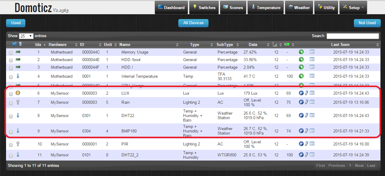
I got it to run on the breadboard, and sync with domoticz. and the plan is to power it out with some 18650 cells+solar panel, but i have some questions for you.
- aren't you using any resistors for the i2c sensors? or the dht22?
- how hare you connecting the battery? when fully charged it can go up to 4.2v i belive this whould burn some sensors.. are you connecting it to the arduino raw pin and feeding the sensors with the regulated 3.3v pin!?
- the potentiometer, are you using it only as a resistor? or are you regulating it?
thanks for sharing, and here are some screenshots of my implementation.
-
I don't seem to be able to get the DHT22 working. I have stripped this project down to the following prototype, and am still not able to get the DHT22 to work. I'm using the DHT example (not MySensors) script and continue to get timeout errors for both Temp and Humidity. I have tried a 4.0k ohm, 10k omh and no resistor.
I am just wanting to know if I might be missing something, and to also verify that other people have got the DHT22 working with a Arduino Pro Mini 8mhs - 3.3 volt using its regulated vcc pin. I have ordered new DHT22 modules from a different source just to see what happens.
Thanks in advance for any input.
-
One thing comes to mind is that DHT has 3.3v as minimum power.
If you have a "weak" pro mini board delivere power below that maybe is a problem. Can you measure the power?I have a 3.3v pro mini running a DHT22 fine, so it should work - but I also know there is a big difference in different hardware even if its called pro mini.
 or code(s)